For 1990-2009 cars only
Special Tools
| • | J 2619-O1 Slide Hammer With Adapter |
| • | J 29794 Extension |
| • | J 44394 Seal Protector |
| • | J-42943 Drive Axle Separator |
| • | J 45859 Wheel Hub Remover |
Removal Procedure
- Raise and support the vehicle. Refer to Lifting and Jacking the Vehicle .
- Remove the right front tire and wheel assembly. Refer to Tire and Wheel Removal and Installation .
- Remove the right front outer tie rod from the steering knuckle. Refer to Steering Linkage Outer Tie Rod Replacement .
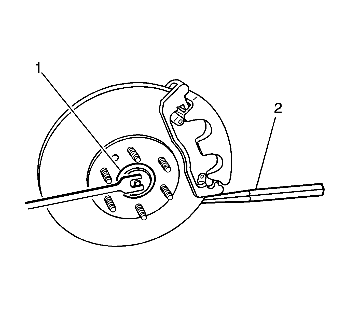
- Insert a drift or a punch (2) in the brake rotor against the brake caliper mounting bracket.
- Using a breaker bar and the proper size socket (1), loosen the wheel drive shaft nut.
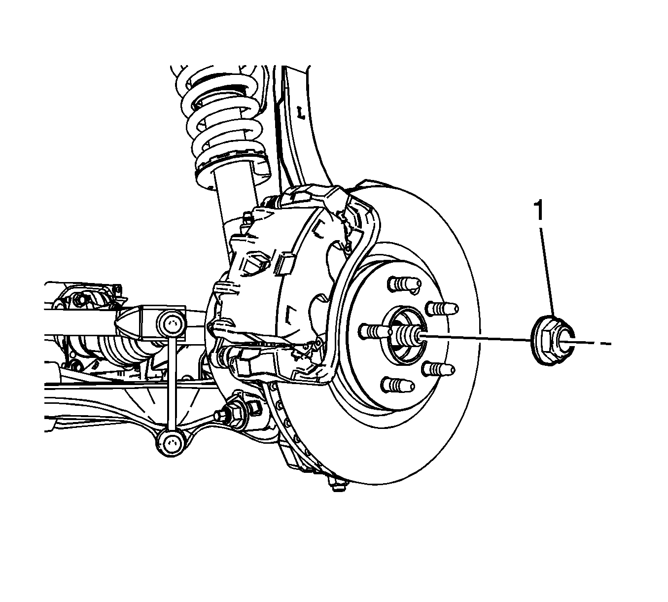
- Remove and discard the wheel drive shaft nut.
- Remove the right front wheel speed sensor. Refer to Front Wheel Speed Sensor Replacement .
- Remove the upper ball joint from the steering knuckle. Refer to Shock Absorber and Spring Assembly Replacement .
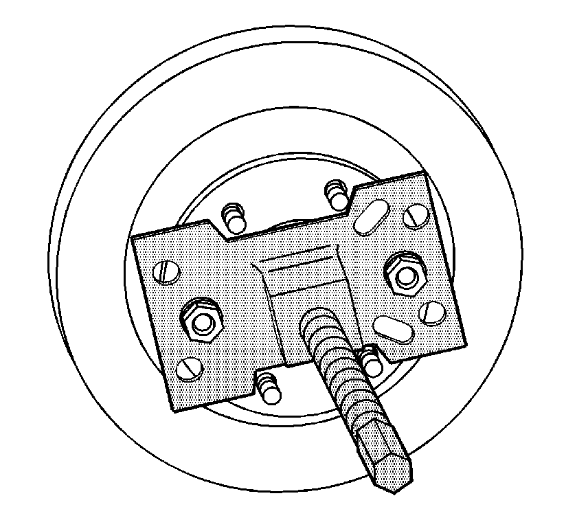
- Install the J 45859 on the brake rotor and secure with the wheel nuts.
- Using the J 45859 , remove the wheel drive shaft from the steering knuckle.
- Remove the J 45859 from the brake rotor.
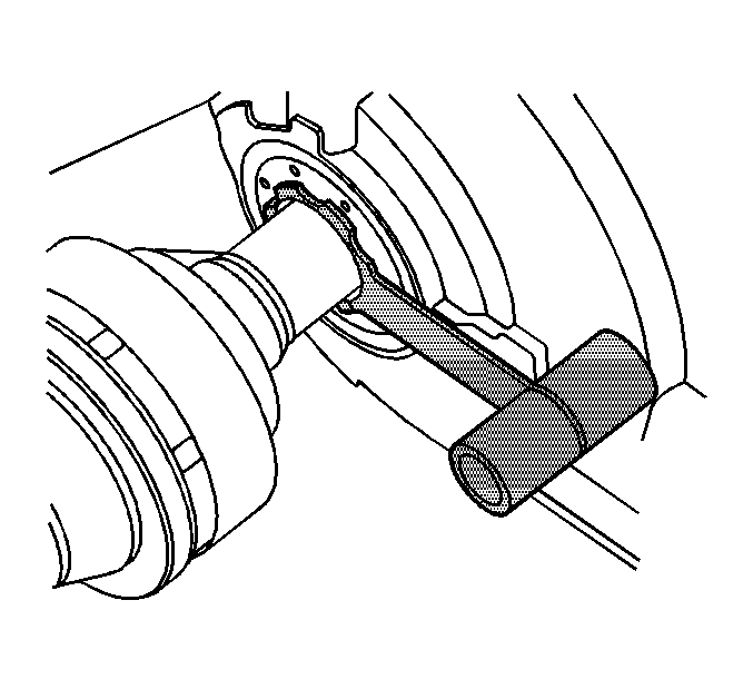
- Assemble the J 2619-O1 , the J 29794 , and the J-42943
- Install the J 2619-O1 , J 29794 , and the J-42943 to the inner tripod housing.
- Using the J 2619-O1 , J 29794 , and the J-42943 , remove the wheel drive shaft from the differential enough to install J 44394 .
- Carefully install the J 44394 over the wheel drive shaft.
- Carefully slide the J 44394 into the differential output shaft seal.
- Remove the wheel drive shaft and the J 44394 from the vehicle.


Important: DO NOT reuse the wheel drive shaft nut, replace with a NEW wheel drive shaft nut.


Notice: J-44394 must be installed into the differential output shaft seal prior to removing and installing the wheel drive shaft. Failure to install J-44394 as indicated may cause the splines of the wheel drive shaft to cut the differential output seal.
Important: If the wheel drive shaft seal is found to be damage, replace the seal.
Installation Procedure
- Install the J 44394 in the differential assembly.
- Install the wheel drive shaft until the splines are past the J 44394 .
- Remove the J 44394 from the wheel drive shaft and continue to install the drive shaft until it is fully seated.
- To ensure that the wheel driver shaft is installed properly, grasp the inner tripod housing and pull it outward. DO NOT pull on the axle shaft.
- Install the right front wheel drive shaft into the wheel hub/bearing assembly.
- Install the upper ball joint in the steering knuckle. Refer to Shock Absorber and Spring Assembly Replacement .
- Install the NEW wheel drive shaft nut.
- Insert a drift or punch (2) in the brake rotor and against the brake caliper mounting bracket in order to keep it from turning.
- Using a breaker bar and the proper size socket (1), tighten the wheel drive shaft nut until the wheel drive shaft is fully seated in the wheel hub/bearing assembly.
- Tighten the wheel drive shaft nut.
- Remove the drift or punch (2) from the brake rotor.
- Install the wheel speed sensor. Refer to Front Wheel Speed Sensor Replacement .
- Install the right outer tie rod end. Refer to Steering Linkage Outer Tie Rod Replacement .
- Install the right front tire and wheel assembly. Refer to Tire and Wheel Removal and Installation .
- Remove the support and lower the vehicle.


Notice: Refer to Fastener Notice in the Preface section.
Tighten
Tighten the wheel drive shaft nut to 215 N·m (158 lb ft).
