Special Tools
J 24319-B Steering Linkage and Tie Rod Puller
Removal Procedure
- Raise and support the vehicle. Refer to Lifting and Jacking the Vehicle.
- Remove the tire and wheel. Refer to Tire and Wheel Removal and Installation.
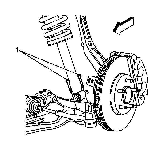
- Remove the lower mounting bolts for the shock absorber.
- Remove the front shock yoke. Refer to Front Shock Absorber Yoke Replacement.
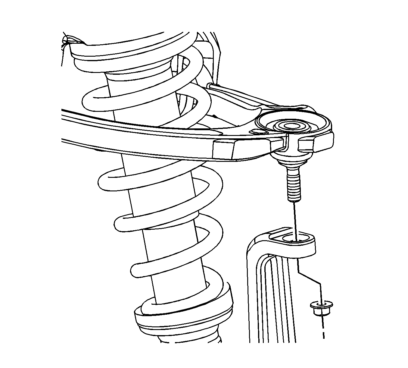
- Remove the upper control arm to steering knuckle nut.
- Using the J 24319-B , remove the upper control arm from the steering knuckle.
- Lower the vehicle.
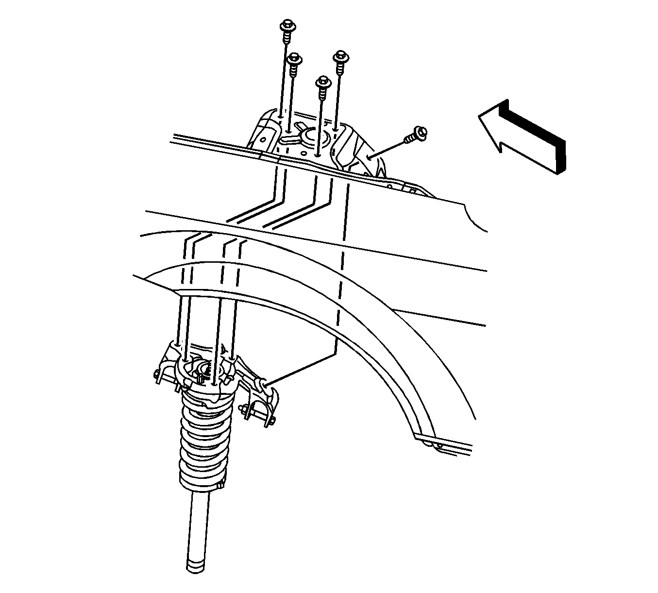
- Remove the front shock absorber assembly upper mounting bolts.
- Remove the front shock absorber assembly from the vehicle.
- If servicing the front spring, or related parts, refer to Shock, Shock Component, and/or Spring Replacement.

Important: Step 3 is for rear wheel drive (RWD) vehicles drive only.
Important: Step 4 is for vehicles equipped with all wheel drive (AWD) only.

Notice: The ball stud must not rotate during disassembly or reassembly. Hand tools must be used to keep the ball stud from rotating. If air tools are used and the stud is allowed to rotate, damage to the ball stud and/or stud mounting hole may occur.
Important: Hold the upper control arm to the steering knuckle when removing the retaining nut.
Important: To prevent the ball stud from slipping, insert a hex-head tool while removing the upper control arm-to-steering knuckle nut.

Installation Procedure
- Install the front shock absorber assembly in the vehicle.
- Install the front shock assembly upper mounting bolts.
- Raise the vehicle.
- Install the upper control arm to the steering knuckle.
- Install the upper control arm to steering knuckle retaining nut.
- Install the lower mounting bolts for the shock absorber.
- Install the shock to the shock absorber yoke. Refer to Front Shock Absorber Yoke Replacement.
- Install the tire and wheel. Refer to Tire and Wheel Removal and Installation.
- Lower the vehicle.

Notice: Refer to Fastener Notice in the Preface section.
Tighten
Tighten the bolts to 112 N·m (83 lb ft).

Tighten
Tighten the nut to 80 N·m (59 lb ft).

Important: Step 6 is for RWD vehicles only.
Tighten
Tighten the nut to 25 N·m (18 lb ft).
Important: Step 7 is for AWD vehicles only.
