Service Manual Procedures for New Lock System for Interim 1997 Saturns

| Subject: | Service Manual Procedures for New Lock System for Interim 1997 Saturn |
| Models: | 1997 Saturns |
Purpose
Saturn interim 1997 vehicles will be manufactured with a new lock system for the ignition, door and rear compartment/liftgate locks. (This new lock system will be referred to as second design and the previous lock system will be identified as first design.) To help identify if a vehicle is equipped with a first or second design lock system, check the key. The new second design lock system has a different shaped key then the key used in the first design lock system (refer to the following illustrations).
Refer to this bulletin for new general information and coding procedures for the new second design lock system.

First Design Key

Second Design Key
General Information

Key Identification and Usage
The second design lock system is a one key system with a key profile that has a two-sided cut, and milled grooves that are unique to the Saturn lock system. The number of tumblers in the ignition cylinder has increased form seven to nine.
Cutting Keys
The Saturn approved key cutting tool requires adapter kit SA9703B to cut the second design keys. The adapter kit consists of a depth knob, spacing plate, key insert, and punch and die assembly. To install adapter kit to key cutting tool, follow steps in instruction manual provided with key cutting tool. The spacing plate provided with the adapter kit accommodates positions 1 through 10. The Saturn key uses position 2 through 10.
Important: First design keys cannot be cut with the adapter kit.
The customer information card or the retailer records will show the key code as a four-digit numeric code. To determine the actual cut sequence of the key from this code, look up the code in the 1991-1997 Saturn Key Code Manual and the cur sequence will be shown to the right of the code listing. The master cut sequence should be used to cut new keys, as it has all of the cuts necessary for the key to work properly in all the locks on the vehicle.
Determining the Key Code
- Insert the key in the Saturn approved key cutting tool with the tip of the key against the stop.
- With the cutting die in the down position, move the carriage toward the die until it bottoms out, and record the depth (1, 2, 3 or 4).
- Repeat for each cut position, 2 through 10. Positions are read from key head to key tip.
Procedures
Lock Cylinder Coding
- Push tumblers out of lock cylinder using a thin-bladded screwdriver.
- For door and rear compartment or liftgate locks, if necessary, remove side-bar assembly by pushing it inward while tapping the cylinder, causing it to fall out.
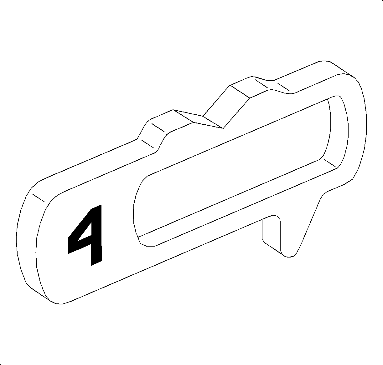
- Select the correct tumblers for the desired code by the number stamped on the tumbler. (Illustration shows a number 4 tumbler.)
- Install tumblers by applying downward pressure until they lock into position.
- To check coding of the cylinder, insert key. If coding is correct, tumblers and side-bar will be flush with cylinder with key inserted.
- For assembly, oil lock set with a light oil or graphite lubricant.

Important: When the tumblers are removed from the lock cylinder, tumbler springs may fall out.
| • | Door, rear compartment and liftgate lock cylinders reads key cut positions 5 through 10. |
| • | Ignition lock cylinder reads key cut positions 2 through 10. |

Important: Make sure side-bar (if used) and tumbler springs are in place before installing tumblers.
Door Lock Cylinder
Removal
- Remove cap from lock cylinder using a thin-bladed screwdriver to carefully pry cap from cylinder.
- Remove shutter and shutter springs.
- Insert key into cylinder, turn it a quarter turn clockwise, and remove cylinder from housing.
- If necessary, remove pawl from slot in housing.
- To code lock cylinder(s), refer to Lock Cylinder Coding in this bulletin.

Important: When shutter is removed, the shutter spring may fall out.

Installation
- If removed, insert pawl into slot in housing.
- With key inserted into cylinder, install cylinder into housing.
- Remove key by turning it a quarter turn counter clockwise.
- Install shutter springs and shutter assembly.
- Install cap onto lock cylinder.

Ignition Lock Cylinder
Removal
- Remove shroud fasteners (5.5 mm hex head) and remove steering column upper shroud panel.
- Insert key into ignition lock cylinder and rotate to ACC position.
- Depress the square locking button on the top of ignition module assembly and slide lock cylinder assembly from ignition module housing.
- Remove key from lock cylinder.
- Remove lock cylinder bezel by carefully prying from lock cylinder housing with thin-bladed screwdriver.
- Insert key into ignition lock cylinder assembly and depress lock pin at rear of lock cylinder using a thin-bladed screwdriver.
- Rotate cylinder and remove locking pin.
- Remove cylinder from case.
- To code lock cylinder, refer to Lock Cylinder Coding in this bulletin.
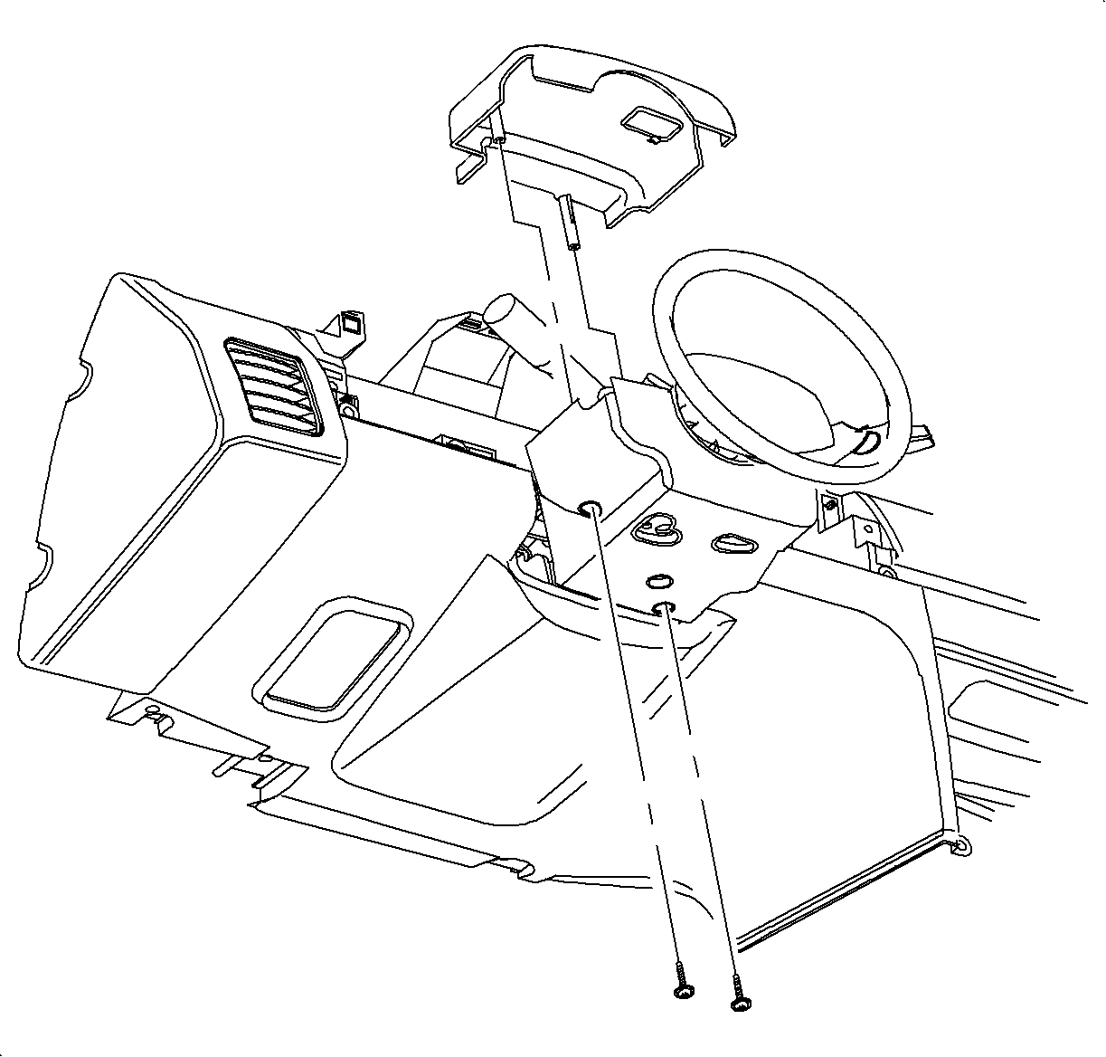
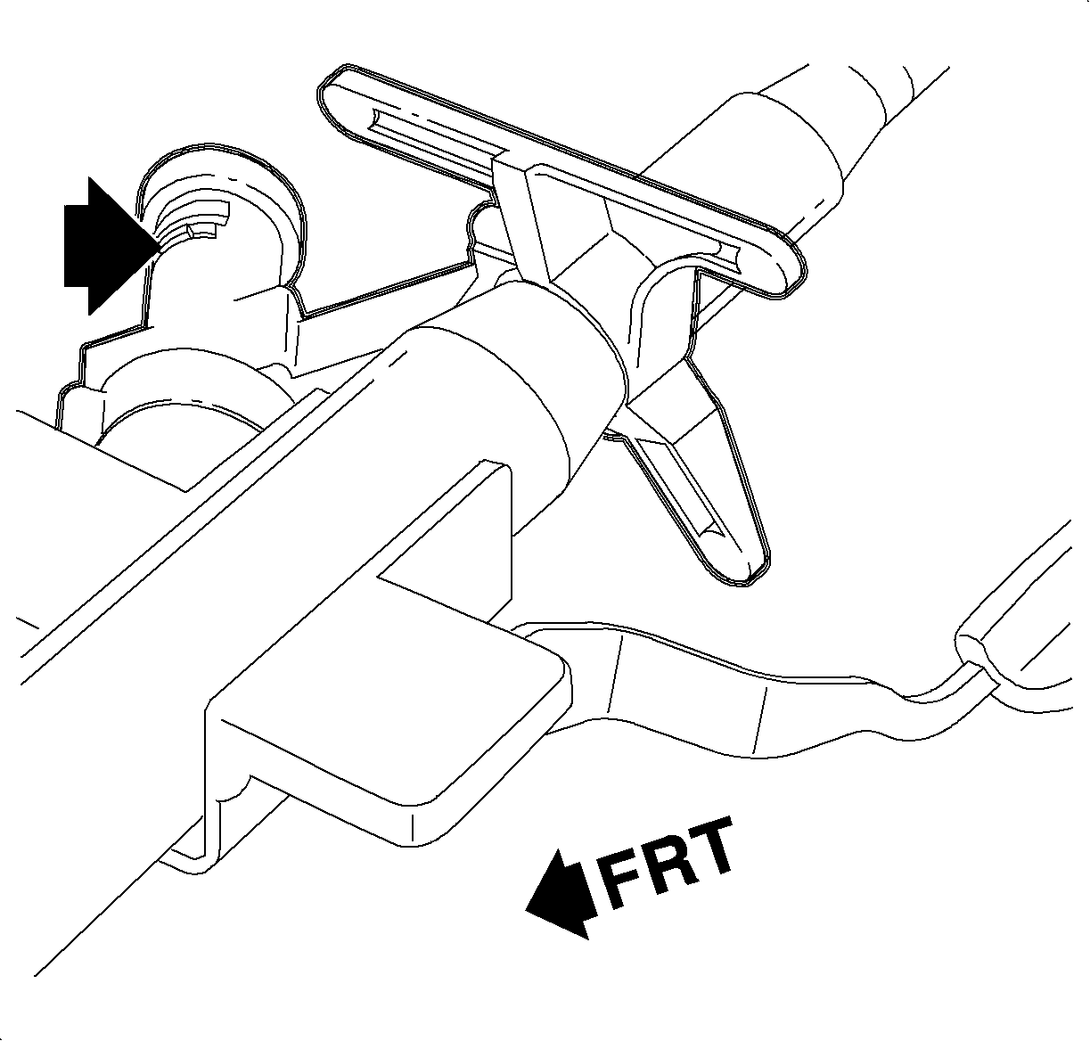
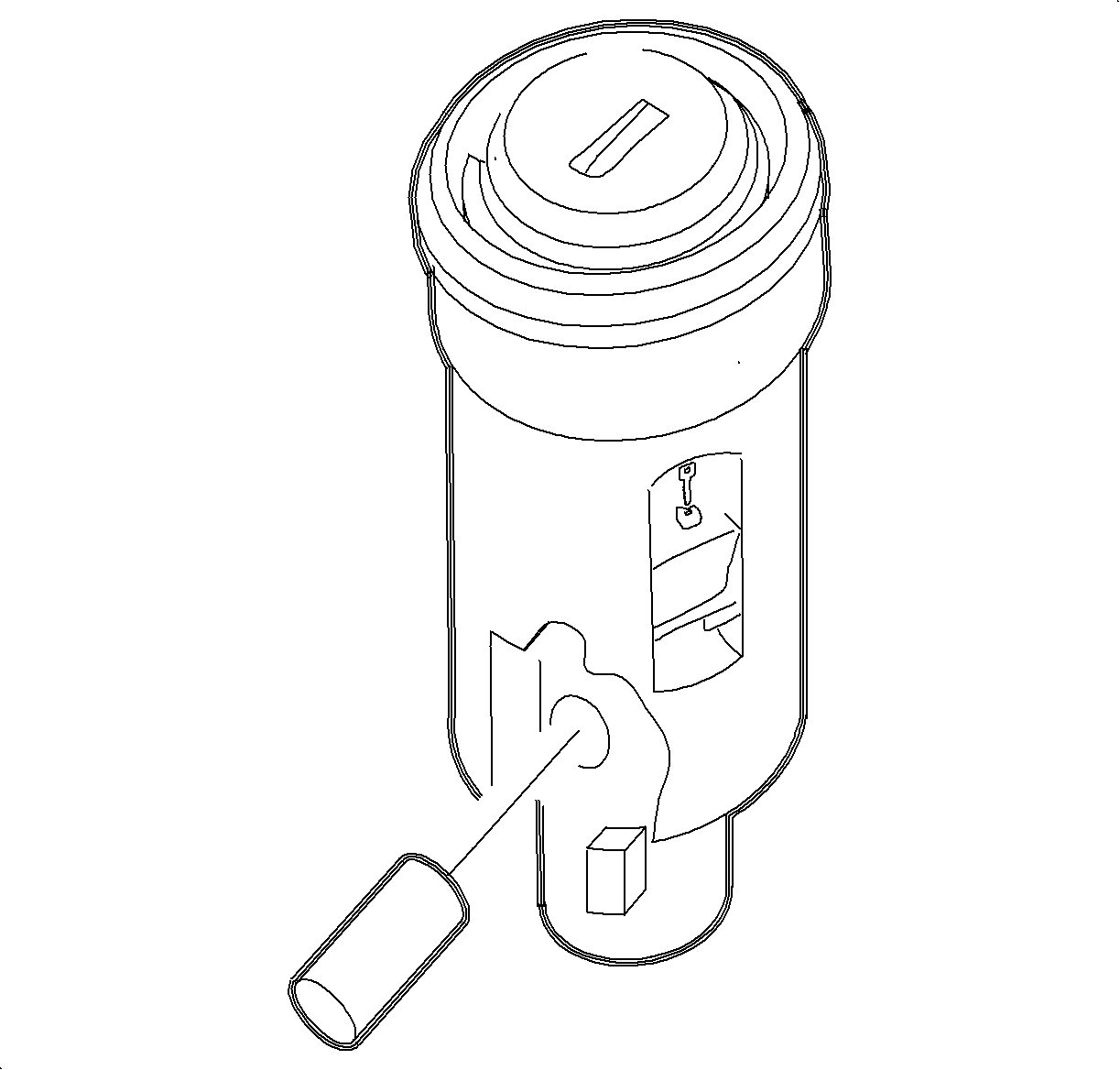
Notice: Lock pin is under pressure, be careful not to lose lock pin when removing from lock cylinder.

Installation
- With key inserted into cylinder, install cylinder into case.
- Rotate cylinder and install spring and locking pin.
- Install lock cylinder bezel to lock cylinder housing.
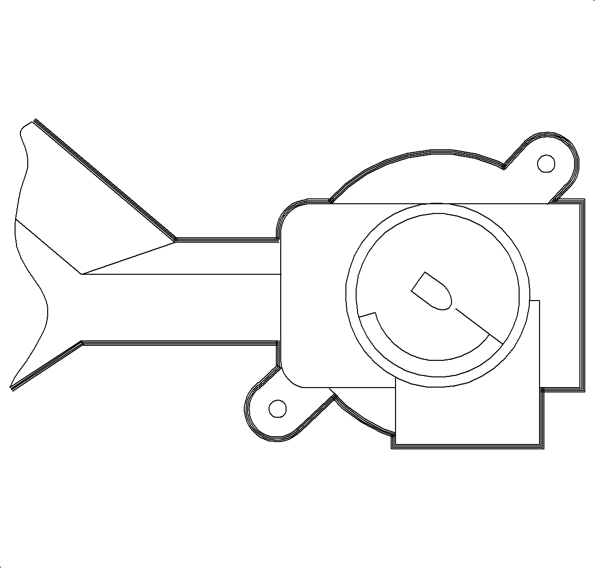
- Important: Actuator blade within ignition module housing must be in the ACC position to install lock cylinder assembly. If rotated, replace it to the ACC position using needle nose pliers.
- With lock cylinder in ACC position, slide lock cylinder assembly into ignition module.
- Install steering column upper shroud panel and shroud fasteners.



Tighten
Tighten the shroud fasteners to 3 N·m (26 lb in).
Rear Compartment and Liftgate Lock Cylinder
Removal
- Remove E-clip at rear of lock cylinder and remove pawl.
- Unhook return spring from case and slide spring from cylinder.
- Remove cap from lock cylinder by inserting thin-bladed screwdriver between cap and case, and carefully prying cap from case.
- Remove shutter.
- Insert key and rotate a quarter-turn clockwise, and slide cylinder from housing.
- To code lock cylinder, refer to Lock Cylinder Coding in this bulletin.


Important: When shutter is removed, the shutter springs may fall out.

Installation
- With key inserted into cylinder, install cylinder into housing.
- Install shutter spring and shutter assembly.
- Install cap to lock cylinder housing.
- Slide spring on to cylinder and hook to case.
- Install pawl to lock cylinder and secure with E-clip.


Parts Requirements
P/N | Part Description | Usage |
|---|---|---|
21170409 | Package - Frt S/D Lk Cyl | All |
21170390 | Package - R/Compt Lid Lk Cyl | A69/27 |
21170414 | Package - Ign Lk Cyl | All |
21170408 | Package - L/Gate Lk Cyl | A35 |
21170632 | Package - Frt S/D Lk Cyl | RHD |
21170338 | Lock Service Kit Complete | All |
Lock Service Kit Complete Contains the Following Parts | ||
21170389 | Box - Lk Service Kit | N/A |
21170413 | Pawl - Frt S/D Lk Cyl, L | All |
21170412 | Pawl - Frt S/D Lk Cyl, R | All |
21170406 | Pawl - R/Cmpt Lid Lk Cyl | A69/27 |
21170407 | Pawl - L/Gate Lk Cyl | A35 |
21170411 | Spring - Ign Lk Pin | All |
21170415 | Pin - Ign Lk Cyl | All |
21095084 | Switch Asm - Frt S/D Lck | RHD |
21044505 | Bezel - Ign & Start Sw | All |
21170392 | Tumbler - Lk Cyl #1 | All |
21170393 | Tumbler - Lk Cyl #2 | All |
21170394 | Tumbler - Lk Cyl #3 | All |
21170395 | Tumbler - Lk Cyl #4 | All |
21170396 | Shutter - Dr & R/Cmpt Lk Cyl Cap | All |
21170397 | Spring - Dr & R/Cmpt Lk Cyl Shtr | All |
21170398 | Spring - Dr, R/Cmpt & Ign Lk Cyl Tumb | All |
21170339 | Clip - R/Compt Lid Lk Cyl | All |
21170400 | Retainer - R/Cmpt Lid Lk Cyl | A69/27 |
21170401 | Gasket - R/Cmpt Lid Lk Cyl | A69/27 |
21170402 | Gasket - L/Gate Lk Cyl | A35 |
21170403 | Spring - R/Cmpt Lid Lk | A69/27 |
21170577 | Spring - L/Gate Lk Cyl Ret | A35 |
21170404 | Cap - Frt S/D Lock Cyl | All |
21077412 | Cap - L/Gate Lk Cyl | A35 |
21097822 | Boot - R/Cmpt Lid Lk Cyl | A69/27 |
21170452 | Side Bar - Dr Lk Cyl | All |
21170453 | Spring - Side Bar | All |
21170391 | Key - Dr & R/Compt & Ign | All |
