Special Tools
Removal Procedure
- Remove the intake manifold. Refer to
Intake Manifold Replacement
.
- Remove the exhaust manifold. Refer to
Exhaust Manifold Replacement
.
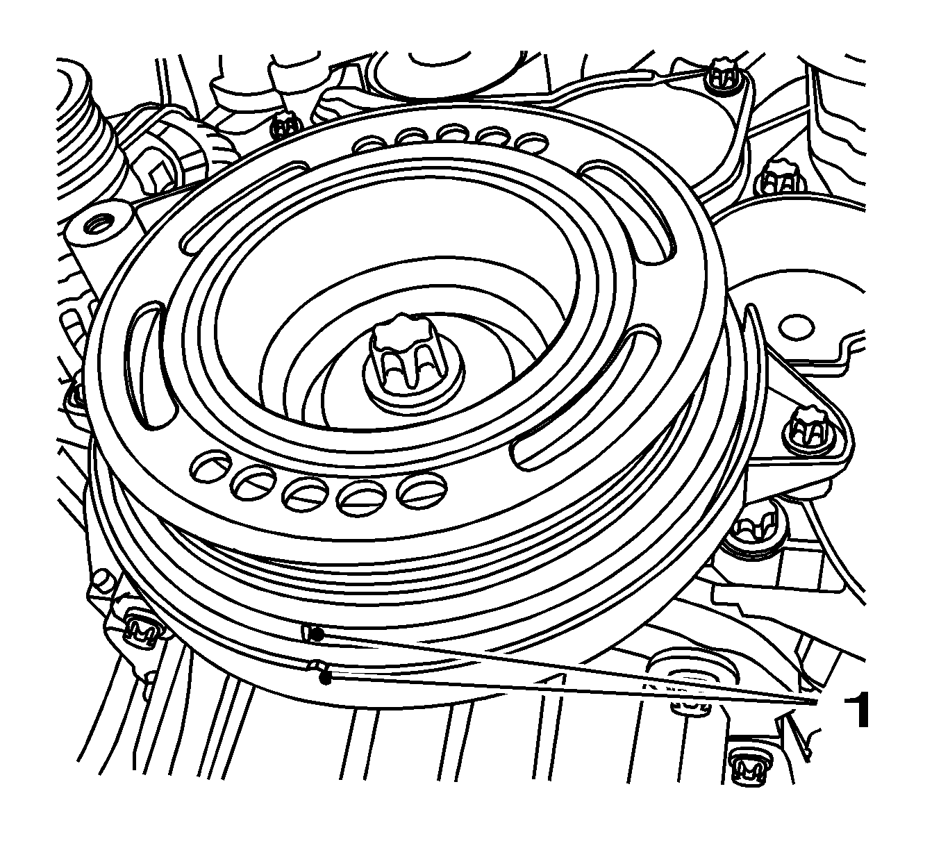
- Set the engine to "TDC".
Set the torsional vibration balancer in the direction of engine rotation to "1st cylinder TDC" (mark 1).
- Remove the front toothed belt cover (lower). Refer to
Timing Belt Lower Front Cover Replacement
.
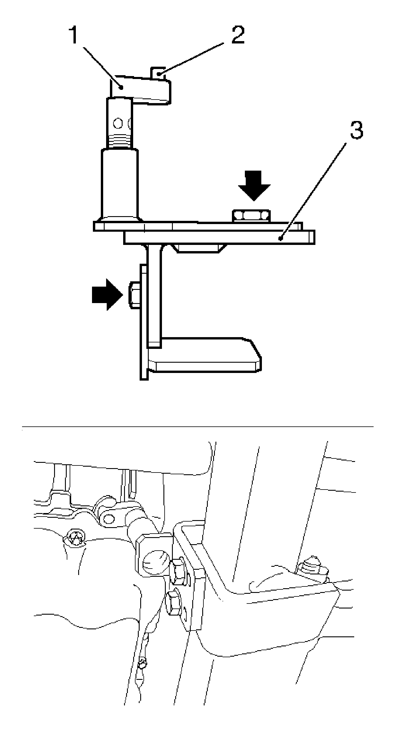
- Insert KM-6173 Adapter (3).
| • | Loosen the 4 bolts (arrows) and hand-tighten. |
| • | Align KM-6173 at frame. |
| • | Position the support bearing (1). |
| • | Journal (2) must sit in the mount at the cylinder block. |

Important: Attaching
KM-6001-A
guarantees perfect alignment of the drive unit with the frame.
- Attach
KM-6001-A
(1).
| • | Loosen the 3 bolts (arrows) in the adjusting rails. |
| • | The journals (2, 5) must sit in the guide holes of the frame. |
| • | Tighten the 3 bolts in the adjusting rails. |
| • | Adjust the support bearings, front (4) and rear (3). |
| | Important: The guide journals must be seated free from play in the support bearings.
|
| • | Raise the support bearings up to the stop on the guide journals. |
- Lower the vehicle by its full height.
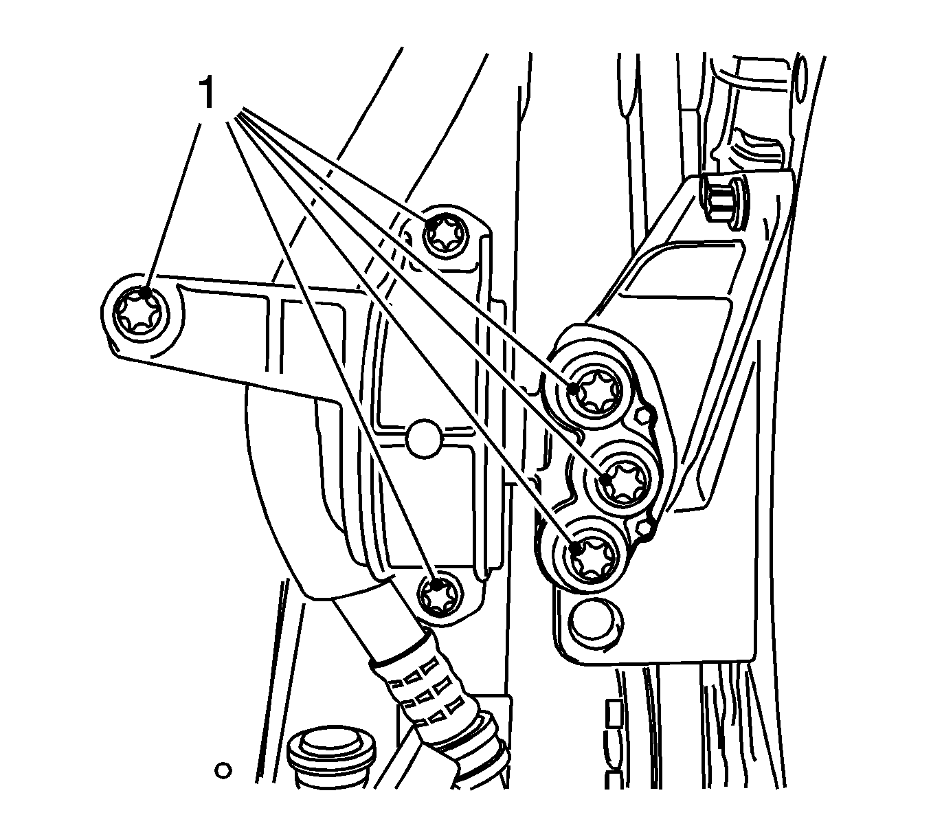
- Remove the engine damping block, right hand side.
Remove the 6 bolts (1).
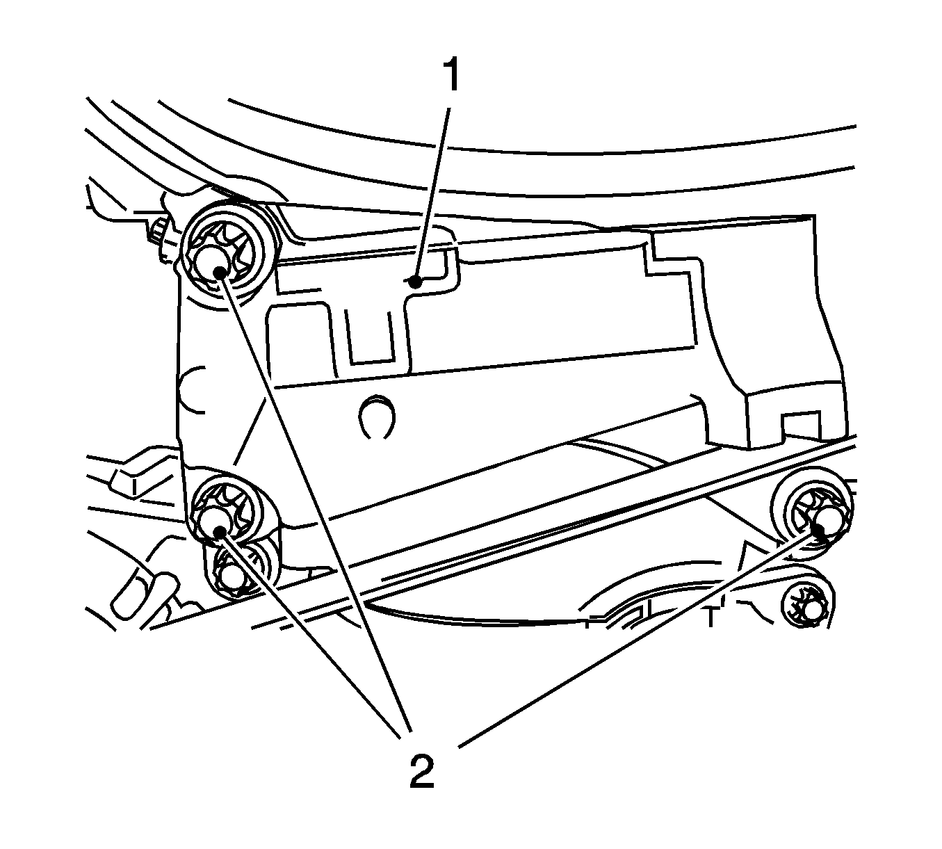
- Remove the engine damping block support (1).
Remove the 3 bolts (2).
- Remove the front toothed belt cover (top). Refer to
Timing Belt Upper Front Cover Replacement
.
- Remove the front toothed belt cover (center). Refer to
Timing Belt Center Front Cover Replacement
.
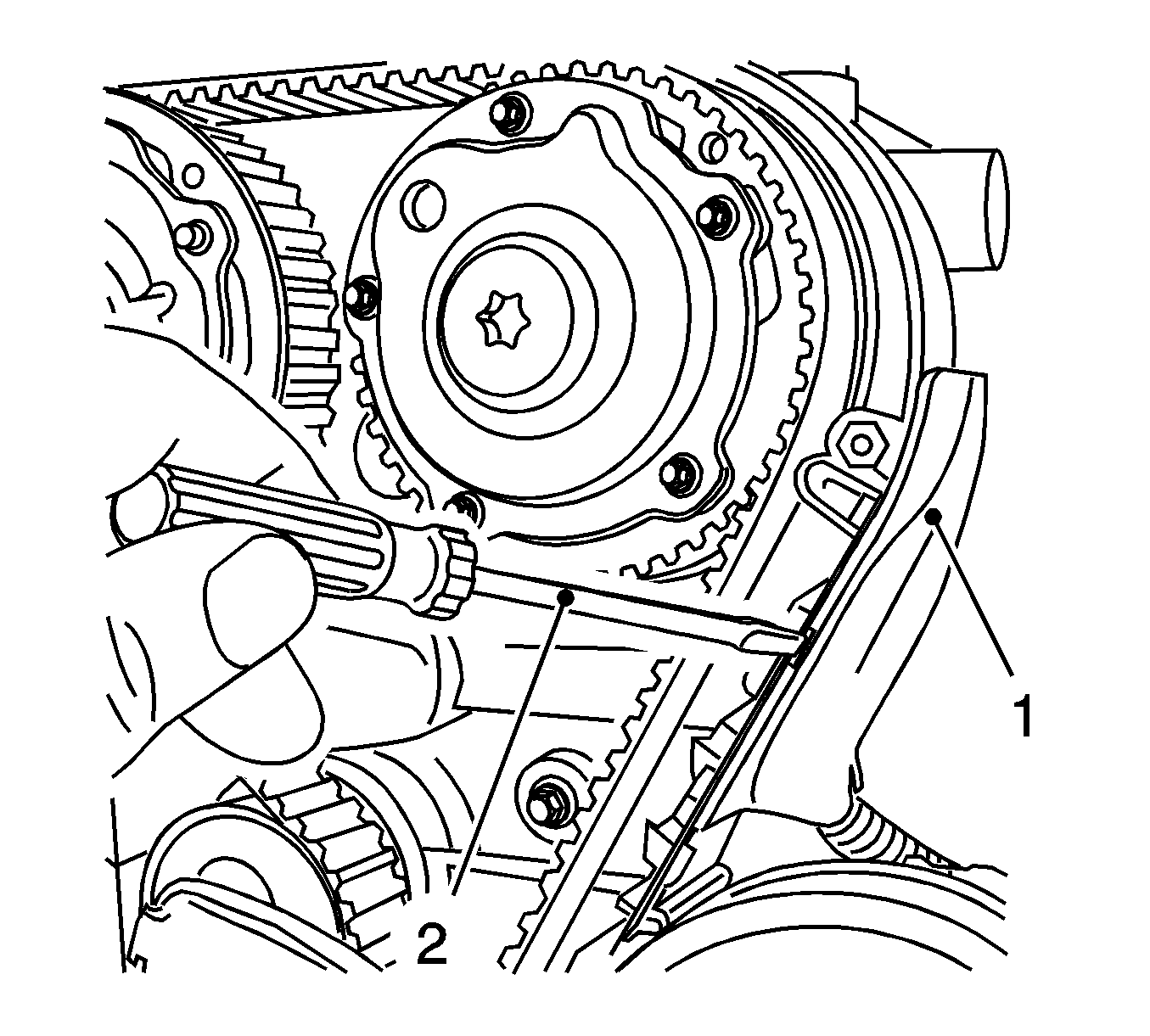
- Disconnect the wiring trough cover (1) from the rear toothed belt cover.
Release with a screwdriver (2).

Important: Recognizable from the lettering "Right" (arrow)
- Prepare the right half of
MK-6340
for use on the U 18 XER engine.
| • | Detach the front panel (1) from
MK-6340
. |
| • | Remove the 2 bolts (2). |
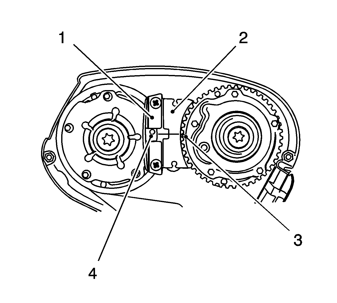
- Insert
MK-6340
into the camshaft timing gears.
| • | Insert
MK-6340
(1, 2) in the camshaft adjuster as shown. |
| | Important: The spot-type marking (4) on the intake camshaft adjuster does not correspond to the groove of
MK-6340
during this process but must be somewhat above as shown.
|
| • | The spot type marking (3) on the exhaust camshaft adjuster must correspond to the groove on
MK-6340
. |
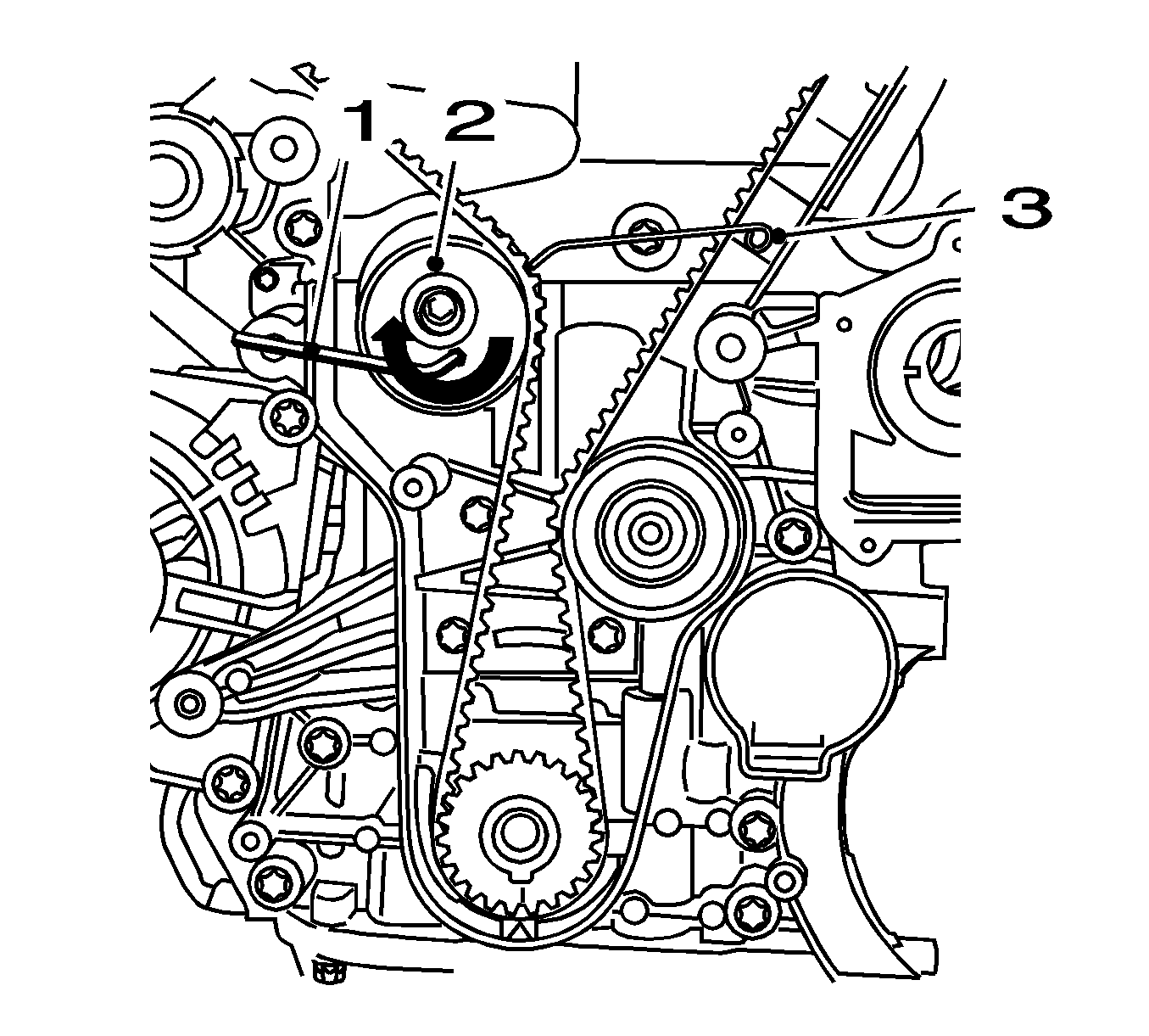
- Block the toothed belt tensioner.
Apply tension to the toothed belt tensioner (2) in the direction of the arrow, using an Allen key (1). Fix using
KM-6333
(3).
- Mark the toothed belt direction of rotation.
- Remove the toothed belt.
- Remove the toothed belt guide roller.
Remove the bolt.
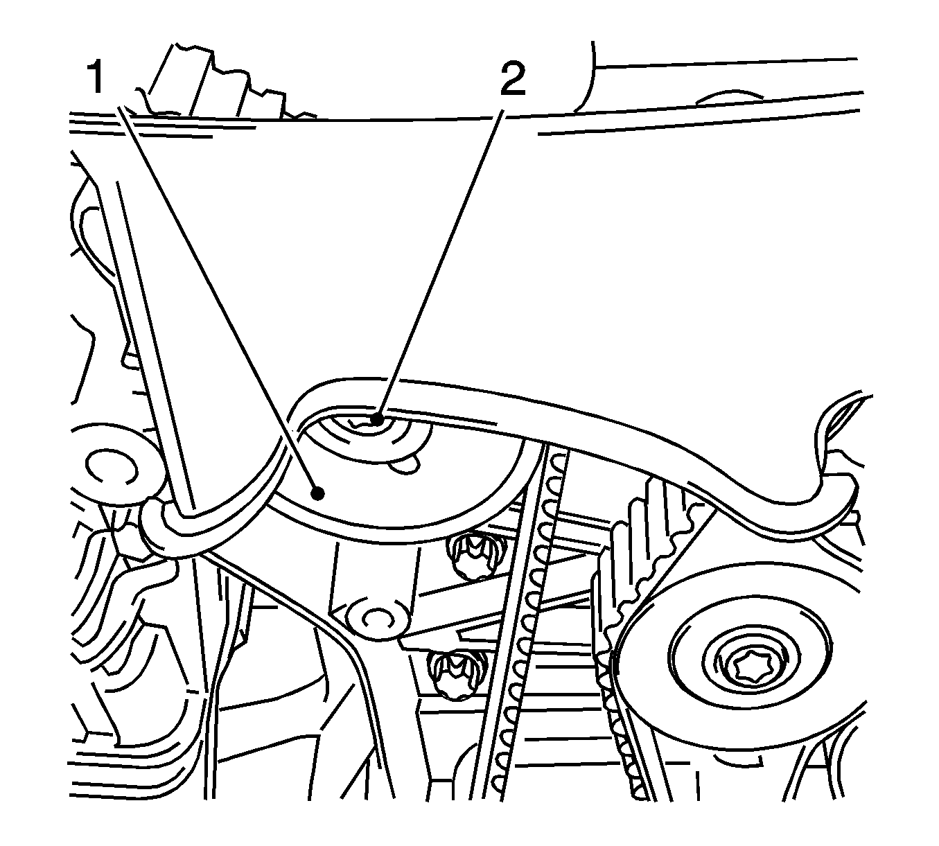
- Remove the toothed belt tensioner (1).
Remove the bolt (2)
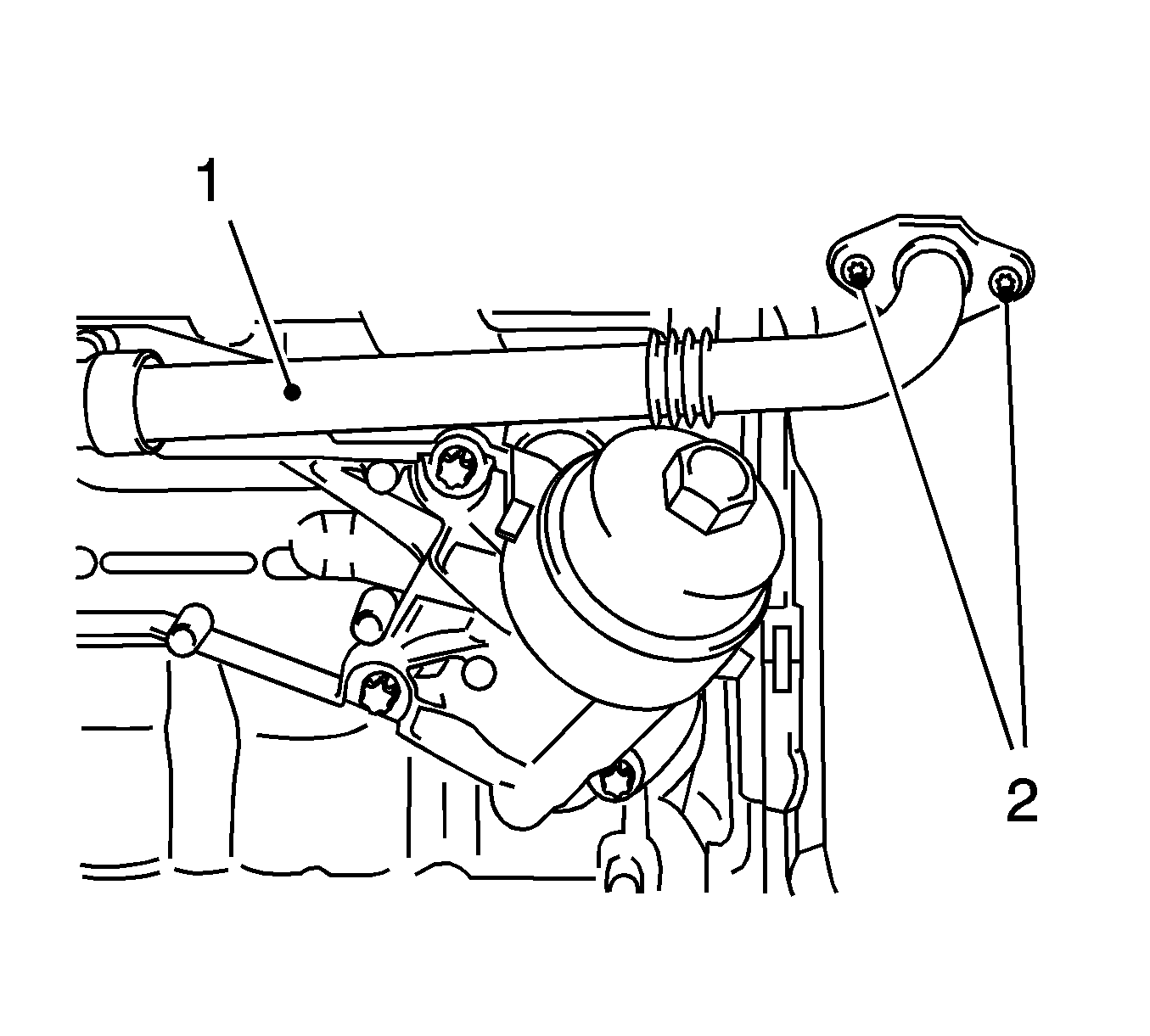
- Remove the coolant pipe (1) between the thermostat housing and the oil filter housing adapter.
| • | Remove the 2 bolts (2). |
| • | Remove the oil filter housing adapter. |
- Detach the 3 coolant hoses from coolant flange.
Remove the 3 clamps.
Important: Remove the cylinder head only when the engine is cold (room temperature).
- Remove the cylinder head cover. Refer to
Camshaft Cover Replacement
.
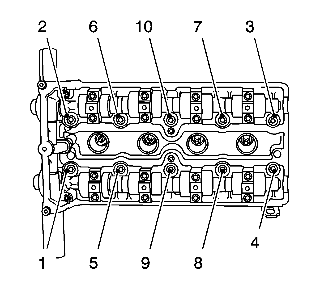
- Remove the cylinder head.
Important: Unfasten bolts in the order shown.
- Remove the 10 bolts.
| 23.1. | Undo the 10 bolts (90 degrees). |
| 23.2. | Undo the 10 bolts (180 degrees). |
- Remove the cylinder head.
| • | Place the cylinder head on suitable base. |
| • | Remove cylinder head gasket. |
Installation Procedure
- Clean the sealing surfaces.
- Inspect for plane surface.
| • | Cylinder block, cylinder head |
| • | Straight-edge, feeler gauge |
- Position the cylinder head.
| • | Install the cylinder head gasket. |
| • | Position the cylinder head. |
Notice: Refer to Fastener Notice in the Preface section.
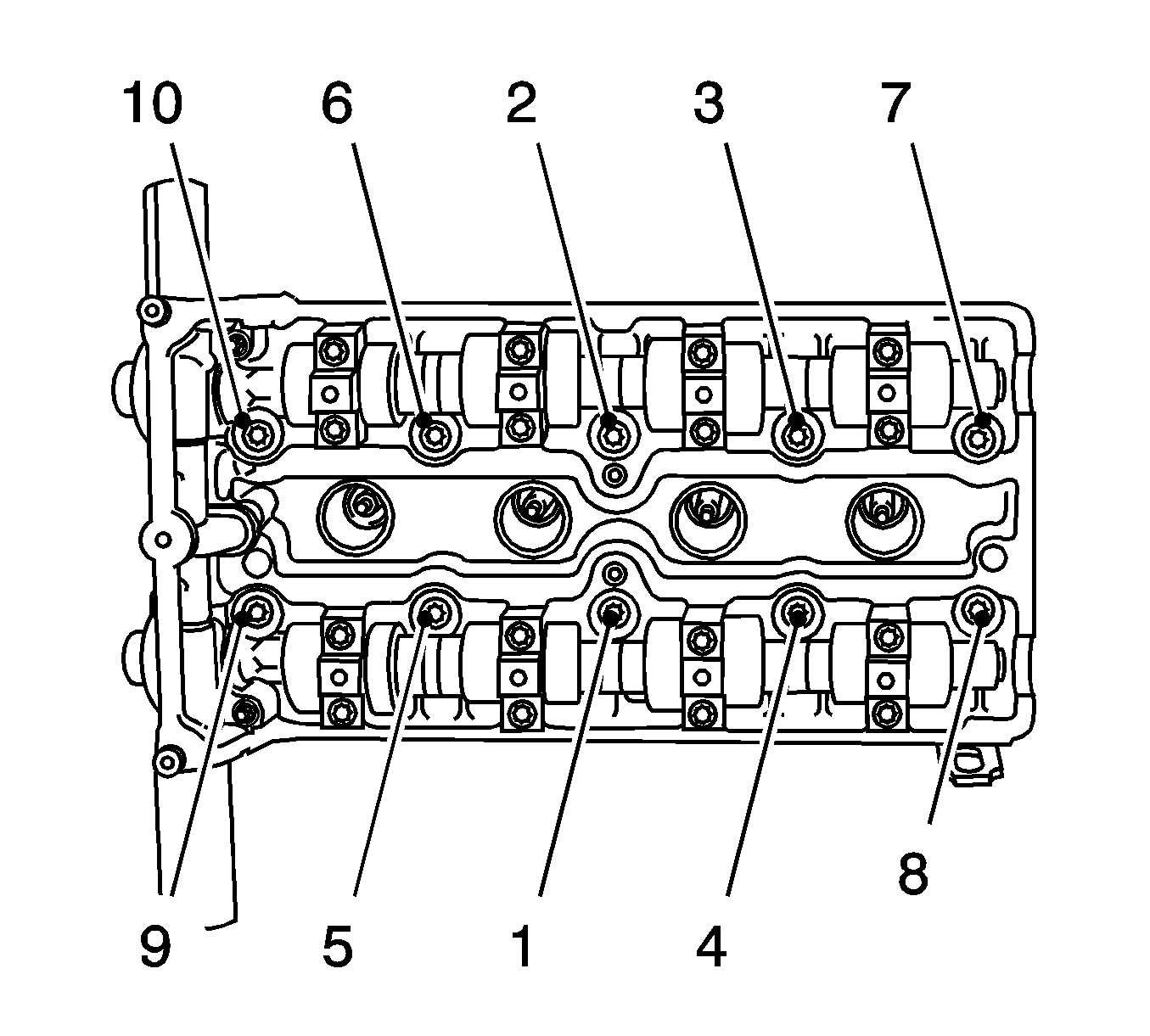
- Install the cylinder head.
Important: Note correct tightening sequence.
- Use new cylinder head bolts.
Tighten
Tighten the 10 bolts to 25 N·m (18 lb ft) plus 90 degrees plus 90 degrees plus 90 degrees plus 45 degrees.
- Attach the 3 coolant hoses to the coolant flange.
Attach the 3 clamps.
- Install the thermostat housing coolant pipe to the oil filter housing adapter.
| • | Push into the oil filter housing adapter. |
Tighten
Tighten the 2 bolts to 9 N·m (80 lb in).
- Install the cylinder head cover. Refer to
Camshaft Cover Replacement
.
- Clean the thread.
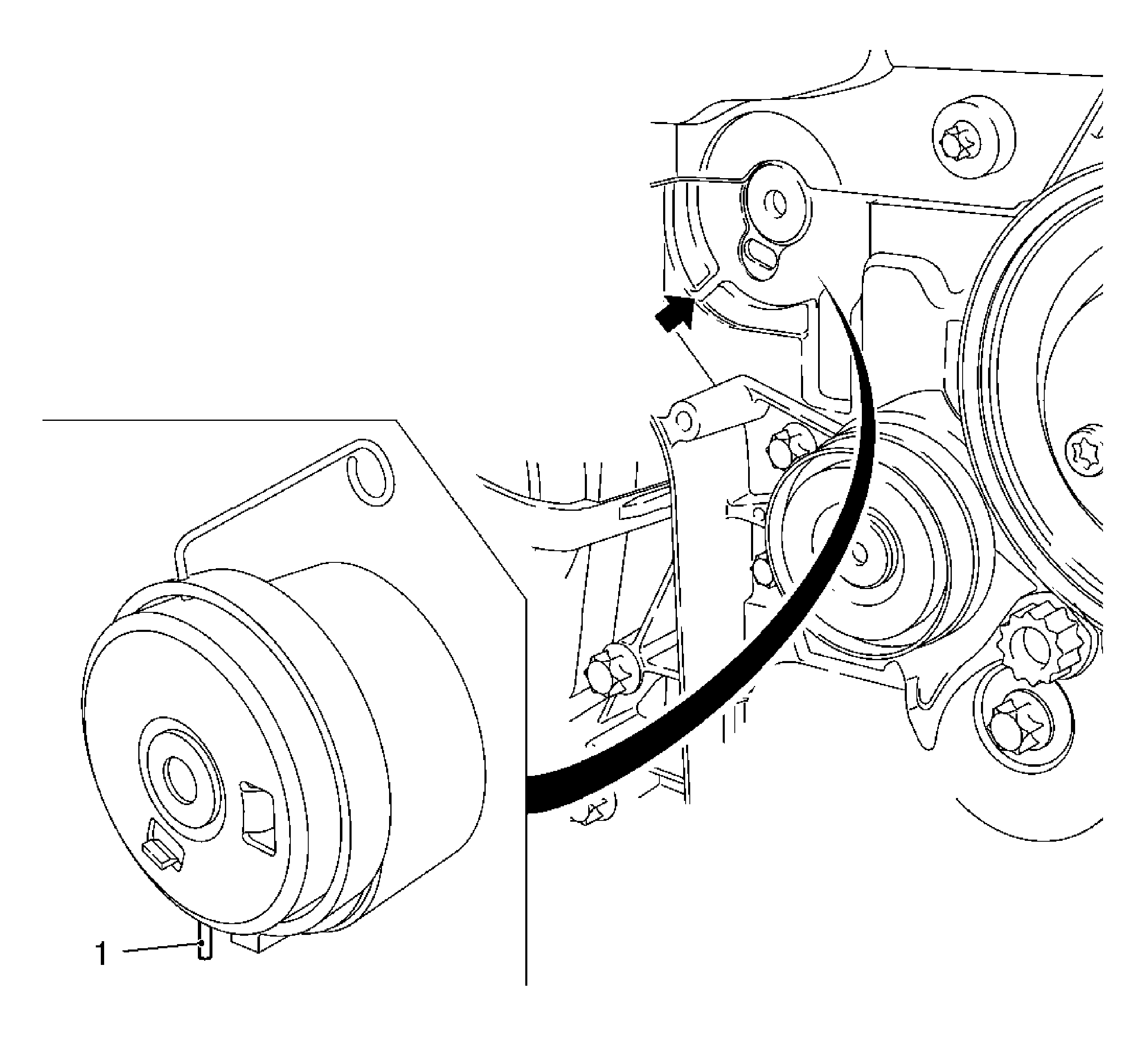
- Intake toothed belt tensioner.
Insert the toothed belt tension roller.
Tighten
Tighten the bolt to 20 N·m (15 lb ft).
| • | Released leg of spring (1) of the toothed belt tension roller must engage in the cut-out (arrow) of the pump module. |
- Install the toothed belt guide roller.
Tighten
Tighten the new bolt to 25 N·m (18 lb ft).
- Insert the toothed belt.
- Release tension on the toothed belt tensioner.
| • | Apply preliminary tension clockwise to the toothed belt tension roller. |
- Connect the wiring trough cover to the rear toothed belt cover.
- Install the front toothed belt cover (center). Refer to
Timing Belt Center Front Cover Replacement
.
- Install the support for the engine damping block.
Tighten
Tighten the 3 bolts to 50 N·m (37 lb ft).
- Install the engine damping block.
Tighten
Tighten the 3 bolts to 55 N·m (40 lb ft).
| • | Attach to the side member. |
Tighten
Tighten the 3 bolts to 35 N·m (25 lb ft).
- Raise the vehicle by its full height.
- Remove KM-6173.
Remove the 4 bolts.
- Remove
KM-6001-A
.
Loosen the 3 screwed connections.
- Install the front toothed belt cover (lower). Refer to
Timing Belt Lower Front Cover Replacement
.
- Lower the vehicle by its full height.
- Inspect the position of the camshaft sprockets.
| | Important: Note marking, camshaft sprockets.
|
| • | Turn the crankshaft 720 degrees in the direction of engine rotation by the bolt on the torsional vibration damper. |
| • | Insert
MK-6340
into the camshaft timing gears. |
- Raise the vehicle by its full height.

- Inspect the crankshaft position.
Markings on the torsional vibration damper and the lower part of the toothed belt cover (arrows) must align.
- Lower the vehicle by its full height.
- Install the exhaust manifold. Refer to
Exhaust Manifold Replacement
.
- Install the intake manifold. Refer to
Intake Manifold Replacement
.
- Inspect and correct the engine oil level.
- Connect the battery.
Attach the negative connection to the ground terminal.
Tighten
Tighten the nut.
- Fill and bleed the cooling system. Refer to
Cooling System Draining and Filling
.
- For programming procedures, refer to
Control Module References
.
- Close the hood.


