Special Tools
Removal Procedure
- Open the hood.
Caution: Refer to Battery Disconnect Caution in the Preface section.
- Disconnect the battery.
- Raise the vehicle by its full height.

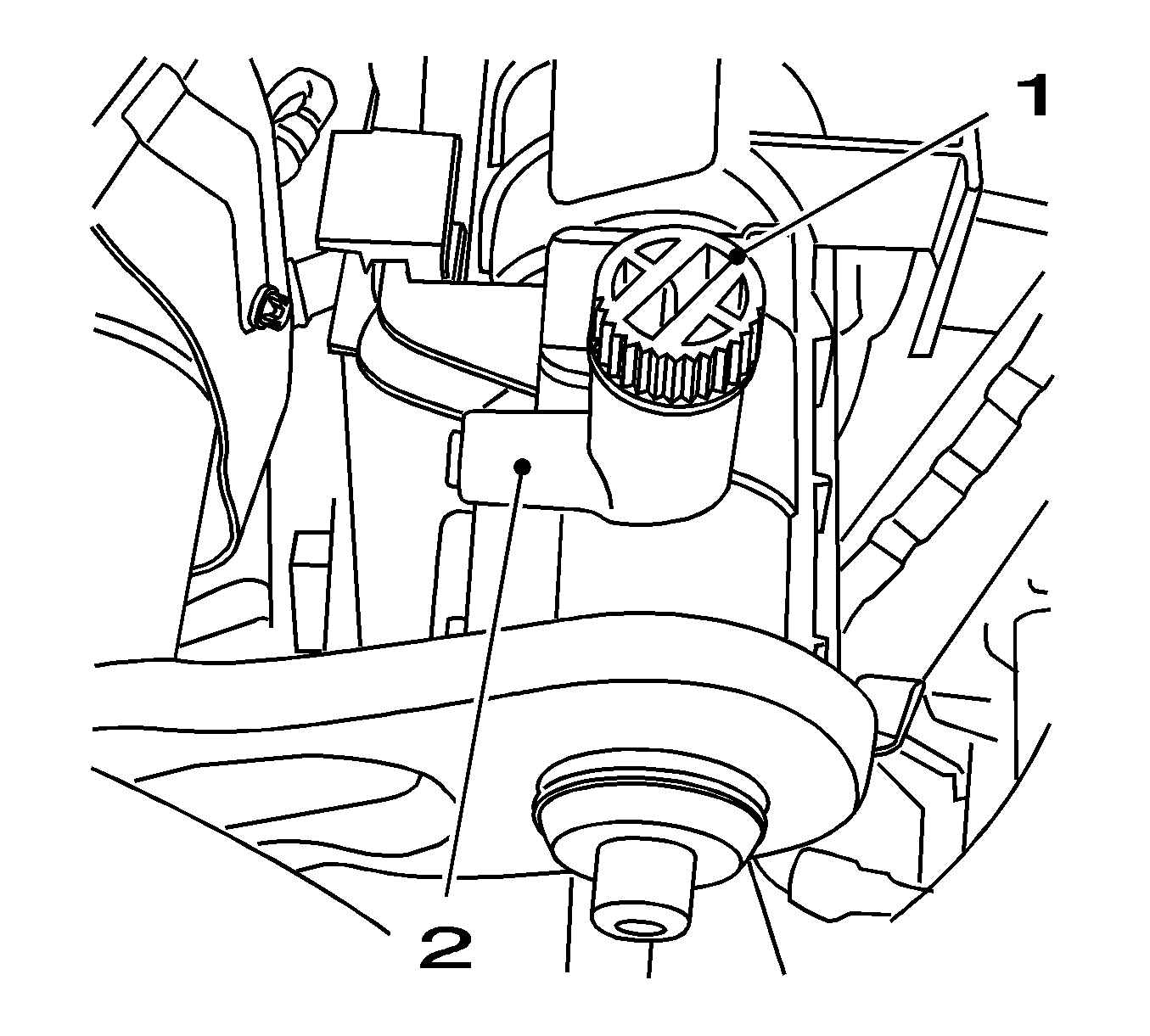
- Drain the coolant.
| • | Place a drip pan underneath. |
| • | Connect a suitable hose to the drain connection (2). |
| • | Open the coolant drain screw (1). |
| • | Close coolant drain screw. |

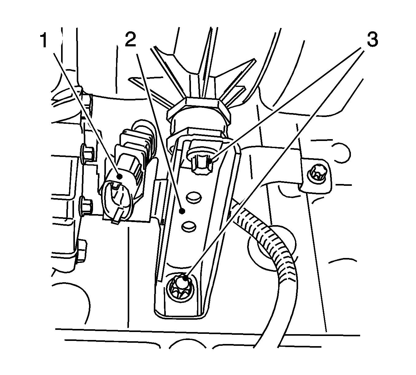
- Remove the intake manifold support (2).
| • | Disconnect the wiring harness plug of the catalytic converter control oxygen sensor. |
| • | Remove the wiring harness plug (1) from the bracket. |
| • | Remove the 2 bolts (3). |
- Remove the wiring harness from the intake manifold.
- Lower the vehicle by its full height.
- Remove the air cleaner housing. Refer to
Air Cleaner Assembly Replacement
.

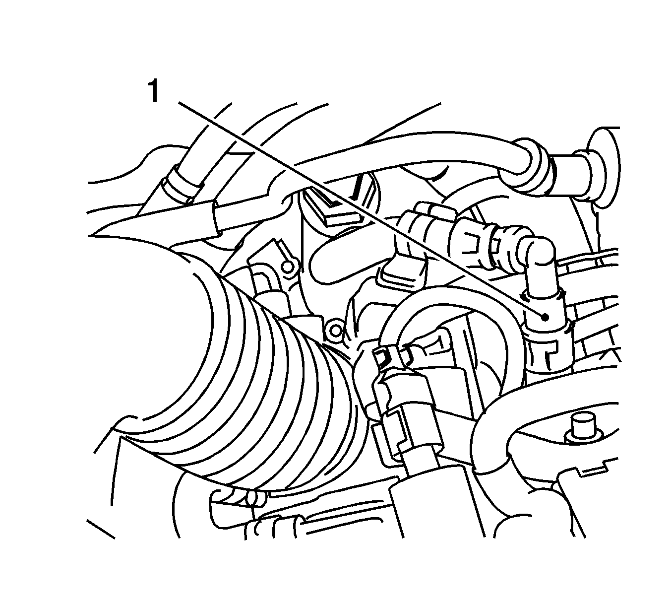
- Disconnect the tank vent valve from the intake manifold.
| • | Disconnect the wiring harness plug (2). |
| • | Disconnect the rubber mounting (3) from the bracket. |
| • | Disconnect the line (1) from the intake manifold. |
| • | Set the tank vent valve aside. |
- Place a drip pan underneath.

- Release the fuel pressure via the test connection (1) using
KM-J-34730-91
.
Collect exiting fuel in a suitable
container - observe safety regulations and national legislation.

- Remove the fuel return line (1).
| • | Remove the quick-release fitting with
J 37088-A
. |
| • | Seal the fuel line and fuel rail with
KM-807
. |

- Remove the engine venting pipe (1).
| • | Remove the wiring trough (2) from cylinder head cover. |
| • | Disconnect the 2 quick-release fittings. |
- Remove the engine control module. Refer to
Engine Control Module Replacement
.
- Remove the engine management wiring harness.
| • | Disconnect the 7 wiring harness plugs. |
| - | Valve, intake camshaft adjustment |
| • | Remove the 2 wiring harness brackets. |
| • | Put the wiring harness to side. |

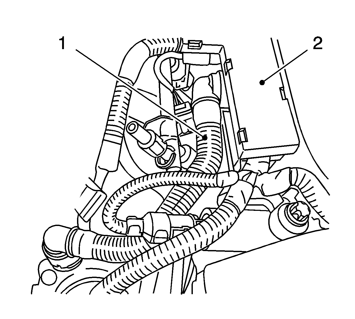
- Disconnect the wiring harness plug (1).

- Remove the supply line, fuel/air mixture preheating (1).
| • | Disconnect from thermostat housing. |
| • | Disconnect the quick-release fitting. |
| • | Disconnect from the throttle valve module. |
| • | Disconnect from the intake manifold. |
- Remove the return line, fuel/air mixture preheating (2).
| • | Remove from the throttle valve module. |
| • | Remove from the coolant expansion tank. |
| • | Remove from the intake manifold. |

- Disconnect the 2 wiring harness plugs.
| • | Wiring harness plug, vacuum unit change-over valves (1) |
| • | Wiring harness plug, change-over valves for solenoid valve (2) |

- Disconnect the wiring harness bracket (1) from the engine transport shackle.
Remove the bolt (2).

- Disconnect the brake servo vacuum line (1) from the intake manifold.
Disconnect the quick-release fitting.

- Remove the throttle valve module.
Remove the 4 bolts (1).

- Remove the intake manifold.
Remove the 7 bolts (1).
- Remove the wiring harness bracket.
Remove the 2 bolts.
- Fuel rail system
Installation Procedure
- Clean the sealing surfaces.
- Insert the 4 new gaskets.
Notice: Refer to Fastener Notice in the Preface section.
- Install the intake manifold.
Tighten
Tighten the 7 bolts to 20 N·m (16 lb ft).
- Install the throttle valve module.
Use a new gasket.
Tighten
Tighten the 4 bolts to 9 N·m (80 lb in).
- Install the brake servo vacuum line to the intake manifold.
Connect the quick release fitting.
- Install the wiring harness bracket to the engine transport shackle.
Tighten
Tighten the bolt to 5 N·m (44 lb in).
- Connect the 2 wiring harness plugs.
| • | Vacuum unit change-over valves |
| • | Solenoid valve for change-over valves |
- Install the return line, fuel/air mixture preheating.
| • | Connect the throttle valve module. |
| • | Connect the coolant expansion tank. |
| • | Install the intake manifold. |
| • | Install the 3 brackets. |
- Install the supply line, fuel/air mixture preheating.
| • | Connect to the thermostat housing. |
| • | Connect the quick release fitting. |
| • | Install the throttle valve module. |
| • | Install the intake manifold. |
| • | Connect the 4 brackets. |
- Install the engine management wiring harness.
| • | Connect the 7 wiring harness plugs. |
| - | Valve, intake camshaft adjustment |
| • | Clip on the 2 wiring harness brackets. |
- Install the engine control module. Refer to
Engine Control Module Replacement
.
- Install the engine vent hose.
| • | Connect the 2 quick-release fittings. |
| • | Clip the wiring harness to the cylinder head. |
- Install the fuel supply line to the fuel rail.
| • | Connect the quick release fitting. |
| • | Install into the bracket. |
- Connect the tank vent valve to the intake manifold.
| • | Connect the line to the intake manifold. |
| • | Connect the rubber mounting to the bracket. |
| • | Install the wiring harness plug. |
- Install the air cleaner housing. Refer to
Air Cleaner Assembly Replacement
.
- Raise the vehicle by its full height.
- Install the wiring harness to the intake manifold.
- Install the intake manifold support.
Tighten
Tighten the 2 bolts to 8 N·m (71 lb in).
| • | Connect the wiring harness plug into the bracket. |
| • | Connect the wiring harness plug for the catalytic converter control oxygen sensor. |
- Lower the vehicle by its full height.
- Fill and bleed the cooling system. Refer to
Cooling System Draining and Filling
.
- Connect the battery.
- For programming procedures, refer to
Control Module References
.
- Close the hood.


