Camshaft Replacement First Design
Removal Procedure
- Remove the engine. Refer to Engine Replacement .
- Remove the crankshaft balancer. Refer to Crankshaft Balancer Removal .
- Remove the oil level indicator. Refer to Oil Level Indicator and Tube Removal .
- Remove the left and right exhaust manifolds. Refer to Exhaust Manifold Removal - Left Side and Exhaust Manifold Removal - Right Side .
- Remove the water pump. Refer to Water Pump Removal .
- Remove the coolant pump manifold. Refer to Coolant Pump Manifold Replacement .
- Remove the intake manifold. Refer to Intake Manifold Removal .
- Remove the valve lifter oil manifold. Refer to Valve Lifter Oil Manifold Removal .
- Remove the coolant air bleed pipe. Refer to Coolant Air Bleed Pipe Removal .
- Remove the left and right valve rocker arm covers. Refer to Valve Rocker Arm Cover Removal - Left Side and Valve Rocker Arm Cover Removal - Right Side .
- Remove the valve rocker arms and pushrods. Refer to Valve Rocker Arm and Push Rod Removal .
- Remove the valve lifters. Refer to Valve Lifter Removal .
- Remove the oil pan-to-front cover bolts.
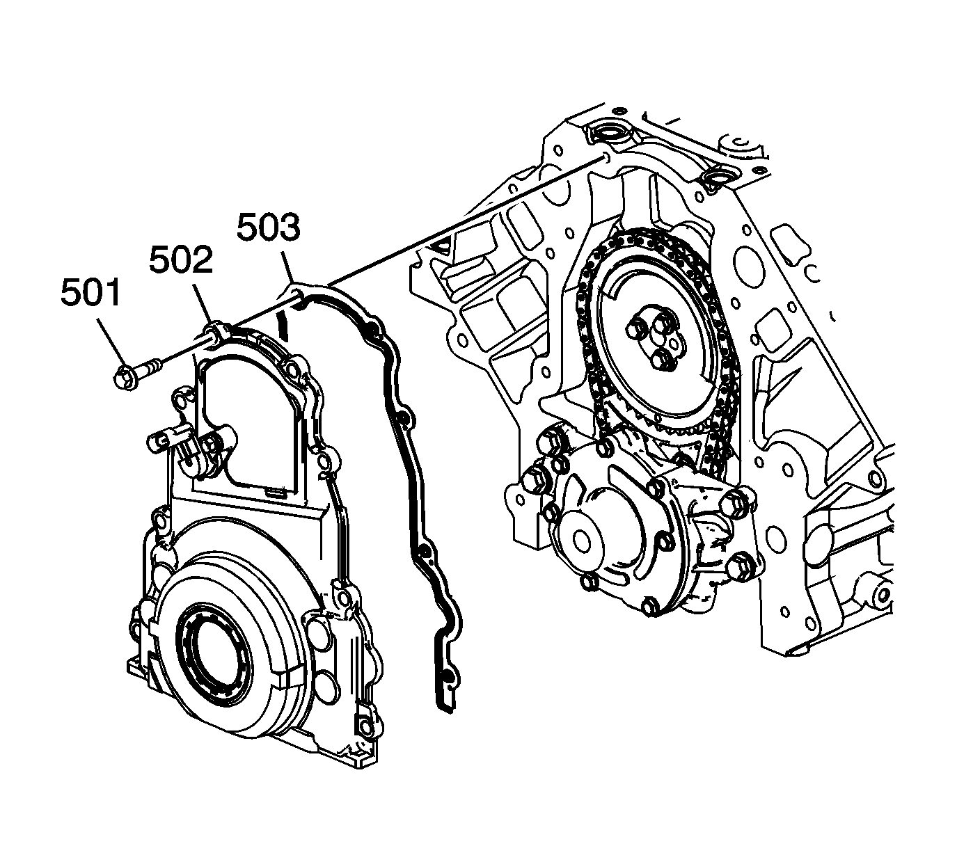
- Remove the front cover bolts (501).
- Remove the front cover (502) and gasket (503).
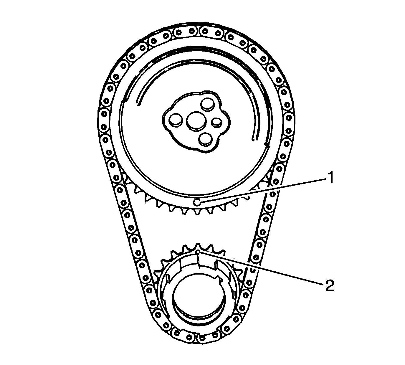
- Rotate the crankshaft in order to align the timing marks (1, 2).
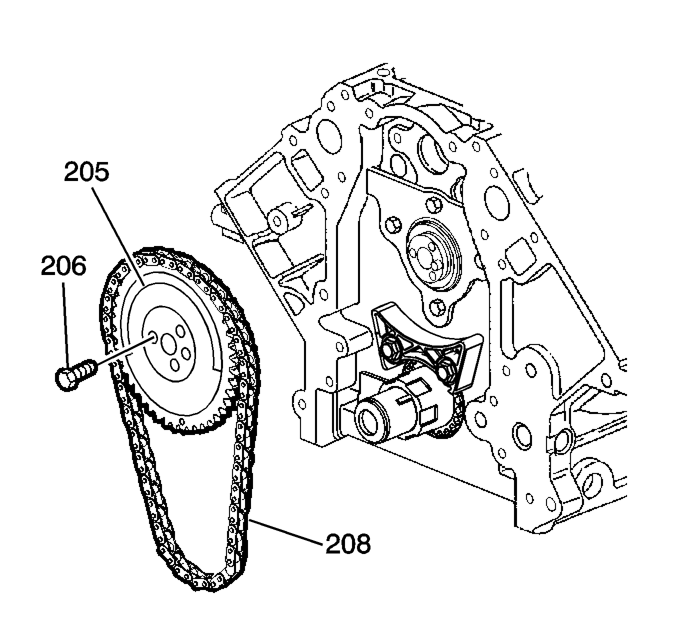
- Remove the camshaft sprocket bolts (206).
- Remove the camshaft sprocket (205) and timing chain (208).
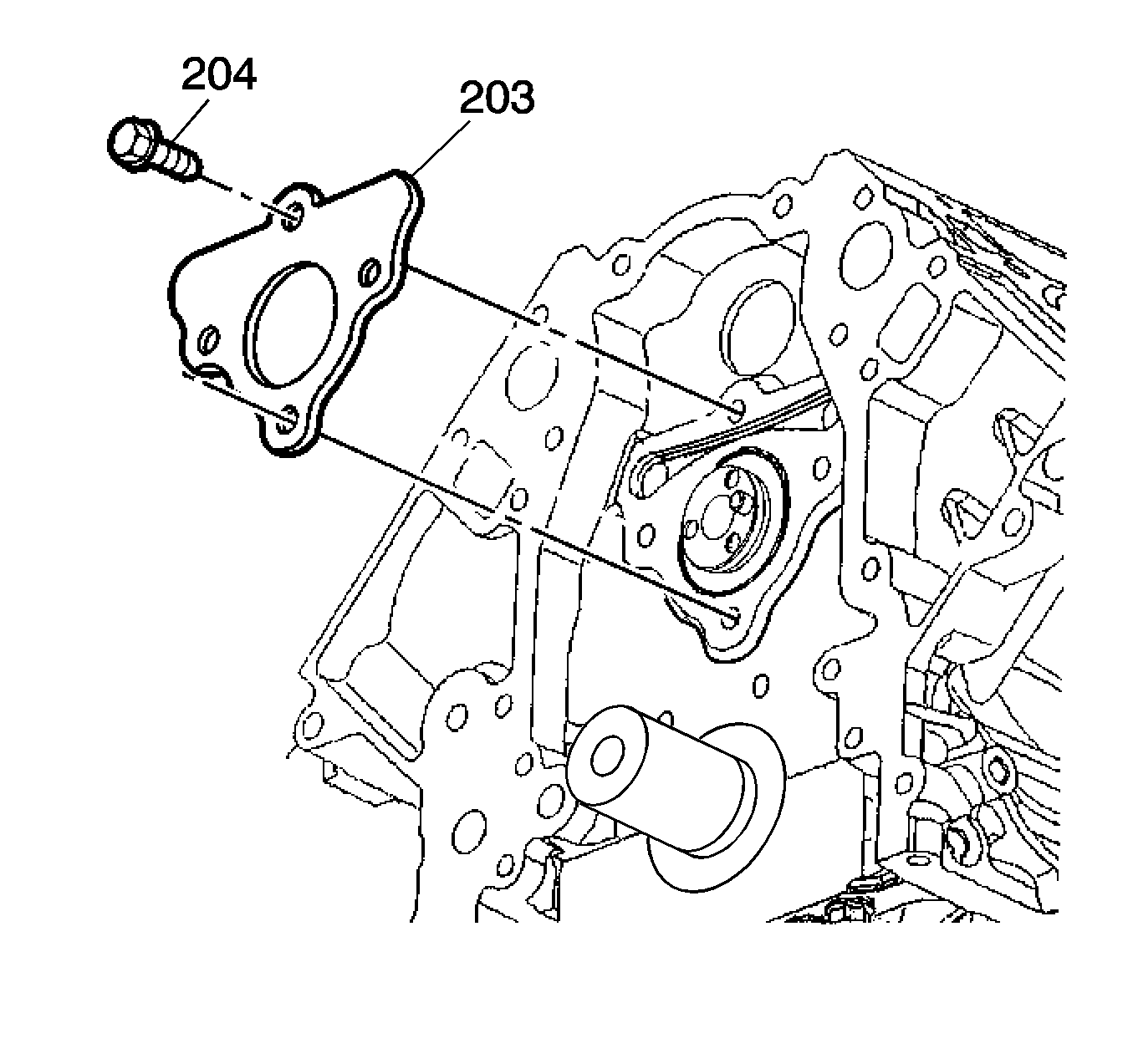
- Remove the camshaft retainer bolts (204) and retainer (203).
- Remove the camshaft.
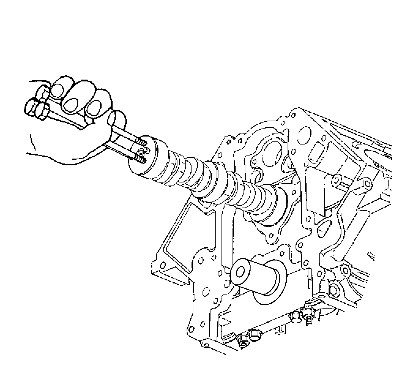
| 20.1. | Install 3 M8-125 x 100 mm bolts in the camshaft front bolt holes. |
| 20.2. | Using the bolts as a handle, carefully rotate and pull the camshaft out of the engine block. |
| 20.3. | Remove the bolts from the camshaft. |
Installation Procedure
Important: If camshaft replacement is required, the valve lifters must also be replaced.
- Lubricate the camshaft journals and the bearings with clean engine oil.
- Install 3 M8-125 x 100 mm bolts in the NEW camshaft front bolt holes.
- Using the bolts as a handle, carefully install the NEW camshaft into the engine block.
- Remove the 3 bolts from the camshaft.
- Install the camshaft retainer (203) and bolts (204).
- Install the camshaft sprocket (205) and timing chain (208). If necessary, rotate the camshaft or crankshaft sprocket in order to align the timing marks.
- Install the camshaft sprocket bolts (206).
- Inspect the camshaft (1) and crankshaft (2) sprockets for proper timing mark alignment.
- Install the front cover (502) . Refer to Engine Front Cover Installation .
- Install the oil pan-to-front cover bolts.
- Install the valve lifters. Refer to Valve Lifter Installation .
- Install the valve rocker arms and pushrods. Refer to Valve Rocker Arm and Push Rod Installation .
- Install the left and right valve rocker arm covers. Refer to Valve Rocker Arm Cover Installation - Left Side and Valve Rocker Arm Cover Installation - Right Side .
- Install the coolant air bleed pipe. Refer to Coolant Air Bleed Pipe Installation .
- Install the valve lifter oil manifold. Refer to Valve Lifter Oil Manifold Installation .
- Install the intake manifold. Refer to Intake Manifold Installation .
- Install the coolant pump manifold. Refer to Coolant Pump Manifold Replacement .
- Install the water pump. Refer to Water Pump Installation .
- Install the left and right exhaust manifolds. Refer to Exhaust Manifold Installation - Left Side and Exhaust Manifold Installation - Right Side .
- Install the oil level indicator. Refer to Oil Level Indicator and Tube Installation .
- Install the crankshaft balancer. Refer to Crankshaft Balancer Installation .
- Install the engine. Refer to Engine Replacement .

Notice: Refer to Fastener Notice in the Preface section.

Important:
• Install the retainer plate with the sealing gasket facing the engine block. • The gasket surface on the engine block should be clean and free of dirt or debris.
Tighten
Tighten the bolts to 25 N·m (18 lb ft).

Important:
• Properly locate the camshaft sprocket onto the locating pin of the camshaft. • The sprocket teeth and timing chain teeth must mesh. • The camshaft and crankshaft sprocket alignment marks MUST be aligned properly. Position the camshaft sprocket alignment mark in the 6 o'clock position.
Tighten
Tighten the bolts to 25 N·m (18 lb ft).


Tighten
Tighten the bolts to 25 N·m (18 lb ft).
