Tools Required
| • | J 38185 Hose Clamp Pliers |
| • | J 39580 Universal Engine Support Table |
Removal Procedure
- Disconnect the negative battery cable. Refer to Battery Negative Cable Disconnection and Connection .
- Remove the engine sight shield. Refer to Upper Intake Manifold Sight Shield Replacement .
- Evacuate the air conditioning (A/C) system. Refer to Refrigerant Recovery and Recharging .
- Remove the front tires and wheels. Refer to Tire and Wheel Removal and Installation .
- Drain the cooling system. Refer to Cooling System Draining and Filling .
- Drain the engine oil. Refer to Engine Oil and Oil Filter Replacement .
- Lower the vehicle.
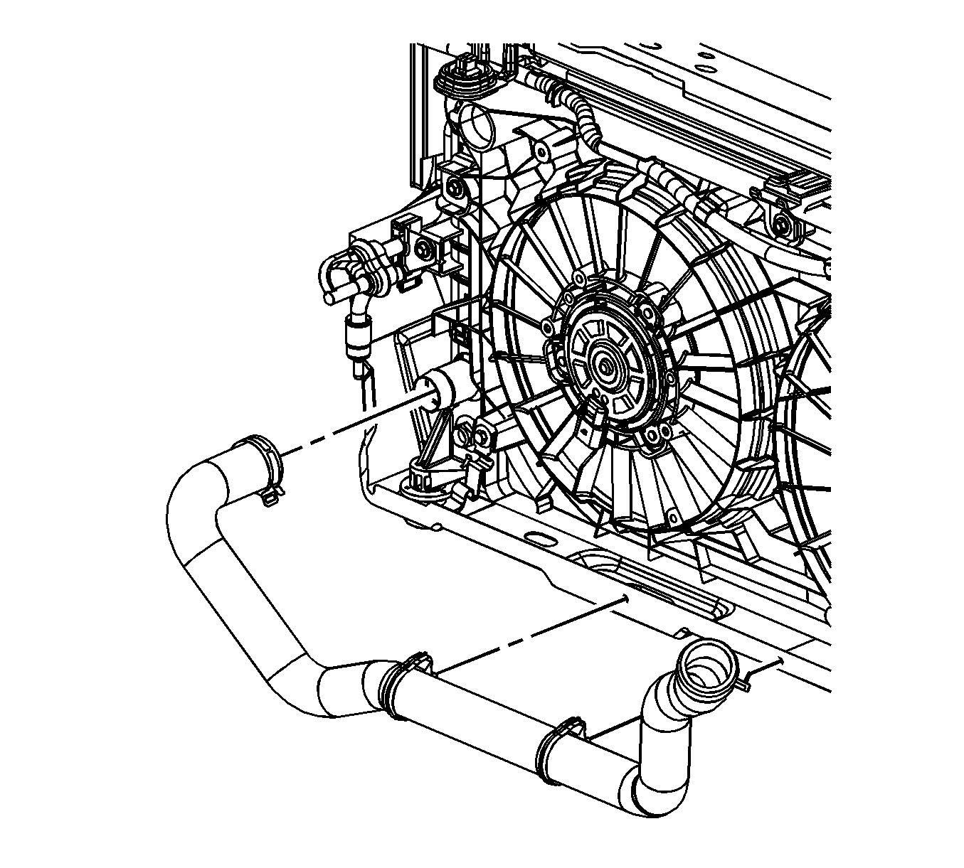
- Using the J 38185 reposition the inlet hose clamp at the radiator.
- Remove the inlet hose from the radiator.
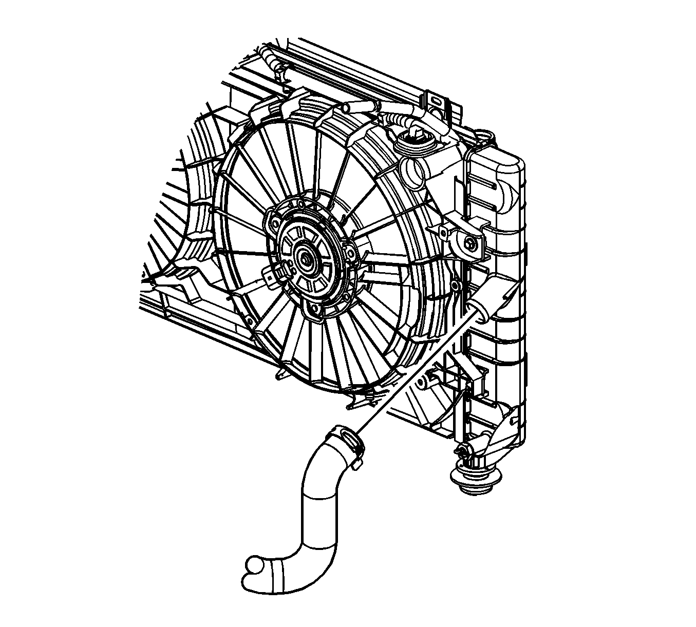
- Using the J 38185 reposition the outlet hose clamp at the radiator.
- Disengage the outlet hose clips from the fan shroud.
- Remove the outlet hose from the radiator.
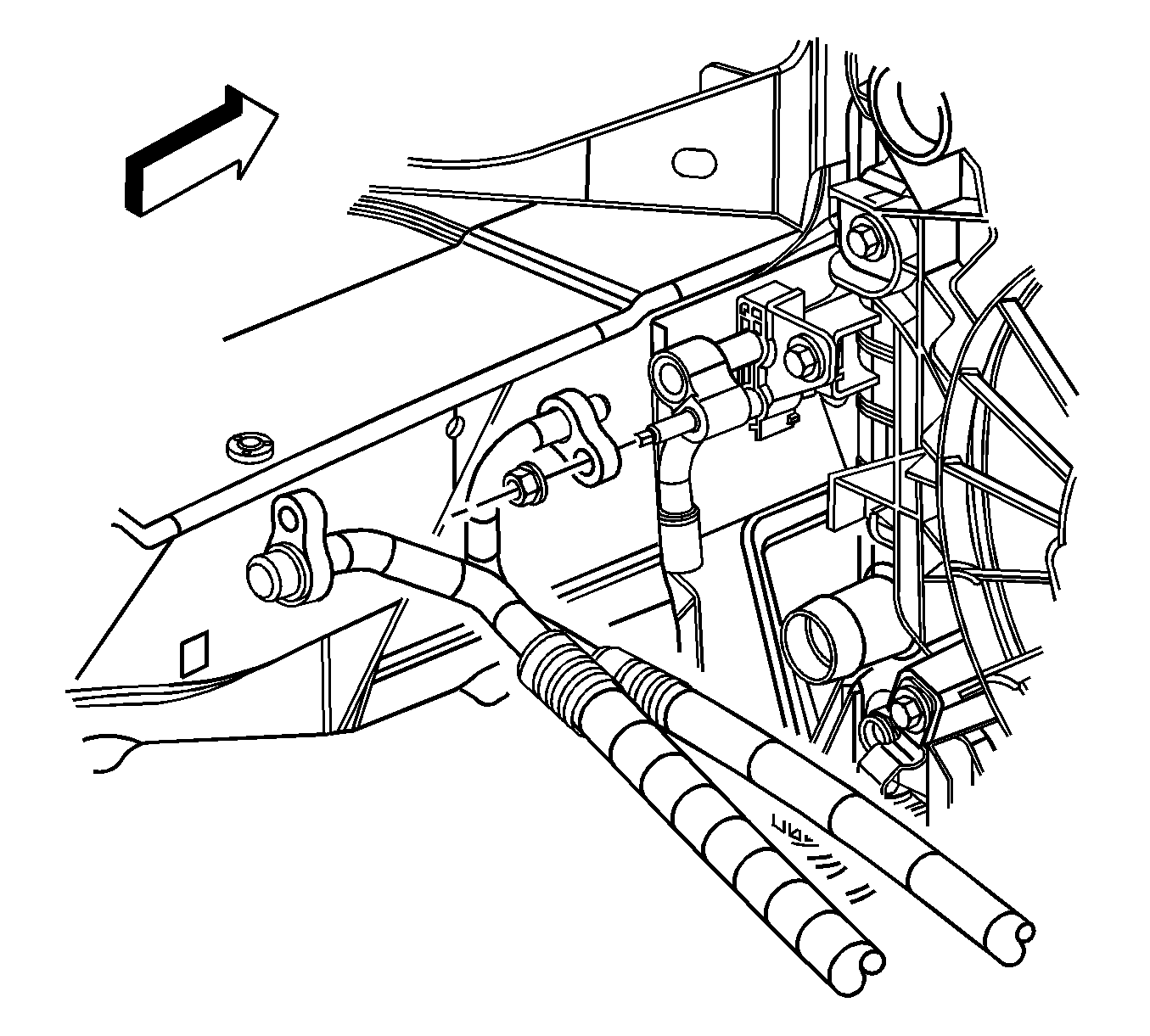
- Remove the A/C compressor hose nut at the A/C receiver/dehydrator tube.
- Remove the A/C compressor hose.
- Remove the A/C compressor hose nut at the A/C condenser.
- Remove the A/C compressor hose.
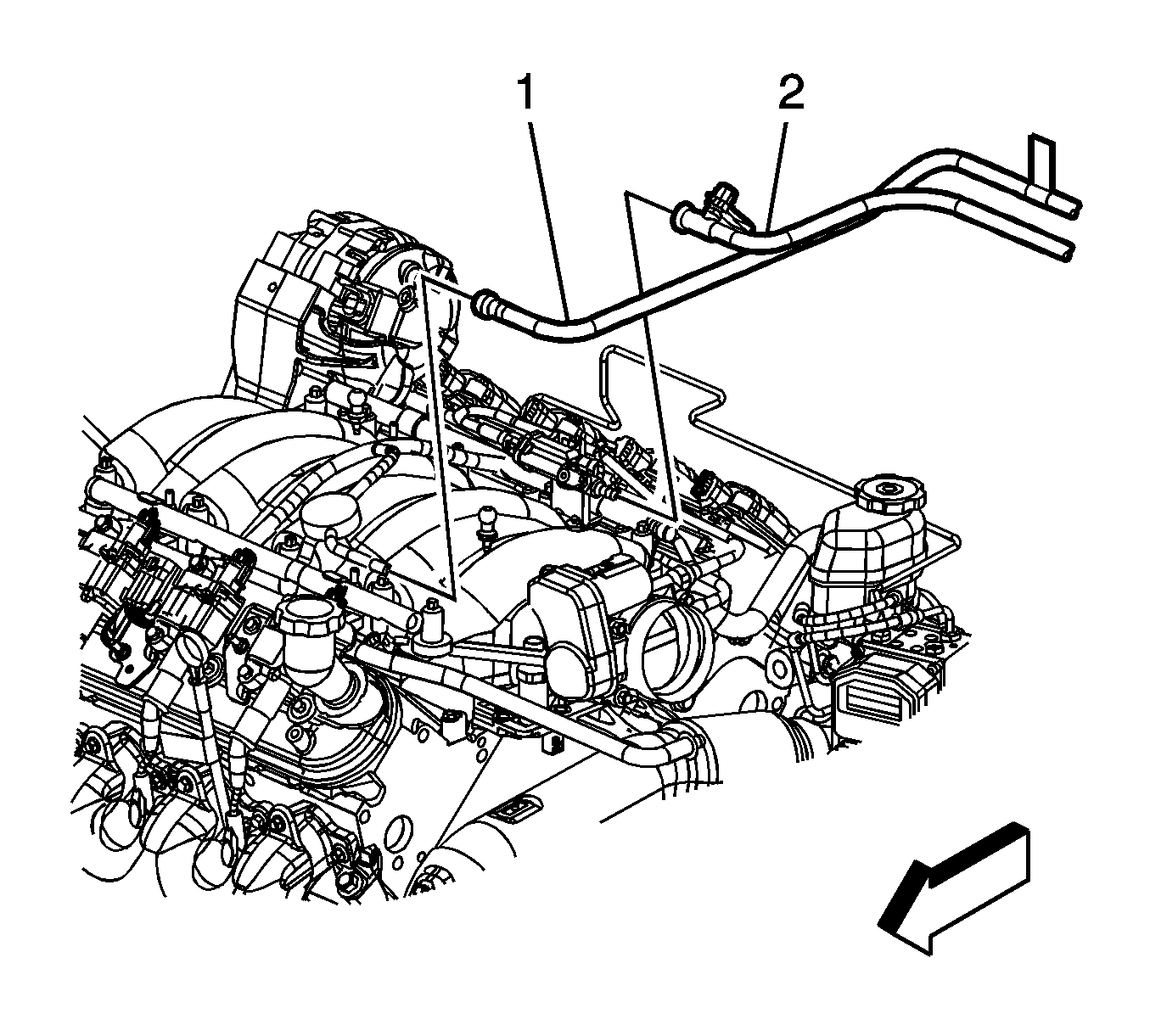
- Remove the brake booster vacuum hose from the brake booster (3).
- Remove the brake booster vacuum hose (1) from the intake manifold (2).
- Disconnect the engine harness electrical connectors (1, 2) from the instrument panel (I/P) harness electrical connectors.
- Disconnect the brake fluid level switch electrical connector (3) from the master cylinder.
- Remove brake fluid from the master cylinder.
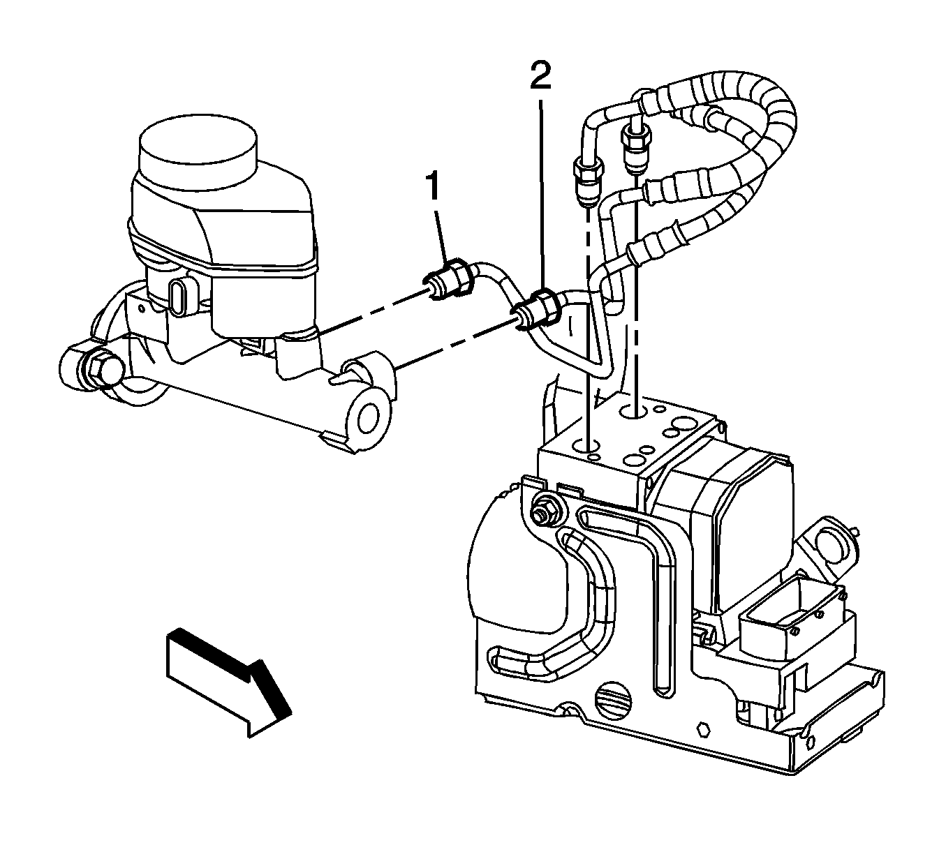
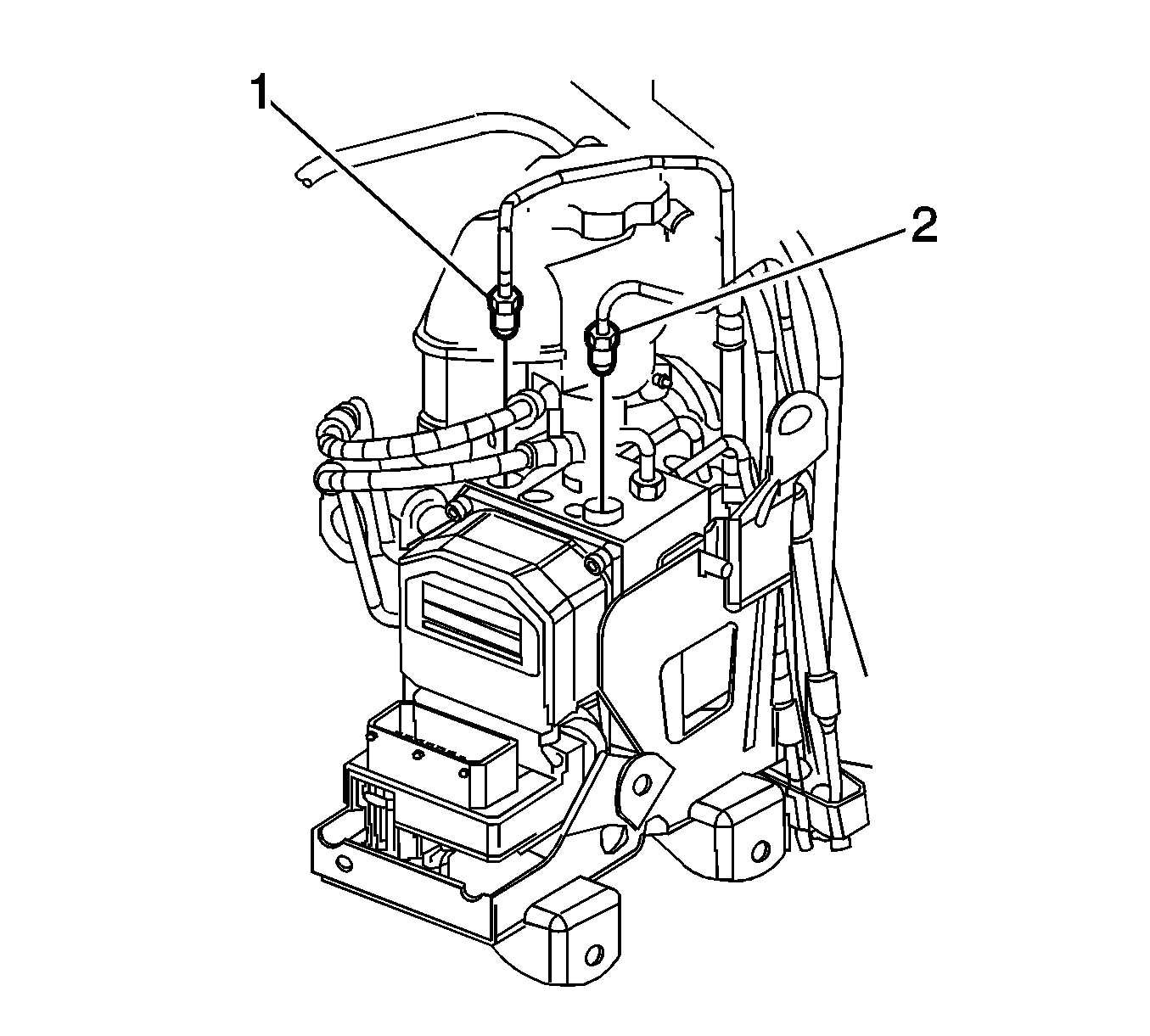
- Disconnect the from brake pipe fittings (1, 2) from the master cylinder.
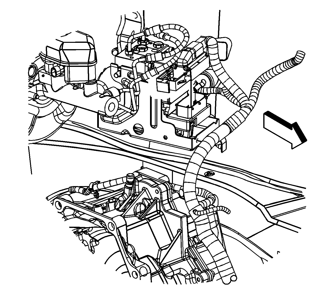
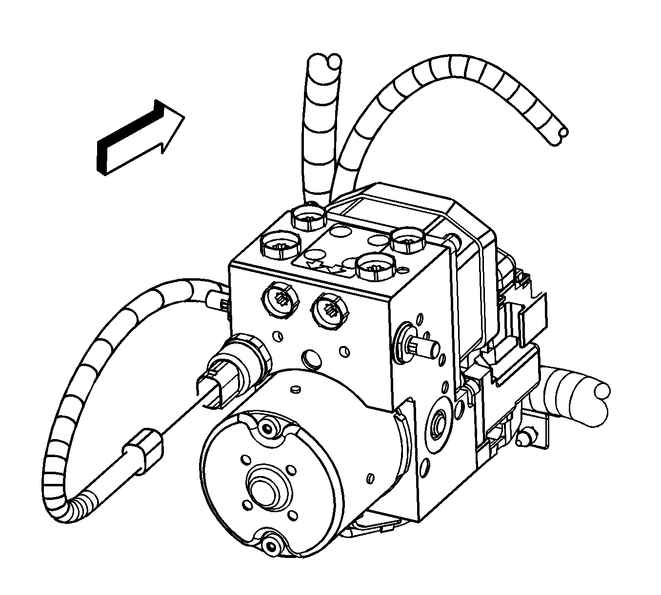
- Disconnect the brake pipe fittings (1, 2) from the antilock brake (ABS) module.
- Remove the master cylinder nuts.
- Position the master cylinder to the engine. Hold the master cylinder in place using mechanic's wire.
- Relieve the fuel system pressure. Refer to Fuel Pressure Relief .
- Disconnect the fuel feed line (1) from the fuel rail. Refer to Metal Collar Quick Connect Fitting Service .
- Disconnect the evaporative emission (EVAP) line (2) from the purge solenoid. Refer to Plastic Collar Quick Connect Fitting Service .
- Remove the right front fender diagonal brace. Refer to Front Fender Upper Diagonal Brace Replacement .
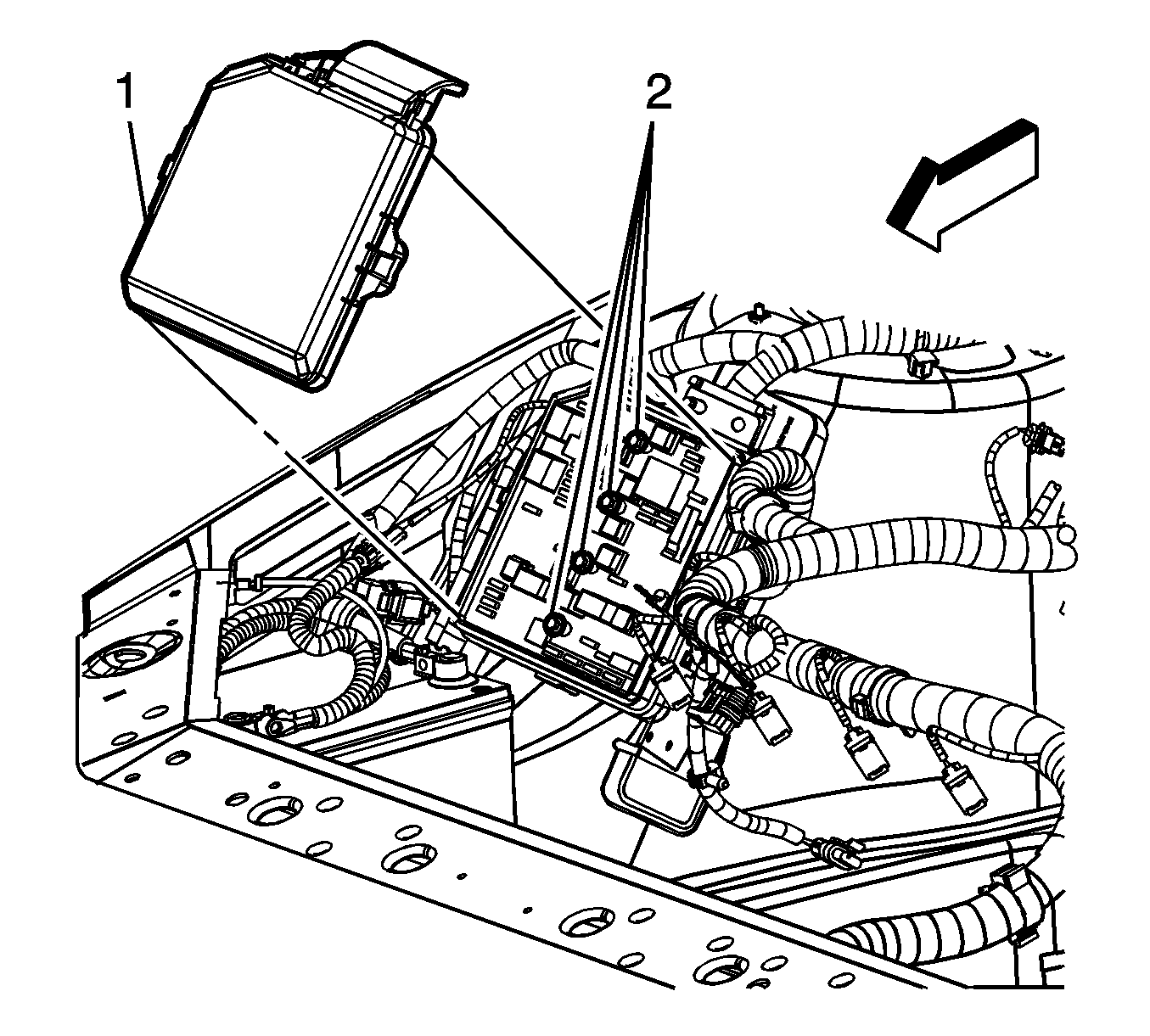
- Remove the underhood electrical center cover (1).
- Loosen the 4 integral bolts (2) attaching the fuse block. Reposition the fuse block.
- Loosen the engine harness connector bolt (1). Remove the engine harness connector from the bracket.
- Disconnect the camshaft position sensor lead.
- Disconnect the engine harness electrical connector from the ABS module.
- Disconnect the engine harness electrical connector from the electronic brake control module (EBCM).
- Remove the air cleaner assembly. Refer to Air Cleaner Element Replacement .
- Disconnect the following electrical connectors:
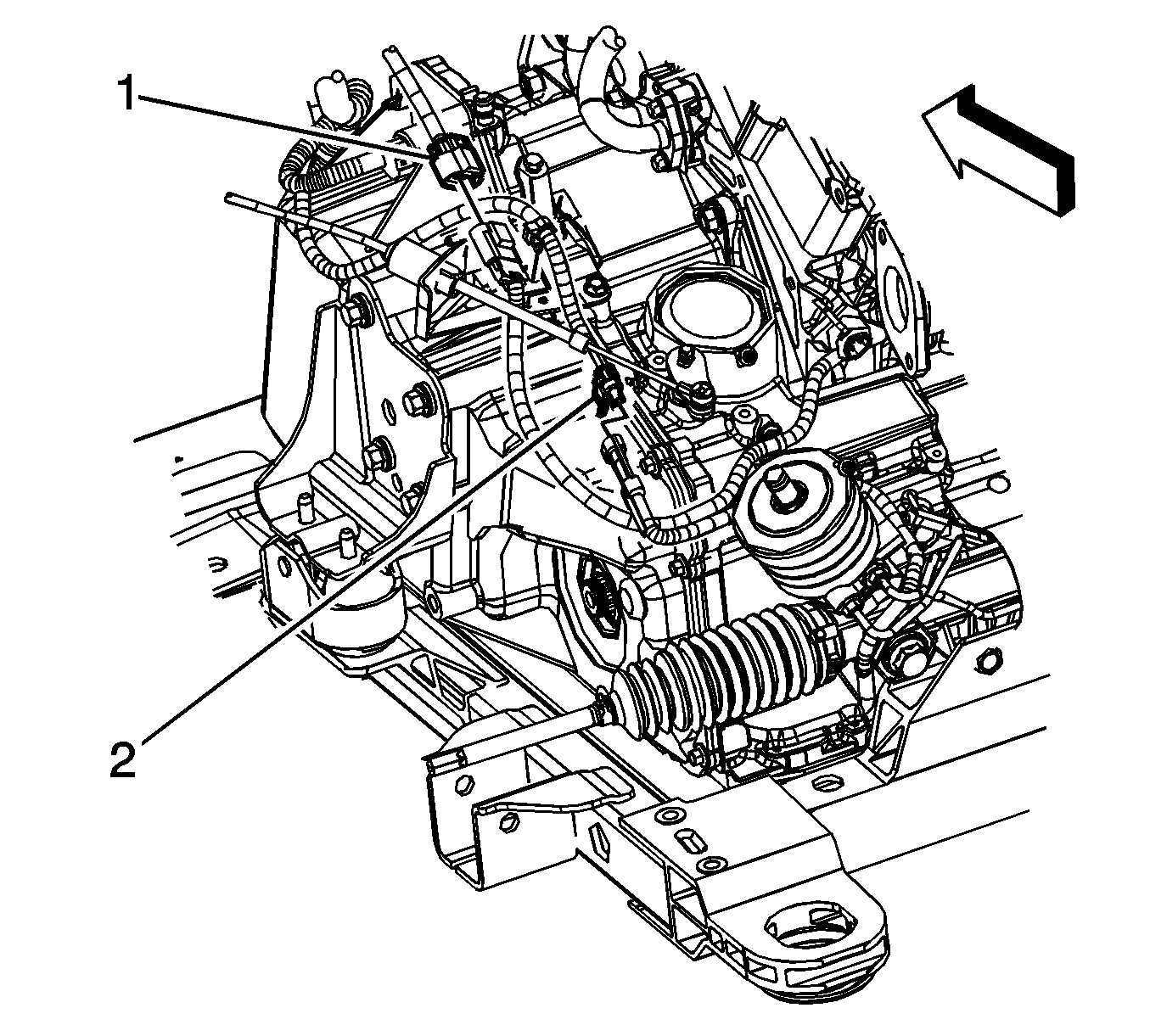
- Disconnect the engine harness electrical connector (1) from the crankshaft position (CKP) sensor harness.
- Disconnect the engine harness electrical connector (2) from the power steering gear harness.
- Remove the clip attaching the power steering gear harness to the bracket.
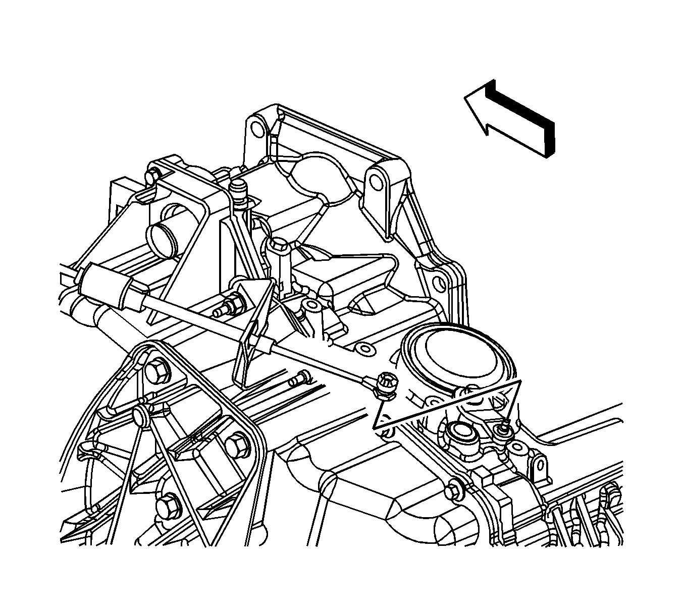
- Remove the shift cable clip.
- Disconnect the shift cable from the transaxle selector lever stud.
- Remove the shift cable from the bracket.
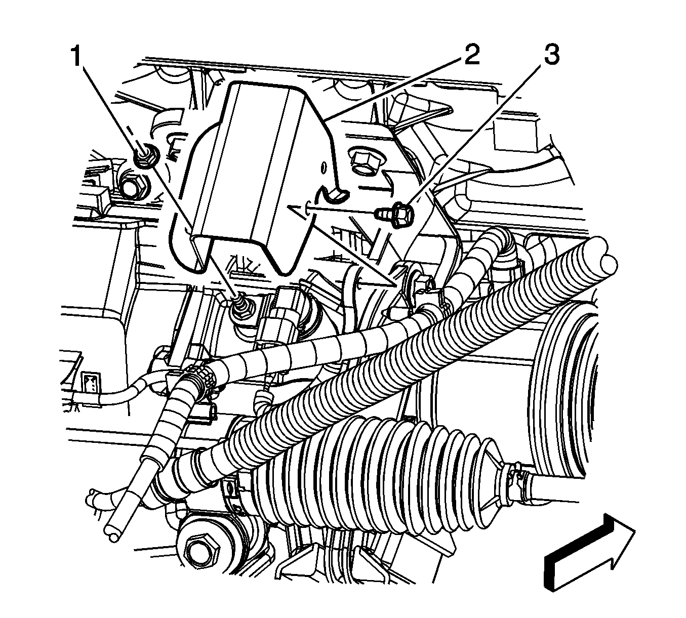
- Remove the vehicle speed sensor (VSS) shield nut (1) and bolt (3). Remove the shield (2).
- Disconnect the engine harness electrical connector from the VSS.
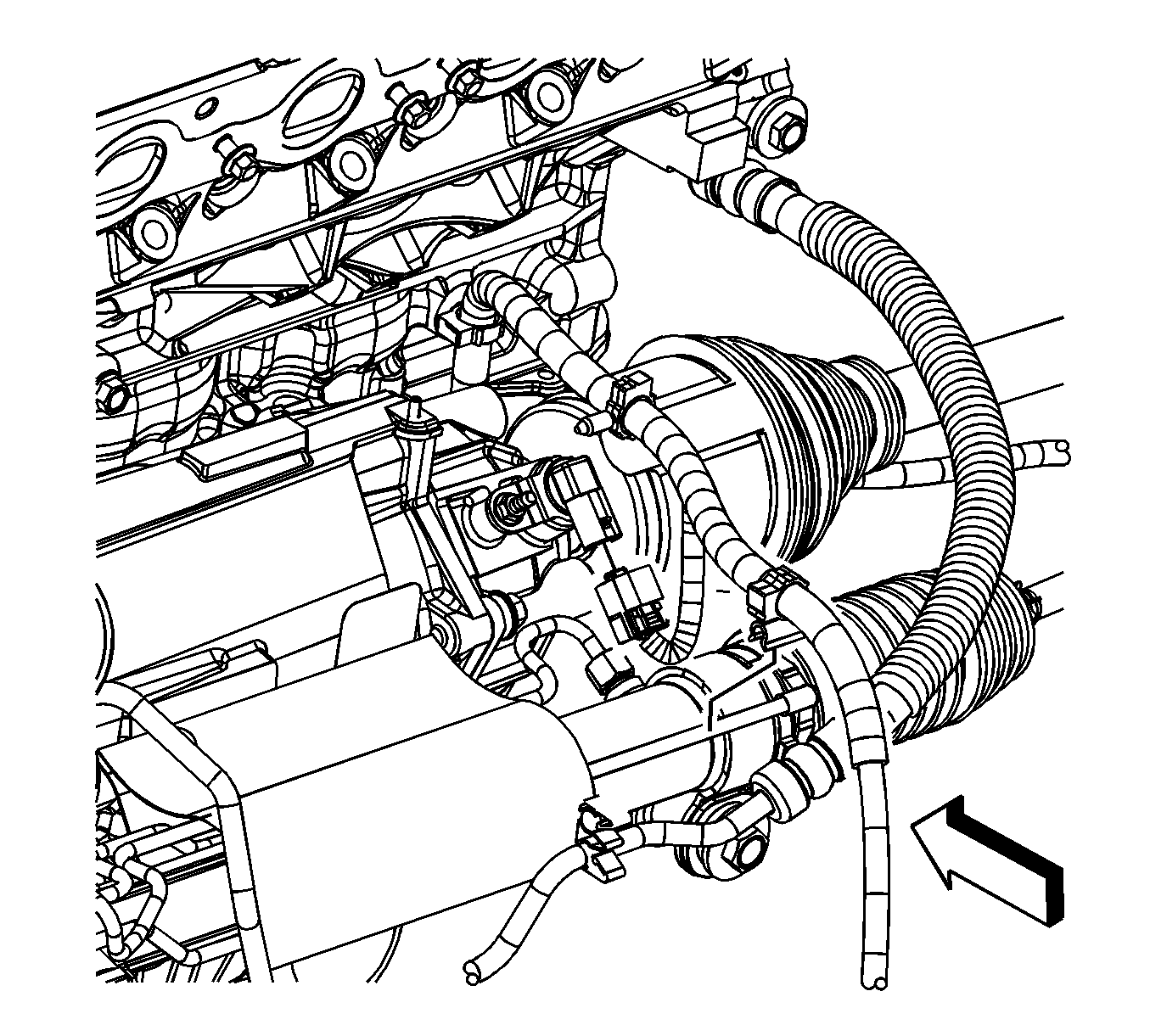
- Set all branches of the engine wiring harness on top of the engine.
- Reposition the intermediate shaft lower boot.
- Remove the intermediate shaft to steering gear bolt.
- Separate the intermediate shaft from the steering gear.
- Disconnect both front wheel speed sensors. Refer to Front Wheel Bearing and Hub Replacement .
- Unclip the ABS wire harness from the lower control arm.
- Using the J 38185 reposition the heater inlet and outlet hose clamps.
- Remove the heater inlet (2) and outlet (1) hoses from the heater inlet/outlet pipe.
- Raise and support the vehicle. Refer to Lifting and Jacking the Vehicle .
- Disconnect the stabilizer links from the stabilizer shaft.
- Disconnect the ball joints from the steering knuckles. Refer to Lower Control Arm Ball Joint Replacement .
- Disconnect the power steering pressure hose from the steering gear.
- Disconnect the power steering pressure line clips from the frame.
- Disconnect the outer tie rod ends from the steering knuckles. Refer to Rack and Pinion Outer Tie Rod End Replacement .
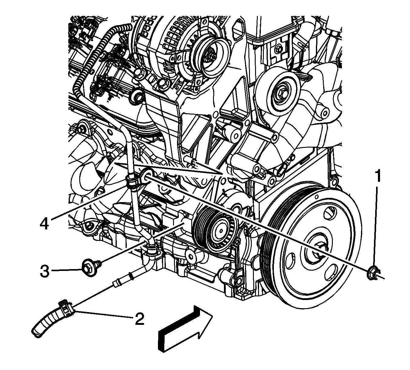
- Loosen the power steering hose clamp at the inlet pipe.
- Remove the power steering hose (2) from the inlet pipe.
- Remove the left and right wheel drive shafts from the transaxle. Refer to Wheel Drive Shaft Replacement .
- Support the wheel drive shafts using mechanic's wire.
- Remove the transaxle oil cooler line bracket bolt/stud.
- Disconnect the transaxle oil cooler lines from the transaxle. Refer to Transmission Fluid Cooler Hose/Pipe Quick-Connect Fitting Disconnection and Connection .
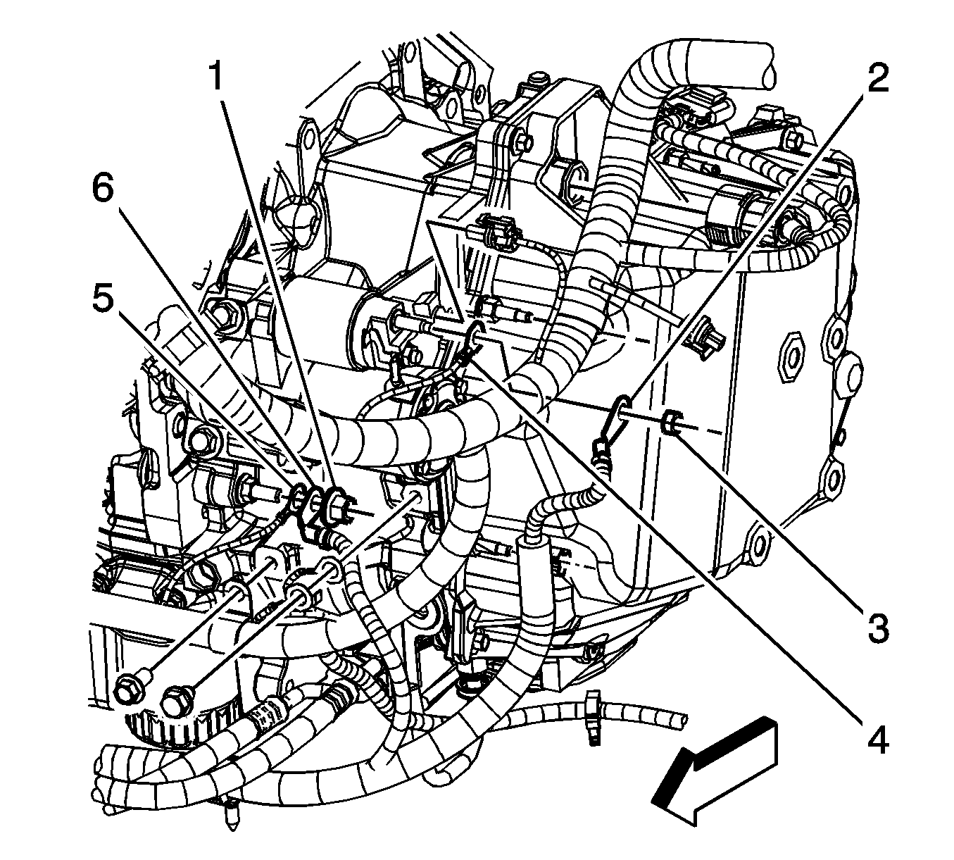
- Remove the positive battery cable nut (3) from the starter.
- Remove the cable terminal (2) from the starter.
- Remove the battery cable ground nut (1).
- Remove the cable ground terminal (6) from the stud.
- Remove the battery cable retainers from the engine frame.
- Disconnect the exhaust system. Refer to Catalytic Converter Replacement .
- Disconnect the O2 sensor harness pigtail.
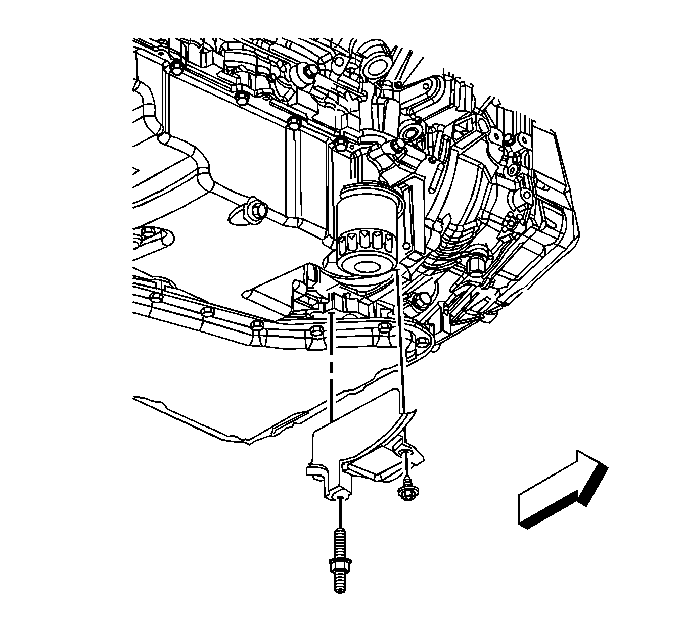
- Remove the transaxle converter cover bolt/stud.
- Remove the converter cover.
- Remove the flywheel bolts.
- Remove the front air deflectors. Refer to Radiator Air Lower Baffle and Deflector Replacement .
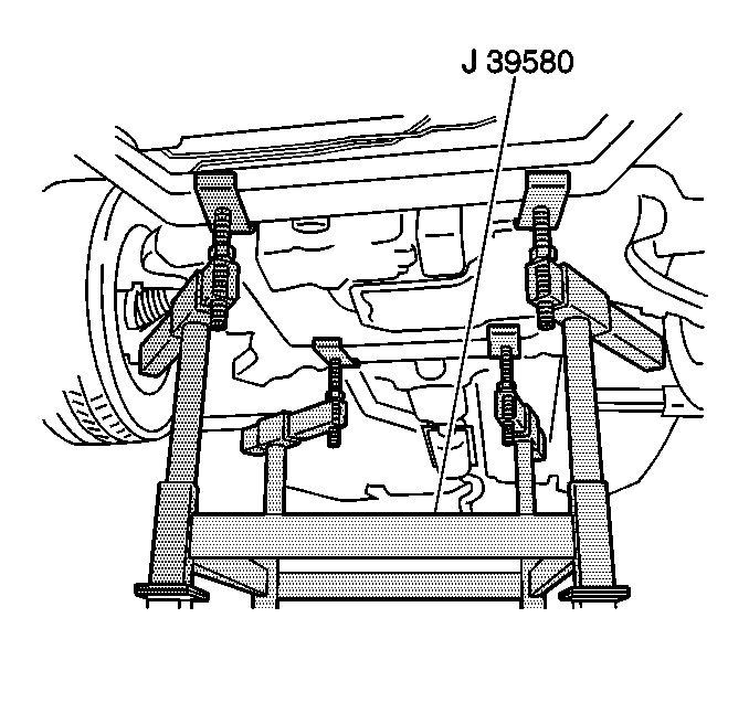
- Raise the vehicle enough to place J 39580 under the engine, frame, and front suspension.
- Support the rear of the vehicle with suitable jackstand.
- Strap the front of the vehicle to the hoist.
- Raise the J 39580 , or lower the vehicle to preload the weight of the engine, frame, and front suspension.
- Remove the radiator to frame brackets.
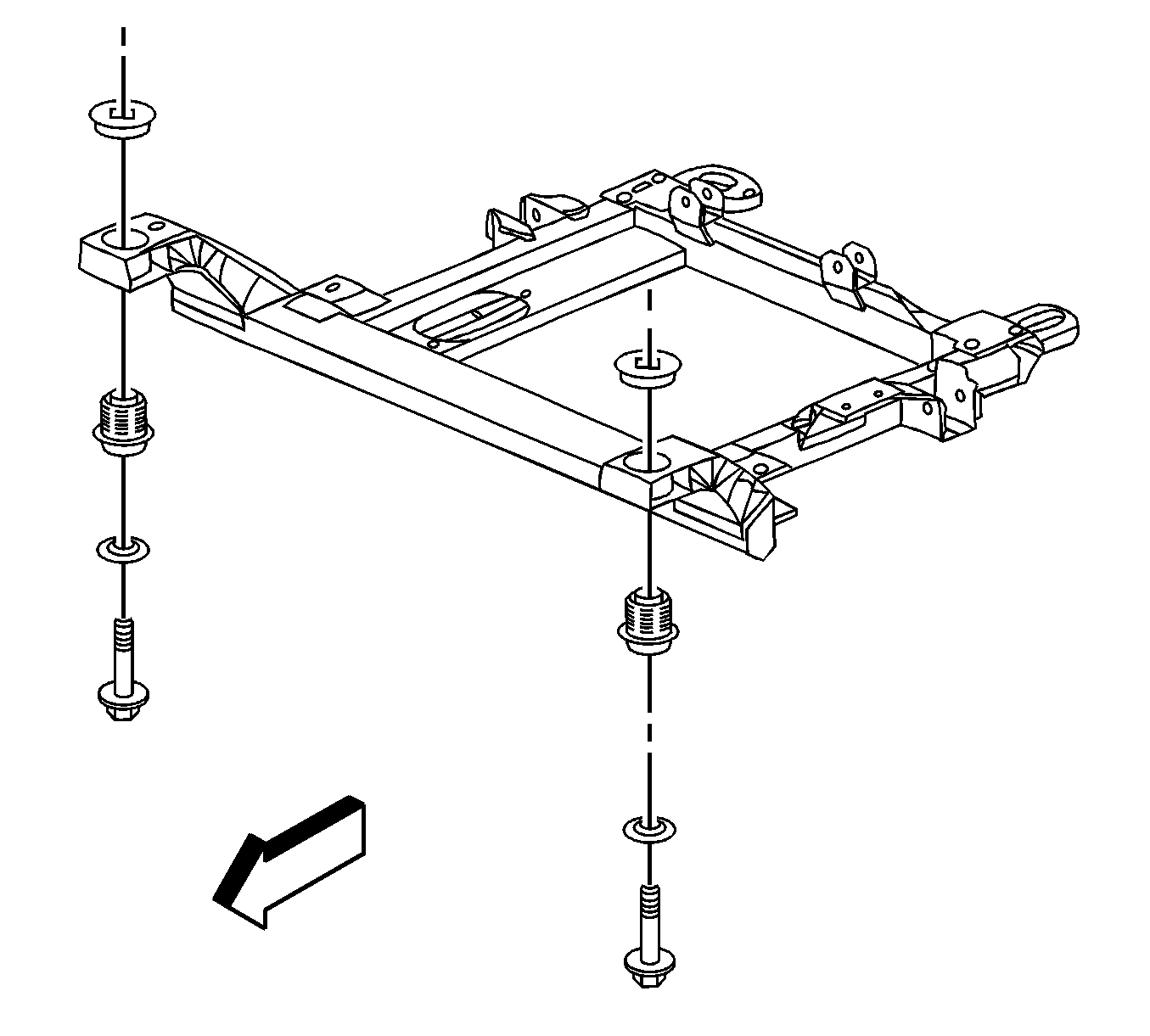
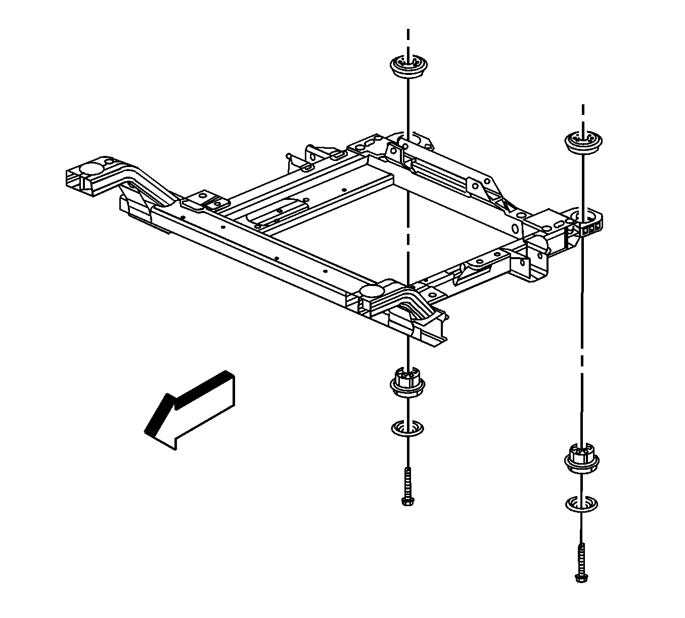
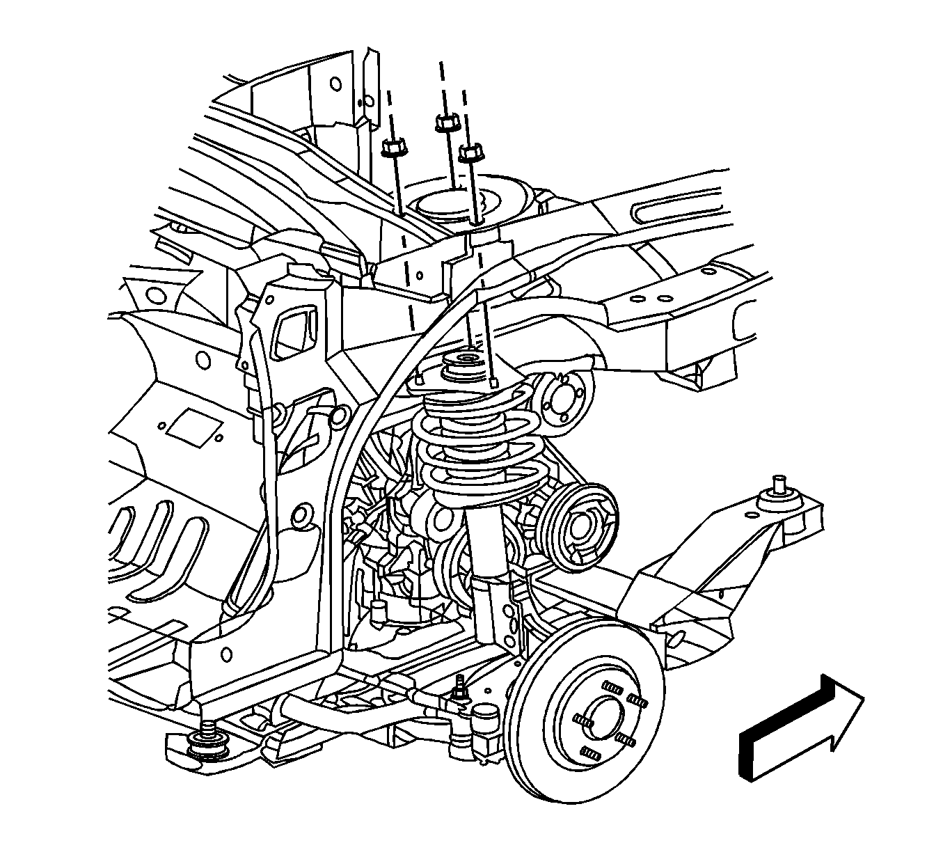
- Remove the engine frame front bolts.
- Remove the engine frame rear bolts.
- With the aid of an assistant, lower the J 39580 and/or raise the vehicle to remove the engine and the frame from the vehicle.
- Ensure that all hoses, wires, and pipes clear the vehicle during the removal process.
- Use a suitable engine lift to support the engine.
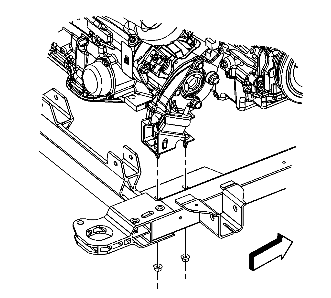
- Remove the front engine mount to frame nuts.
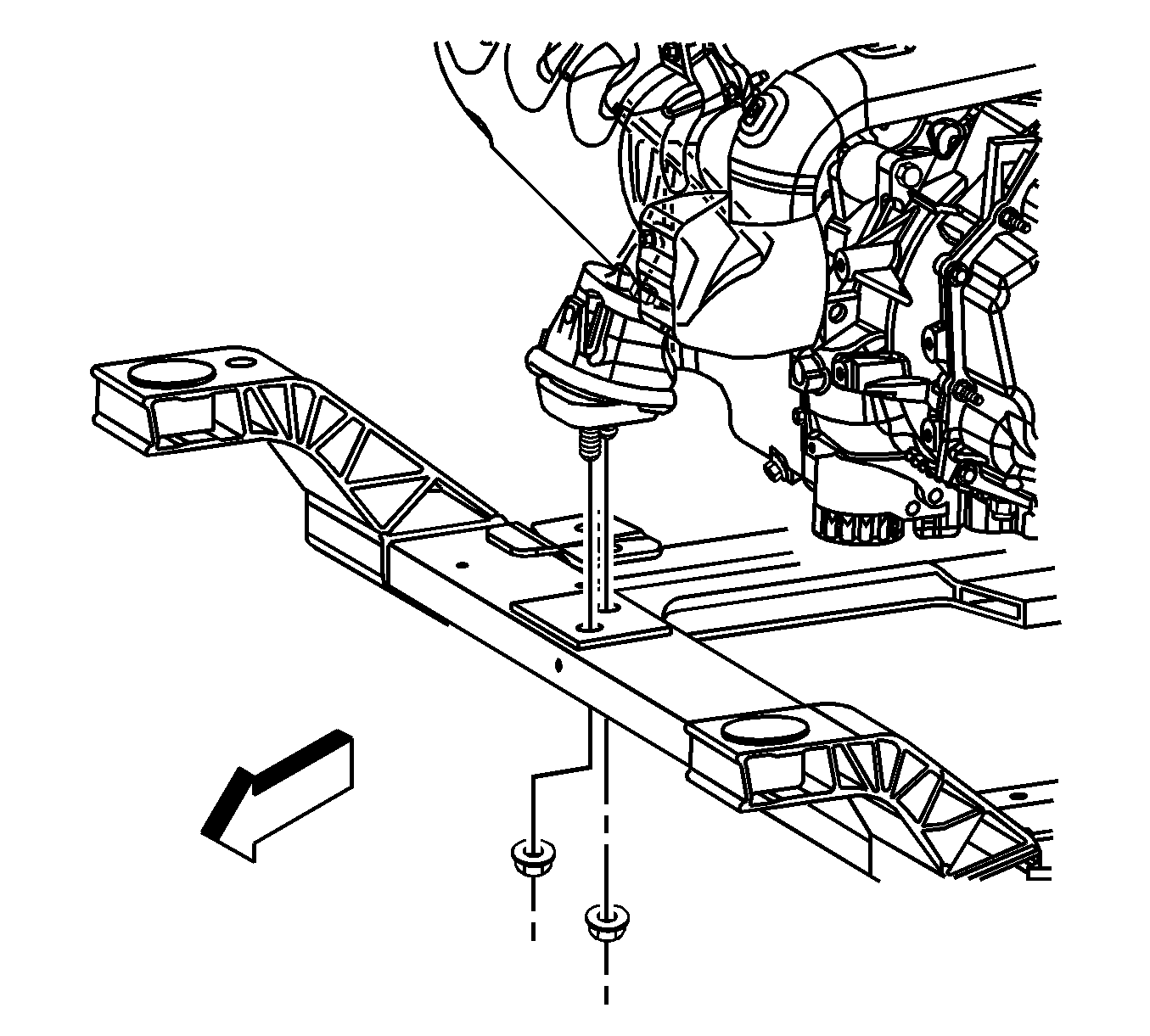
- Remove the rear engine mount to frame nuts.
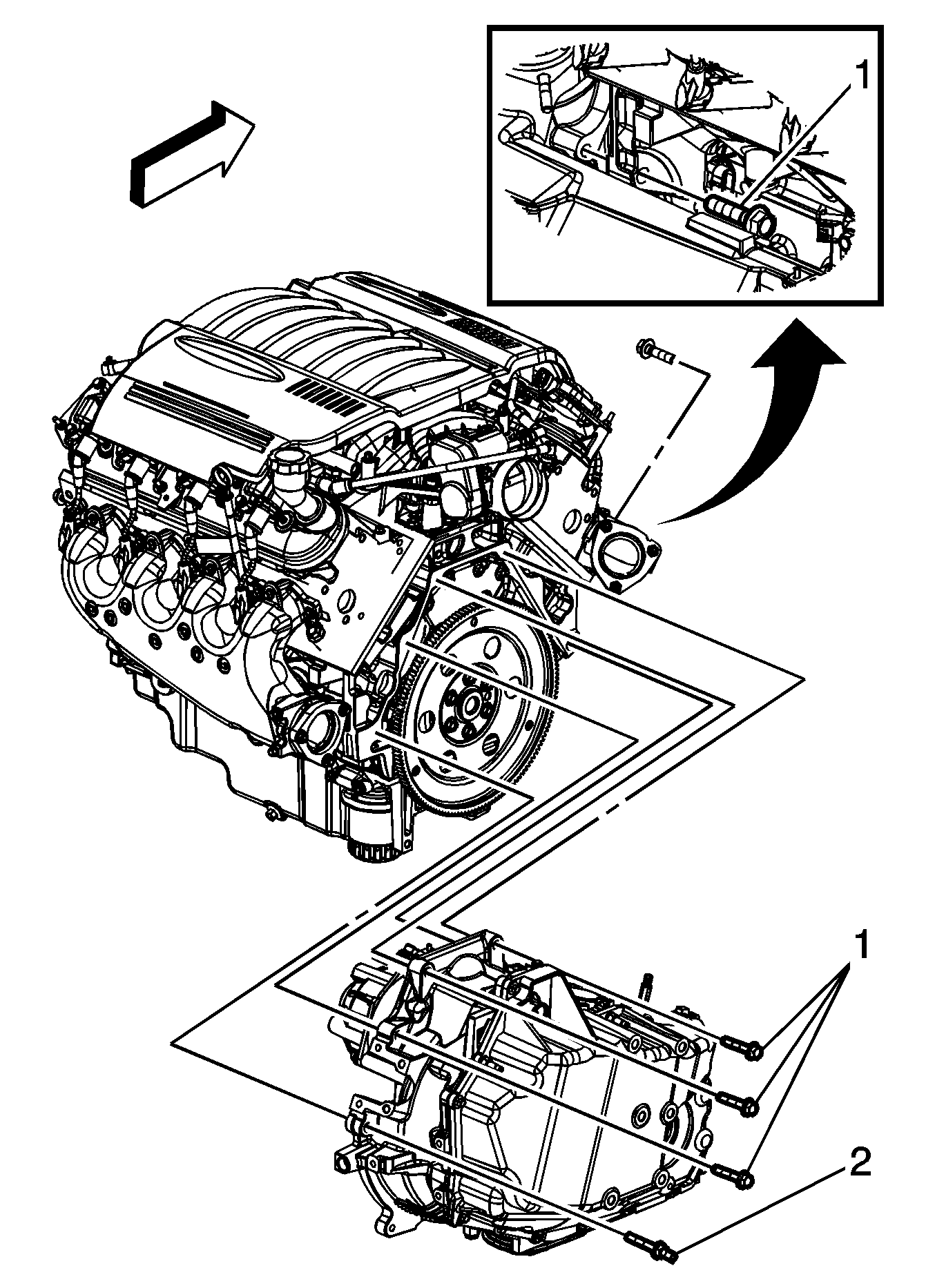
- Remove the transaxle to engine bolts (1) and stud (2).
- Separate the engine from the transaxle.
- Using a suitable engine lift, remove the engine from the frame.
- Install the engine onto a suitable engine stand.





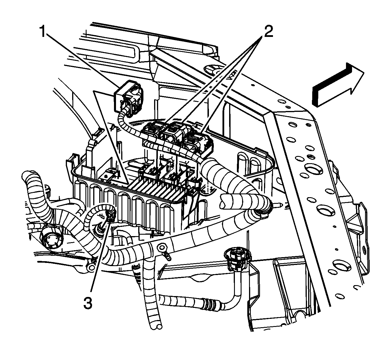
| • | Transmission control module (TCM) (1) |
| • | Engine control module (ECM) (2) |
| • | A/C pressure sensor (3) |





Installation Procedure
- Using a suitable engine lift, remove the engine from the engine stand.
- Position and install the engine to the frame and the transaxle.
- Install the transaxle to engine bolts (1) and stud (2).
- Install the rear engine mount to frame nuts.
- Install the front engine mount to frame nuts.
- Ensure that all hoses, wires, and pipes clear the vehicle during the installation process.
- With the aid of an assistant, raise the J 39580 and/or lower the vehicle to install the engine and frame to the vehicle.
- Install the engine frame rear bolts.
- Install the engine frame front bolts.
- Install radiator to front frame brackets.
- Lower the J 39580 , or raise the vehicle to preload the weight of the engine, frame, and front suspension.
- Remove the support from under the rear of the vehicle.
- Raise the vehicle enough to remove the J 39580 from under the engine, frame, and front suspension.
- Connect the exhaust system and connect the O2 sensor harness pigtail. Refer to Catalytic Converter Replacement .
- Install the flywheel bolts.
- Install the converter cover.
- Install the transaxle converter cover bolt/stud.
- Install the left and right wheel drive shafts into the transaxle. Refer to Wheel Drive Shaft Replacement .
- Install the battery cable retainers to the engine frame.
- Install the front air deflector. Refer to Radiator Air Lower Baffle and Deflector Replacement .
- Install the cable ground terminal (6) to the stud.
- Install the battery cable ground nut (1).
- Install the cable terminal (2) to the starter.
- Install the positive battery cable nut (3) to the starter.
- Connect the transaxle oil cooler lines to the transaxle. Refer to Transmission Fluid Cooler Hose/Pipe Quick-Connect Fitting Disconnection and Connection .
- Install the transaxle oil cooler line bracket bolt/stud.
- Install the power steering hose (2) to the inlet pipe.
- Tighten the power steering hose clamp at the inlet pipe.
- Connect the power steering pipe to the steering gear. Refer to Power Steering Pressure Pipe/Hose Replacement .
- Connect the power steering pipe to the frame clips.
- Lower the vehicle.
- Position and install the ball joint nuts. Refer to Lower Control Arm Ball Joint Replacement .
- Install the sway links to the stabilizer shaft. Refer to Stabilizer Shaft Link Replacement .
- Install the tie rod ends to the steering knuckles. Refer to Rack and Pinion Outer Tie Rod End Replacement .
- Connect the wheel speed sensor electrical connectors.
- Connect the wheel speed sensor wiring harness to the lower control arm.
- Install the heater inlet (2) and outlet (1) hoses to the heater inlet/outlet pipe.
- Using the J 38185 position the heater inlet and outlet hose clamps.
- Install the intermediate shaft to the steering gear.
- Install the intermediate shaft to steering gear bolt.
- Position the intermediate shaft lower boot.
- Route all branches of the engine wiring harness to their correct locations.
- Connect the engine harness electrical connector to the VSS.
- Install the VSS shield (2). Install the VSS shield nut (1) and bolt (3).
- Install the shift cable to the bracket.
- Connect the shift cable to the transaxle selector lever stud.
- Install the shift cable clip.
- Install the clip attaching the power steering gear harness to the bracket.
- Connect the engine harness electrical connector (1) to the CKP sensor harness.
- Connect the engine harness electrical connector (2) to the power steering gear harness.
- Connect the camshaft position sensor lead to the sensor.
- Connect the following electrical connectors:
- Install the air cleaner assembly. Refer to Air Cleaner Element Replacement .
- Connect the engine harness electrical connector to the EBCM.
- Connect the engine harness electrical connector to the ABS module.
- Install the engine harness connector to the bracket. Tighten the engine harness connector bolt (1).
- Position the fuse block. Tighten the 4 integral bolts (2) attaching the fuse block.
- Install the electrical center cover (1).
- Connect the fuel feed line (1) to the fuel rail. Refer to Metal Collar Quick Connect Fitting Service .
- Connect the EVAP line (2) to the purge solenoid. Refer to Plastic Collar Quick Connect Fitting Service .
- Remove the mechanic's wire holding the master cylinder. Position the master cylinder to the brake booster.
- Install the master cylinder nuts.
- Connect the brake pipe fittings (1, 2) to the ABS module.
- Connect the from brake pipe fittings (1, 2) to the master cylinder.
- Connect the brake fluid level switch electrical connector (3) to the master cylinder.
- Connect the engine harness electrical connectors (1, 2) to the I/P harness electrical connectors.
- Install the brake booster vacuum hose (1) to the intake manifold (2).
- Install the brake booster vacuum hose to the brake booster (3).
- Install the A/C compressor hose.
- Install the A/C compressor hose nut at the A/C condenser.
- Install the A/C compressor hose.
- Install the A/C compressor hose nut at the A/C receiver/dehydrator tube.
- Install the outlet hose to the radiator.
- Connect the outlet hose clips to the fan shroud.
- Using the J 38185 position the outlet hose clamp at the radiator.
- Install the inlet hose to the radiator.
- Using the J 38185 position the inlet hose clamp at the radiator.
- Install the front tires and wheels. Refer to Tire and Wheel Removal and Installation .
- Connect the negative battery cable. Refer to Battery Negative Cable Disconnection and Connection .
- Install the right fender diagonal brace. Refer to Front Fender Upper Diagonal Brace Replacement .
- Refill the engine with oil.
- Recharge the A/C system. Refer to Refrigerant Recovery and Recharging .
- Refill the cooling system. Refer to Cooling System Draining and Filling .
- Bleed the brake system. Refer to Hydraulic Brake System Bleeding .
- Check the transaxle fluid level, add fluid if necessary. Refer to Transmission Fluid Check .
- Install the engine sight shield. Refer to Upper Intake Manifold Sight Shield Replacement .
- Run the engine and inspect for leaks.

Notice: Refer to Fastener Notice in the Preface section.
Tighten
Tighten the bolts/stud to 75 N·m (55 lb ft).

Tighten
Tighten the nuts to 50 N·m (37 lb ft).

Tighten
Tighten the nuts to 50 N·m (37 lb ft).

Tighten
Tighten the bolts to 160 N·m (118 lb ft).

Tighten
Tighten the bolts to 145 N·m (107 lb ft).


Tighten
Tighten the bolts to 63 N·m (47 lb ft).

Tighten
Tighten the bolt/stud to 10 N·m (89 lb in).


Tighten
Tighten the nut to 30 N·m (22 lb ft).
Tighten
Tighten the nut to 10 N·m (89 lb in).

Tighten
Tighten the bolt/stud to 25 N·m (18 lb ft).

Tighten
Tighten the clamp to 6 N·m (53 lb in).


Tighten
Tighten the bolt to 48 N·m (35 lb ft).


Tighten
Tighten the bolt/nut to 25 N·m (18 lb ft).


| • | TCM (1) |
| • | ECM (2) |
| • | A/C pressure sensor (3) |


Tighten
Tighten the bolt to 10 N·m (89 lb in).

Tighten
Tighten the bolts to 10 N·m (89 lb in).


Tighten
Tighten the nuts to 33 N·m (24 lb ft).

Tighten
Tighten the fittings to 15 N·m (11 lb ft).

Tighten
Tighten the fittings to 30 N·m (22 lb ft).


Tighten
Tighten the nut to 16 N·m (12 lb ft).

Tighten
Tighten the nut to 16 N·m (12 lb ft).


