Tools Required
J 6627-A Tie Rod Puller
Removal Procedure
- Raise and support the vehicle. Refer to Lifting and Jacking the Vehicle in General Information.
- Measure and record the distance between the 2 lock nuts on the center adjuster.
- Use paint in order to mark the position of the 2 lock nuts on the center adjuster.
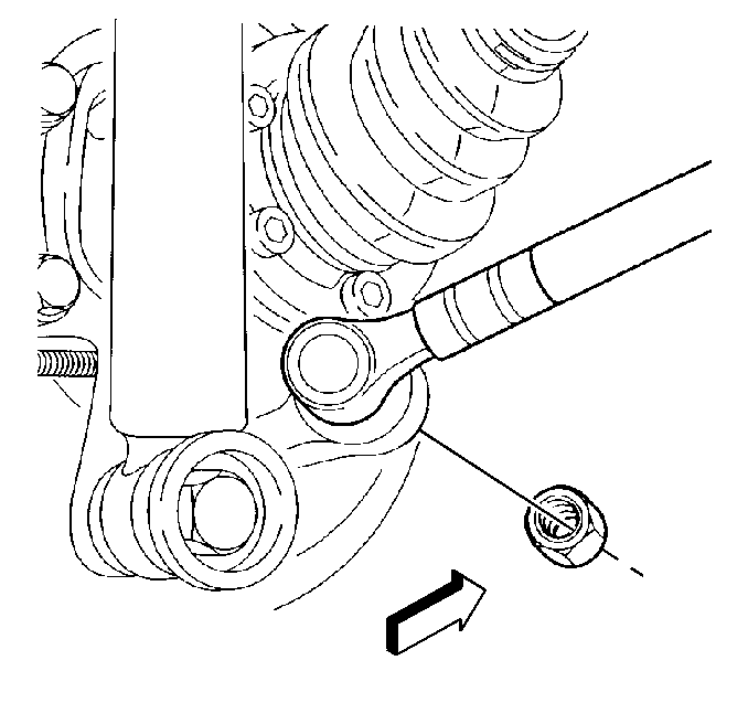
- Loosen the nut that retains the outer adjustment link to the control arm.
- Position the top of the nut with the top of the outer adjustment link stud.
- Use the J 6627-A , or equivalent, in order to separate the stud from the control arm.
- Remove and discard the nut.
- Remove the nut and the bolt that retain the inner adjustment link to the rear suspension support.
- Discard the nut.
- Remove the inner adjustment link from the rear suspension support.

Disassemble Procedure
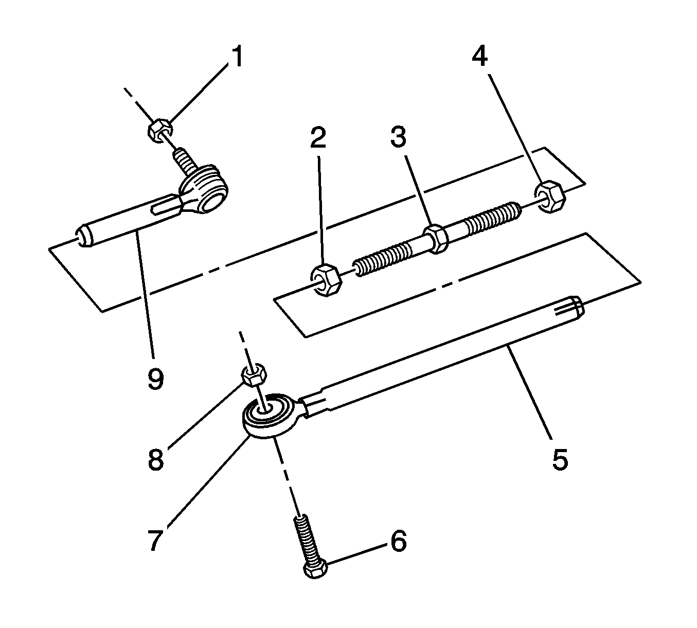
- Use a vise with soft jaws in order to hold the center adjuster (3).
- Loosen the inner lock nut.
- Remove the inner adjustment link from the center adjuster.
- Loosen the outer lock nut (4).
- Remove the outer adjustment link from the center adjuster.

Important: The following components have left-hand threads:
• The inner adjustment link (5) • The inner lock nut (2) • The corresponding end of the center adjuster
Important: Count the turns necessary for removal of the inner adjustment link.
Important: Count the turns necessary for removal of the outer adjustment link (9).
Assemble Procedure
- Thread the outer adjustment link (9) to the center adjuster (3) the same number of turns as for the removal.
- Align the match marks on the outer adjuster lock nut (4) and on the center adjuster.
- Thread the inner adjustment link (5) to the center adjuster the same number of turns as for the removal.
- Align the match marks on the inner adjuster lock nut (2) and on the center adjuster.
- Ensure the distance between the lock nuts is the same as during the removal.
- Remove the adjustment link from the vise.

Important: Do not tighten the nuts yet. The weight of the vehicle must be on the tire and wheel assemblies before tightening the suspension fasteners.
Installation Procedure
- Install the inner adjustment link to the rear suspension support.
- Install the NEW nut and the bolt in order to retain the inner adjustment link to the rear suspension support.
- Clean the stud on the outer adjustment link.
- Clean the hole in the control arm for the outer adjustment link stud.
- Install the outer adjustment link and a NEW nut to the control arm.
- Lower the vehicle.
- With the weight of the vehicle on the tire and wheel assemblies, bounce the rear of the vehicle several times in order to stabilize the rear suspension.
- Measure the wheel alignment. Refer to Wheel Alignment Measurement in Wheel Alignment.
- Use a wrench on the hexagonal crimped section of the outer adjustment link in order to hold the position of the ball joint.
- Adjust the rear toe to the specification and tighten the 2 lock nuts. Refer to Rear Toe Adjustment in Wheel Alignment.
- Tighten the nut and the bolt that retain the inner adjustment link to the rear suspension support.
- Tighten the nut that retains the outer adjustment link to the control arm.

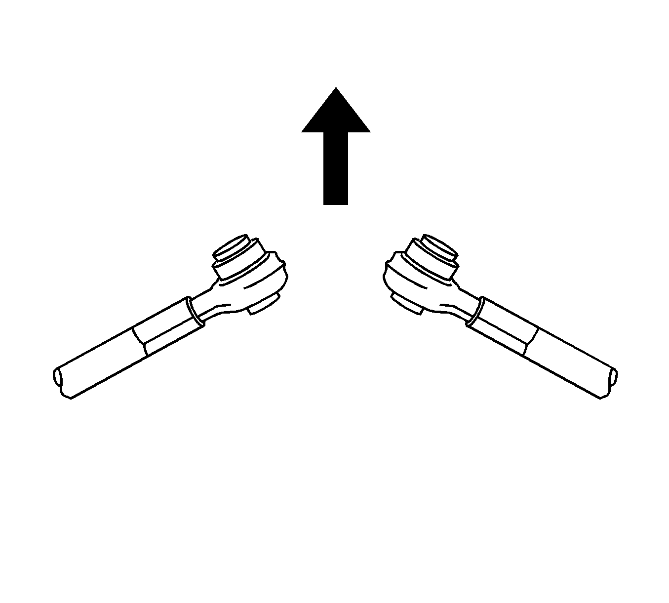
Important: The protruding side of the bushing must be toward the front of the vehicle.
Important: Do not tighten the nuts or the bolts. The weight of the vehicle must be on the tire and wheel assemblies before tightening the nuts and the bolts.

Notice: Refer to Fastener Notice in the Preface section.
Tighten
Tighten the nut and the bolt to 63 N·m (46 lb ft).
Tighten
Tighten the nut to 63 N·m (46 lb ft).
