Tools Required
| • | J 43032 Crankshaft
Rotation Socket |
| • | J 42042 Timing
Chain/Sprocket Holding Fixture |
Removal Procedure
- Remove the right camshaft cover. Refer to
Camshaft Cover Replacement - Right Side
.
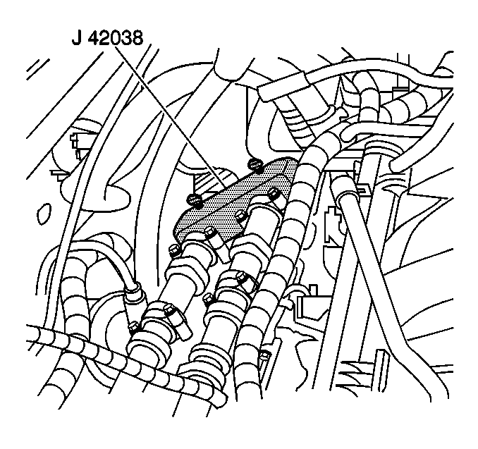
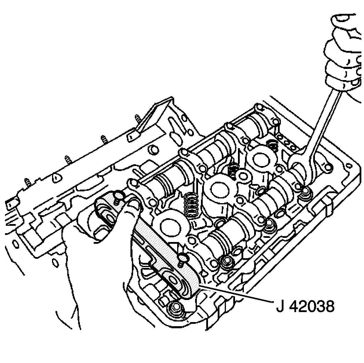
Important: You must install the J 42038
immediately after cam cover removal. The J 42038
prevents unexpected camshaft rotation
caused by valve spring pressure.
- Install the J 42038
on to the right camshafts.
When installed properly the J 42038
will be fully seated on the camshaft ends with the camshaft
flats parallel to the cam cover sealing surface.
- Remove the camshaft position sensor. Refer to
Camshaft Position Sensor Replacement
in Engine Controls-3.5L.
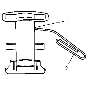
- Compress the secondary
timing chain tensioner with your hand.
- Lock the tensioner by inserting a piece of wire (2) into
the access hole in the side of the tensioner.
- Slowly release the pressure on the tensioner. The tensioner should
remain compressed.
- Remove the camshaft sprocket bolts.
- Install the J 42042
on to the right cylinder head.
- Evenly slide the secondary drive chain and camshaft sprockets
off the camshafts on to the J 42042
.
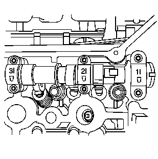
- Observe the markings on
the bearing caps. Each bearing cap is marked in order to identify its location.
The markings have the following meanings:
| • | The raised feature must always be oriented toward the outboard
of the engine. |
| • | The "I" indicates the intake camshaft. |
| • | The "E" indicates the exhaust camshaft. |
| • | The number indicates the journal position from the front of the
engine. |
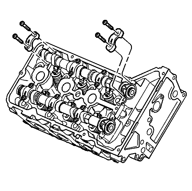
- Remove the camshaft bearing
cap retaining bolts.
- Remove the camshaft bearing caps. The cap closest to the front
of the engine is the thrust cap and must not be installed in another location.
- Remove the J 42038
from the right camshafts.
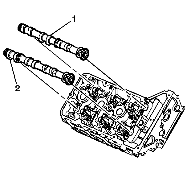
- Lift the camshaft (1 or 2)
out of the cylinder head.
- Clean and inspect the camshaft. Refer to
Camshaft Cleaning and Inspection
in Engine Mechanical-3.5L-Unit
Repair.
- Cover the camshaft with an oil soaked towel in order to prevent
corrosion.
Installation Procedure
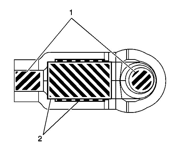
- Apply a liberal amount
of camshaft and lifter prelube GM P/N 12345501 or equivalent to the roller (2),
lash adjuster and valve tip areas (1) of the camshaft followers.
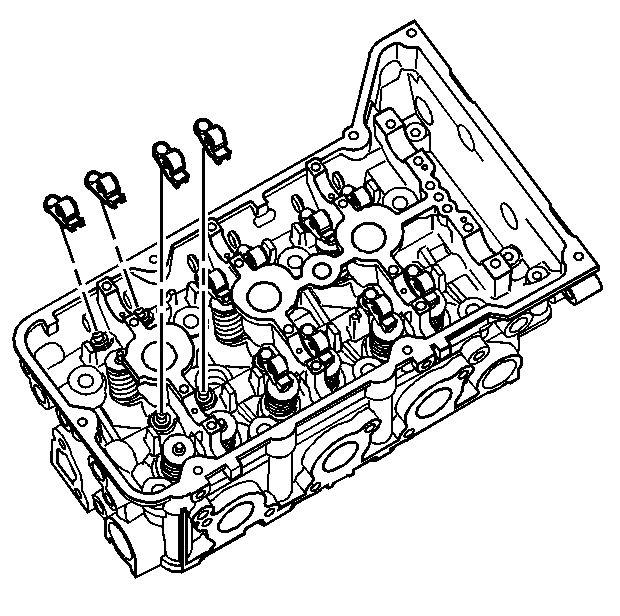
Important: The follower must be positioned squarely on the valve tip so that the
full width of the roller will completely contact the camshaft lobe. If the
followers are being reused you must put them back in their original location.
- Place the camshaft followers in position on the valve tip and lifter.
The rounded head end of the follower goes on the lash adjuster while the flat
end goes on the valve tip.
- Clean the camshaft journals and carriers with a clean, lint-free
cloth.
Important: Use the J 43032
in order to make sure that the crankshaft is in the TDC position.
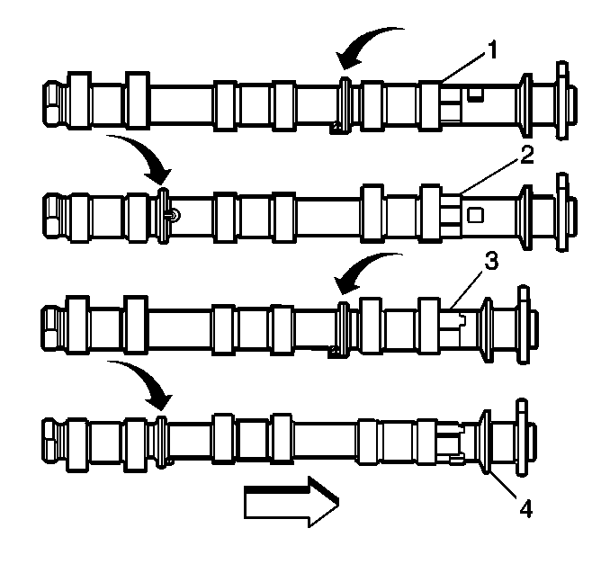
- Select the proper camshaft for the particular installation location.
The left cylinder head camshafts (1, 2) are longer than those
for the right cylinder head (3, 4). However, both sets of
camshafts share the same placement of identification rings. The ring placement
is defined as follows:
| 4.1. | The identification ring for the intake camshafts (1, 3)
is located between the first and second sets of lobes. |
| 4.2. | The identification ring for the exhaust camshafts (2, 4)
is located between the second and third sets of lobes. |

- Apply a liberal amount
of camshaft and lifter prelube GM P/N 12345501 or equivalent to the camshaft
journals and the cylinder head camshaft carriers.
- Place the intake (1) and exhaust (2) camshafts in
position in the cylinder head.
- Position the camshaft lobes in a neutral position with the front
notch for the camshaft sprocket drive pins near the top of their rotation
and the rear flats of the camshaft near the installation position of the J 42038
.

- Observe the markings on
the bearing caps. Each bearing cap is marked in order to identify its location.
The markings have the following meanings:
| • | The raised feature must always be oriented toward the outboard
of the engine. |
| • | The "I" indicates the intake camshaft. |
| • | The "E" indicates the exhaust camshaft. |
| • | The number indicates the journal position from the front of the
engine. |

- Install the camshaft bearing
thrust caps in the first journal of each camshaft. The thrust caps are wider
than the others and have machined undercuts not present on the other caps.
Make sure the orientation marking is closest to the engine valley.
- Install the remaining bearing caps with their orientation mark
closest to the engine valley.
- Hand start all the camshaft bearing cap bolts.
Notice: Use the correct fastener in the correct location. Replacement fasteners
must be the correct part number for that application. Fasteners requiring
replacement or fasteners requiring the use of thread locking compound or sealant
are identified in the service procedure. Do not use paints, lubricants, or
corrosion inhibitors on fasteners or fastener joint surfaces unless specified.
These coatings affect fastener torque and joint clamping force and may damage
the fastener. Use the correct tightening sequence and specifications when
installing fasteners in order to avoid damage to parts and systems.
- Tighten the camshaft
bearing caps.
Tighten
- Tighten the camshaft bearing cap bolts to 8 N·m (71 lb in).
- Use theJ 36660-A
in order to tighten the camshaft bearing cap bolts an additional 22 degrees.
Important: Do not rotate the camshaft more than 10 degrees.
- Using the hex cast into the camshaft, rotate the camshaft so the rear
camshaft flat is facing the cylinder head.
- Install the J 42038
at the rear of the cylinder head.

Important: The camshafts must be locked in place using the J 42038
before installation of the secondary
timing chain.
- Make sure the locking tool is fully seated and locked onto the camshafts.
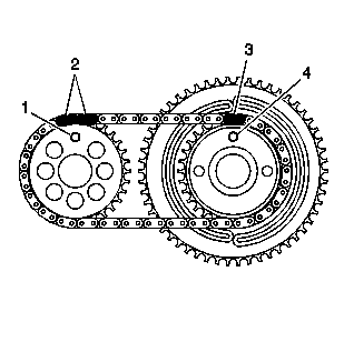
- Slide the intake and exhaust
camshaft sprockets off of the J 42042
and onto their respective camshafts and align the drive pins (1)
in the camshafts.
- Remove the J 42042
from the right cylinder head.
- Install the intake camshaft sprocket bolt and exhaust camshaft
sprocket bolt.
Tighten
- Tighten the camshaft sprocket bolts to 25 N·m (18 lb ft).
- Use theJ 36660-A
in order to tighten the camshaft bearing cap bolts an additional 45 degrees.
- Remove the locking wire from the secondary timing chain tensioner
allowing the tensioner shoes to expand and apply pressure to the timing chain.
- Install the camshaft position sensor. Refer to
Camshaft Position Sensor Replacement
in Engine Controls-3.5L.

- Remove the J 42038
from the right camshafts.
- Install the right camshaft cover. Refer to
Camshaft Cover Replacement - Right Side
.


