Removal Procedure
- Raise and support the vehicle. Refer to Lifting and Jacking the Vehicle in General Information.
- Drain the engine coolant from the cooling system. Refer to Cooling System Draining and Filling in Engine Cooling.
- Drain the engine oil. Refer to Engine Oil and Oil Filter Replacement .
- Remove the front tires and wheels. Refer to Tire and Wheel Removal and Installation in Tires and Wheels.
- Remove the lower air deflector. Refer to Radiator Air Baffle Assemblies and Deflectors in Engine Cooling.
- Lower the vehicle.
- Remove the fuel injector sight shield. Refer to Fuel Injector Sight Shield Replacement .
- Remove the left diagonal brace. Refer to Front End Sheet Metal Diagonal Brace Replacement in Body Front End.
- Remove the air cleaner assembly. Refer to Air Cleaner Assembly Replacement in Engine Controls-3.5L.
- Remove the radiator inlet hose. Refer to Radiator Inlet Hose Replacement in Engine Cooling.
- Remove the generator. Refer to Generator Replacement in Engine Electrical.
- Relieve the fuel pressure. Refer to Fuel Pressure Relief in Engine Controls-3.5L.
- Disconnect the fuel lines from the fuel rail. Position the fuel lines aside. Refer to one of the following procedures:
- Disconnect the fuel vapor line.
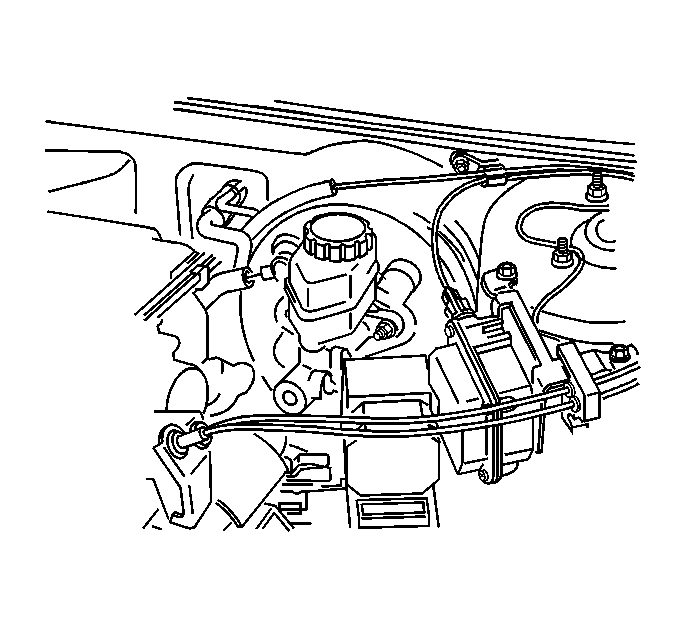
- Disconnect the throttle and cruise cables with the mounting bracket from the throttle body. Refer to the following procedures:
- Disconnect the automatic range selector cable from the park/neutral position (PNP) switch. Refer to Range Selector Lever Cable Replacement in Automatic Transaxle-4T65-E.
- Remove the vacuum brake booster hose from the booster.
- Remove the transaxle oil cooler lines from the radiator. Refer to Automatic Transmission Oil Cooler Hose Replacement in Automatic Transaxle-4T65-E.
- Remove the heater hoses from the engine. Refer to Heater Hoses Replacement in Heating, Ventilation and Air Conditioning.
- If the vehicle is equipped, remove the right side A.I.R. control valve. Refer to Secondary Air Injection Shutoff Valve Replacement - Bank 1 in Engine Controls-3.5L.
- Disconnect the upper engine electrical connectors, including grounds.
- Raise the vehicle.
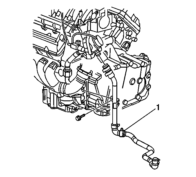
- If the vehicle is equipped, remove the lower A.I.R. hose from the elbow (1). Discard the clamp.
- Disconnect the lower electrical connectors, including grounds and the harness retainers.
- If the vehicle is equipped, disconnect the fog lamp electrical connectors.
- Remove the torque converter cover. Refer to Torque Converter Cover Replacement in Automatic Transaxle-4T65-E.
- Remove the starter motor Refer to Starter Motor Replacement in Engine Electrical.
- Scribe the torque converter to the flywheel in order to aid in installation.
- Remove the engine flywheel-to-torque converter bolts. Refer to Flywheel to Torque Converter Bolt Replacement in Automatic Transaxle-4T65-E.
- Remove the inner fender engine splash shields. Refer to Engine Splash Shield Replacement in Body Front End.
- Remove the A/C compressor mounting bolts and nuts. DO NOT discharge the system. Secure the compressor. Refer to Air Conditioning Compressor Replacement in Heating, Ventilation and Air Conditioning.
- Remove the 3 way catalytic converter pipe from the right (rear) exhaust manifold. Refer to Catalytic Converter Replacement in Engine Exhaust.
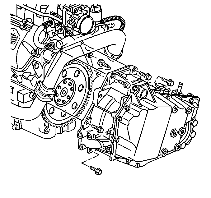
- Remove the lower transaxle-to-engine bolts.
- Disconnect the electrical connectors from the wheel speed sensors and unclip the harnesses from the lower control arms.
- Remove the wheel drive axles from the steering knuckles. Refer to Wheel Drive Shaft Replacement in Wheel Drive Shafts.
- Remove the pinch bolt at the intermediate steering shaft. Refer to Intermediate Steering Shaft Replacement in Steering Wheel and Column - Tilt.
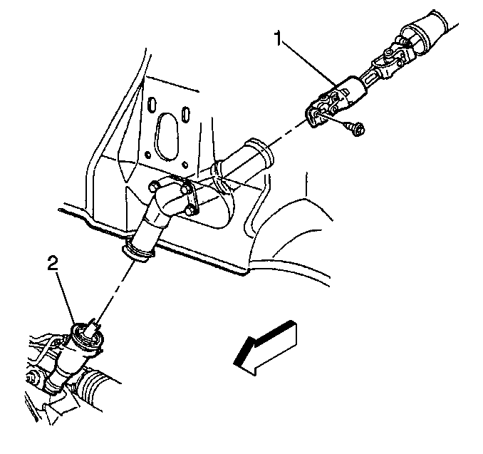
- Disconnect the intermediate shaft (1) from the steering gear (2). Refer to Intermediate Steering Shaft Replacement in Steering Wheel and Column - Tilt.
- Lower the vehicle.
- Reposition the upper and lower engine wiring harnesses.
- Raise the vehicle.
- Place the J 39580 under the engine/transaxle/frame.
- With an assistant, lower the vehicle to the frame table in order to support the engine/transaxle/frame.
- Remove the frame-to-body bolts. Refer to Frame Replacement in Frame and Underbody.
- Raise the vehicle.
- Remove the frame table with the engine/transaxle/frame from under the vehicle.
- Remove the power steering pump from the engine and lay aside. Refer to Power Steering Pump Replacement in Power Steering System.
- If the vehicle is equipped, remove the secondary air injection check valve/pipe. Refer to Secondary Air Injection Shutoff Valve Replacement - Bank 2 in Engine Controls-3.5L.
- Remove the oil level indicator tube. Refer to Oil Level Indicator and Tube Replacement
- Remove the exhaust manifolds and crossover pipe. Refer to the following procedures:
- Install the engine lifting device to the engine.
- Remove the engine mount bracket-to-engine bolts. Refer to Engine Front Mount Bracket Replacement in Engine Mechanical-3.5L.
- Remove the transaxle brace. Refer to Transmission Brace Replacement in Automatic Transaxle-4T65-E.
- Remove the upper transmission-to-engine bolts.
- Remove the engine from the transaxle/frame.
- Remove the engine flywheel. Refer to Engine Flywheel Replacement in Engine Mechanical-3.5L.
| • | Metal Collar Quick Connect Fitting Service in Engine Controls-3.5L |
| • | Plastic Collar Quick Connect Fitting Service in Engine Controls-3.5L |
| • | Accelerator Control Cable Replacement in Engine Controls-3.5L |
| • | Accelerator Control Cable Bracket Replacement in Engine Controls-3.5L |
Caution: To avoid any vehicle damage, serious personal injury or death when major components are removed from the vehicle and the vehicle is supported by a hoist, support the vehicle with jack stands at the opposite end from which the components are being removed and strap the vehicle to the hoist.
Caution: Failure to disconnect the intermediate shaft from the rack and pinion stub shaft can result in damage to the steering gear and/or damage to the intermediate shaft. This damage may cause loss of steering control which could result in personal injury.
Important: Carefully adjust the A/C compressor as the vehicle is raised.
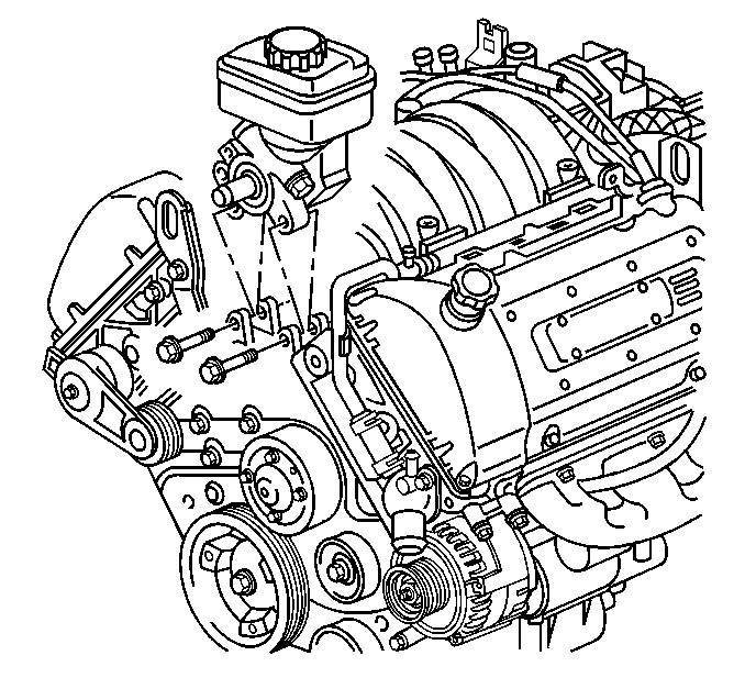

Installation Procedure
- Install the engine flywheel. Refer to Engine Flywheel Replacement in Engine Mechanical-3.5L.
- Install the engine to the transaxle/frame.
- Install the upper transmission-to-engine bolts.
- Install the transaxle brace. Refer to Transmission Brace Replacement in Automatic Transaxle-4T65-E.
- Install the engine mount bracket-to-engine bolts. Refer to Engine Front Mount Bracket Replacement .
- Remove the engine lifting device from the engine.
- Install the crossover pipe and the exhaust manifolds. Refer to the following procedures:
- Install the oil level indicator tube. Refer to Oil Level Indicator and Tube Replacement .
- If the vehicle is equipped, install the secondary air injection check valve/pipe. Refer to Secondary Air Injection Shutoff Valve Replacement - Bank 2 in Engine Controls-3.5L.
- Install the power steering pump to the engine. Refer to Power Steering Pump Replacement in Power Steering System.
- Install the frame table with the engine/transaxle/frame under the vehicle.
- Lower the vehicle.
- Install the frame-to-body bolts. Refer to Frame Replacement in Frame and Underbody.
- Install the pinch bolt at the intermediate steering shaft. Refer to Intermediate Steering Shaft Replacement in Steering Wheel and Column - Tilt.
- Raise the vehicle.
- Remove the J 39580 from under the vehicle.
- Lower the vehicle.
- Reposition the upper and lower engine wiring harnesses to the engine.
- Raise the vehicle.
- Install the wheel drive axles to the steering knuckles. Refer to Wheel Drive Shaft Replacement in Wheel Drive Shafts.
- Connect the electrical connectors to the wheel speed sensors and clip the harnesses to the lower control arms.
- Install the lower transaxle-to-engine bolts.
- Install the 3 way catalytic converter pipe to the right (rear) exhaust manifold. Refer to Catalytic Converter Replacement in Engine Exhaust.
- Install the A/C compressor. Refer to Air Conditioning Compressor Replacement in Heating, Ventilation and Air Conditioning.
- Install the inner fender engine splash shields. Refer to Engine Splash Shield Replacement in Body Front End.
- Install the engine flywheel-to-torque converter bolts. Refer to Flywheel to Torque Converter Bolt Replacement in Automatic Transaxle-4T65-E.
- Install the starter motor. Refer to Starter Motor Replacement in Engine Electrical.
- Install the torque converter cover. Refer to Torque Converter Cover Replacement in Automatic Transaxle-4T65-E.
- If the vehicle is equipped, connect the fog lamp electrical connectors.
- Connect the lower electrical connectors including grounds and the harness retainers.
- If the vehicle is equipped, install the lower A.I.R. hose to the elbow (1). Replace the clamp.
- Install the lower air deflector. Refer to Radiator Air Baffle Assemblies and Deflectors in Engine Cooling.
- Install the front tires and wheels. Refer to Tire and Wheel Removal and Installation in Tires and Wheels.
- Remove the vehicle to hoist support.
- Lower the vehicle.
- Connect the upper engine electrical connectors and grounds.
- Install the harnesses to the clips.
- If the vehicle is equipped, install the right A.I.R. control valve. Refer to Secondary Air Injection Shutoff Valve Replacement - Bank 1 in Engine Control-3.5L.
- Install the heater hoses to the engine. Refer to Heater Hoses Replacement in Heating, Ventilation and Air Conditioning.
- Install the transaxle oil cooler lines to the radiator. Refer to Automatic Transmission Oil Cooler Hose Replacement in Automatic Transaxle-4T65-E.
- Install the A/C vacuum hose to the engine.
- Install the vacuum brake booster hose to the booster.
- Connect the automatic range selector cable to the PNP switch. Refer to Range Selector Lever Cable Replacement in Automatic Transaxle-4T65-E.
- Connect the throttle and cruise cables with the mounting bracket to the throttle body. Refer to the following procedures:
- Connect the fuel vapor line.
- Connect the fuel lines to the fuel rail. Refer to one of the following procedures:
- Install the generator. Refer to Generator Replacement in Engine Electrical.
- Install the radiator inlet hose. Refer to Radiator Inlet Hose Replacement in Engine Cooling.
- Install the air cleaner assembly. Refer to Air Cleaner Assembly Replacement in Engine Controls-3.5L.
- Install the left diagonal brace. Refer to Front End Sheet Metal Diagonal Brace Replacement in Body Front End.
- Install the fuel injector sight shield. Refer to Fuel Injector Sight Shield Replacement .
- Fill the crankcase with engine oil. Refer to Engine Oil and Oil Filter Replacement .
- Fill the engine cooling system with engine coolant. Refer to Cooling System Draining and Filling in Engine Cooling.
- Perform the steering angle sensor centering procedure. Refer to Steering Angle Sensor Centering in Antilock Brake System.
- Perform the crankshaft position (CKP) sensor relearn. Refer to Crankshaft Position System Variation Learn in Engine Controls-3.5L.

Notice: Use the correct fastener in the correct location. Replacement fasteners must be the correct part number for that application. Fasteners requiring replacement or fasteners requiring the use of thread locking compound or sealant are identified in the service procedure. Do not use paints, lubricants, or corrosion inhibitors on fasteners or fastener joint surfaces unless specified. These coatings affect fastener torque and joint clamping force and may damage the fastener. Use the correct tightening sequence and specifications when installing fasteners in order to avoid damage to parts and systems.
Important: The transaxle-to-engine bolts must be returned to their original position. The bolt install in position (5) is 2 mm (0.078 in) shorter that the other transaxle-to-engine bolts and requires the use of GM P/N 12345382 thread sealant.
Tighten
Tighten the upper transmission-to-engine bolts to 75 N·m
(55 lb ft).
Caution: When installing the intermediate shaft make sure that the shaft is seated prior to pinch bolt installation. If the pinch bolt is inserted into the coupling before shaft installation, the two mating shafts may disengage. Disengagement of the two mating shafts will cause loss of steering control which could result in personal injury.
Important: Carefully adjust the A/C compressor as the vehicle is lowered.

Tighten
Tighten the lower transaxle-to-engine bolts to 75 N·m (55 lb ft).


| • | Accelerator Control Cable Replacement in Engine Controls-3.5L |
| • | Accelerator Control Cable Bracket Replacement in Engine Controls-3.5L |
| • | Metal Collar Quick Connect Fitting Service in Engine Controls-3.5L |
| • | Plastic Collar Quick Connect Fitting Service in Engine Controls-3.5L |
