For 1990-2009 cars only
Tools Required
| • | J 8001 Dial Indicator Set |
| • | J 26900-13 Magnetic Base |
- Raise and support the vehicle. Refer to Lifting and Jacking the Vehicle in General Information.
- Remove the tire and wheel assembly. Refer to Tire and Wheel Removal and Installation in Tires and Wheels.
- Remove the caliper. Refer to Brake Caliper Replacement .
- Install all the wheel nuts in order to retain the rotor.
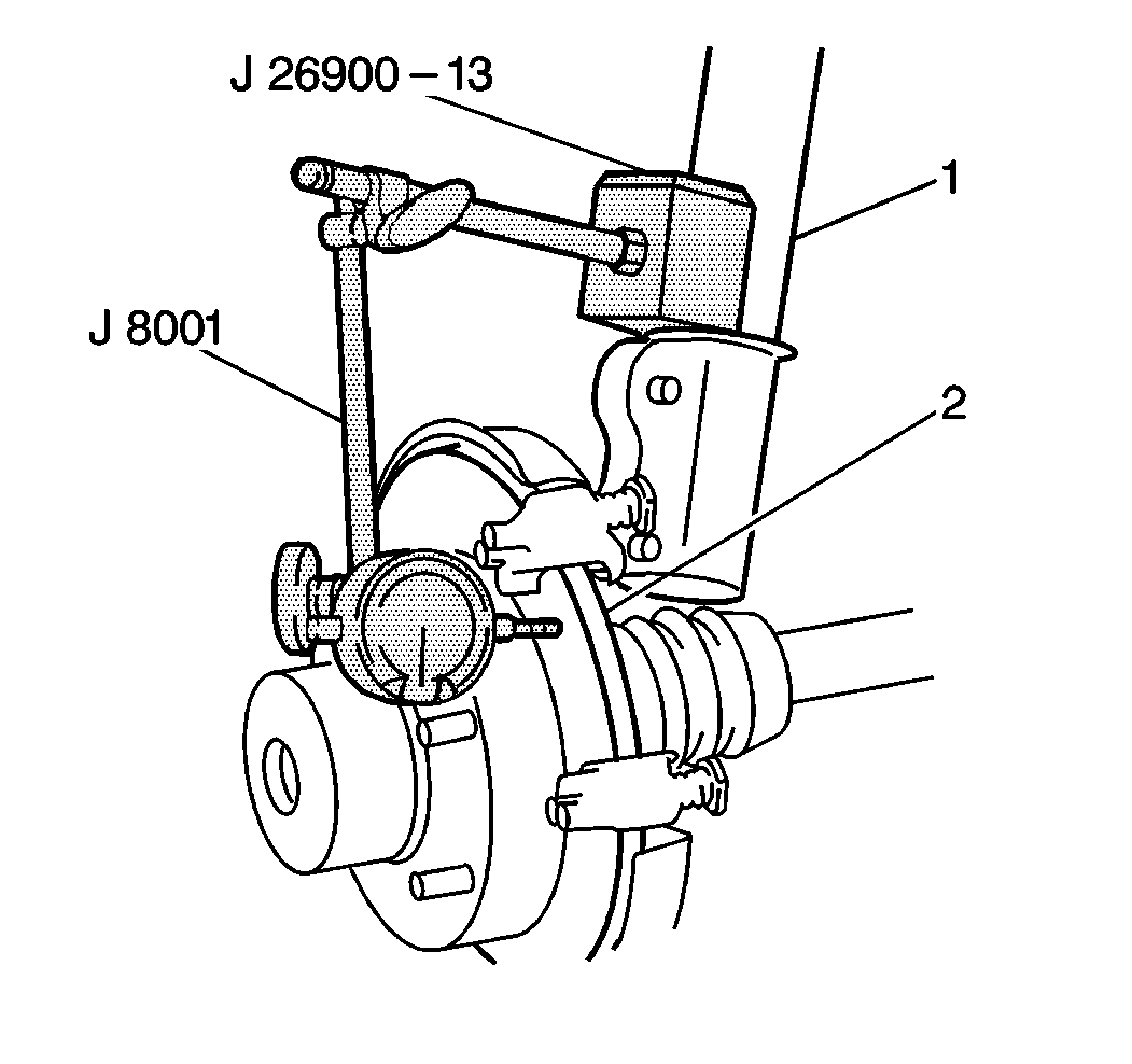
- Fasten a J 26900-13 and a J 8001 to the strut (1) so that the indicator button contacts the brake rotor (2) 25 mm (0.98 in) from the rotor edge.
- Zero the J 8001 .
- Move the rotor one complete revolution and observe the total indicated runout.
- If the lateral runout exceeds specifications, clean the wheel hub and rotor mating surfaces, and measure the lateral runout again.
- If the lateral runout still exceeds specifications, index the rotor on the hub one or two bolt positions from the original position.
- If the lateral runout cannot be corrected by indexing the rotor, inspect the hub and bearing assembly for runout. Refer to Tire and Wheel Vibration in Vibration Diagnosis.
- Inspect the hub and bearing assembly for looseness. Refer to Wheel Bearings Diagnosis in Suspension General Diagnosis.
- If the hub and bearing assembly are within specifications, measure the depth of the scoring on the rotor. Refer to Brake Rotor Tolerance .
- Refinish or replace any rotor that does not meet the lateral runout specification. Refer to Brake Rotor Refinishing or to Brake Rotor Replacement .

The maximum rotor lateral runout is 0.15 mm (0.006 in).
