Removal Procedure
-
Important: This vehicle uses a sequential multiport fuel injected engine. Fuel injector connectors must be positioned onto their appropriate fuel injector, otherwise, engine performance and exhaust emissions may be seriously affected.
Fuel injector connectors are numbered to match their correct fuel injector for that cylinder. Refer to Section 8A-20 for the correct fuel injector connector wire color to fuel injector for each cylinder, if the fuel injector connector numbers cannot be identified. - Disconnect the negative battery cable. Refer to
Caution: Unless directed otherwise, the ignition and start switch must be in the OFF or LOCK position, and all electrical loads must be OFF before servicing any electrical component. Disconnect the negative battery cable to prevent an electrical spark should a tool or equipment come in contact with an exposed electrical terminal. Failure to follow these precautions may result in personal injury and/or damage to the vehicle or its components.
in General Information. - Recover the R134a refrigerant. Refer to Refrigerent Recovery and Recycling , Adding Oil, Evacuating and Recharging Procedures in Heating and Air Conditioning.
- Drain the coolant. Refer to Draining and Refilling the Cooling System in Cooling and Radiator.
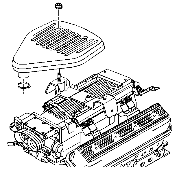
- Remove the air cleaner resonator bracket nuts.
- Remove the air cleaner resonator.
- Remove the air intake duct.
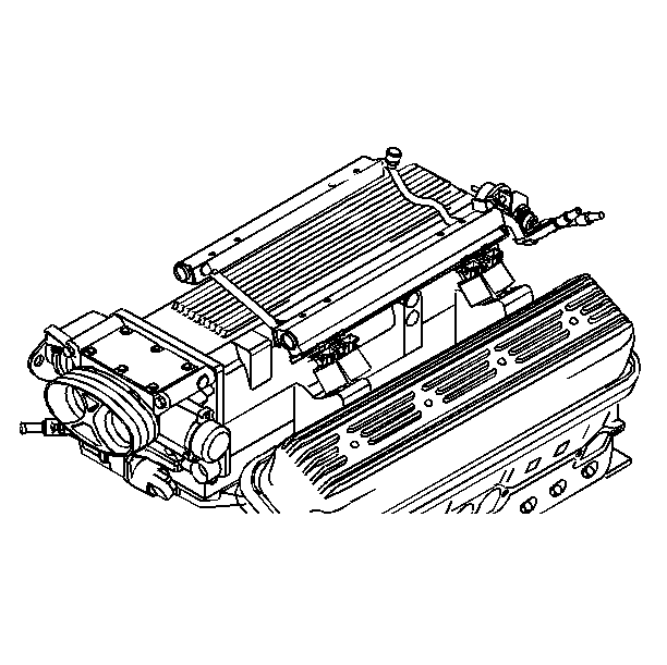
- Remove the fuel lines from the fuel rail. Refer to Fuel Hose and Pipes in Engine Controls.
- Remove the radiator fan upper shroud, if equipped with the mechanical fan. Refer to Radiator Fan Upper and Lower Shrouds in Cooling and Radiator.
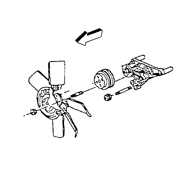
- Remove the fan blade clutch nuts and fan blade with clutch attached, if equipped with the mechanical fan.
- Remove the fan pulley, if equipped with the mechanical fan.
- Remove the heater hose at the water pump and bracket. Refer to Water Pump Replacement .
- Remove the accelerator control cable at the throttle body.
- Remove the radiator inlet and outlet hoses from the water pump and the engine.
- Remove the coolant hose at the throttle body.
- Raise the vehicle.
- Suitably support the vehicle. Refer to General Vehicle Lifting and Jacking in General Information.
- Remove the engine oil filter adapter hoses, if equipped. Refer to Oil Filter Adapter Replacement .
- Drain the engine oil.
- Remove the warm up the three-way catalytic converters and the gaskets from the exhaust manifolds. Refer to Warmup of the Three Way Catalytic Converter Replacement in Exhaust System.
- Remove the converter cover bolts and the converter cover. Refer to Transmission Replacement in Automatic Transmission On-Vehicle Service.
- Remove the converter bolts.
- Remove the serpentine drive belt. Refer to Drive Belt Replacement .
- Remove the air conditioning compressor and the condenser hose from the compressor. Refer to Air Conditioning Compressor and Condenser Hose in Heating and Air Conditioning.
- Remove the transmission fluid cooler lines from the engine clips.
- Remove the radiator fan lower shroud, if equipped with the mechanical fan. Refer to Radiator Fan Upper and Lower Shrouds in Cooling and Radiator.
- Remove the electric engine cooling fans. Refer to Engine Coolant Fan in Cooling and Radiator.
- Remove the electrical connections from the starter motor.
- Remove the electrical connectors from the knock sensor and oxygen sensors
- Remove the electrical connectors from the engine oil level switch and fuel pump switch/engine oil pressure gage sensors.
- Lower the vehicle.
- Remove the power steering inlet and outlet hoses at the pump.
- Remove the brake booster vacuum hose.
- Remove the generator wiring from the generator.
- Remove the engine wiring harness connectors and ground straps.
- Reposition the wiring harness.
- Raise the vehicle.
- Suitably support the vehicle. Refer to General Vehicle Lifting and Jacking in General Information.
- Remove the transmission to engine bolts.
- Remove the transmission filler tube bolt at the rear of the right side cylinder head.
- Remove the engine mount through bolts. Refer to Engine Mount Replacement .
- Lower the vehicle.
- Remove the engine wiring harness support at the left front corner of the intake manifold.
- Remove the engine from the vehicle.

| 6.1. | Loosen the clamp at the air intake duct and slide the resonator off the studs. |

| 24.1. | Plug the open ends of the lines and fittings. |
| 32.1. | In order to prevent excessive spillage, siphon the fluid from the reservoir. |
| 44.1. | Install the engine lifting device to the boss at the left front corner of the intake manifold, using a 3/8-16 NC standard thread bolt. Use a bolt long enough to thread into the intake manifold at least 25 mm (1 in). |
| 44.2. | Install the other end of the lifting device to the fourth bolt position on the right side of the intake manifold. Use a 3/8 -16 NC bolt long enough to thread into the cylinder head at least 25 mm (1 in). |
| Important: Clean and Inspect the Engine Block. Refer to Engine Block Clean and Inspect . |
Installation Procedure
- Install the engine to the vehicle.
- Install the engine wiring harness support at the left front corner of the intake manifold.
- Raise the vehicle.
- Suitably support the vehicle. Refer to General Vehicle Lifting and Jacking in General Information.
- Install the engine mount through bolts. Refer to Engine Mount Replacement .
- Install the transmission filler tube bolt at the rear of the right side of the cylinder head.
- Install the transmission-to-engine bolts.
- Lower the vehicle.
- Install the engine wiring harness, connectors and ground straps.
- Install the generator. Refer to Generator Replacement in Charging System.
- Install the generator wiring to the generator.
- Connect the brake booster vacuum hose.
- Install the power steering inlet and outlet hoses at the pump.
- Raise the vehicle.
- Suitably support the vehicle. Refer to General Vehicle Lifting and Jacking in General Information.
- Install the electrical connectors from the engine oil level switch and fuel pump switch/engine oil pressure gage sensors.
- Install the electrical connectors from the knock sensor and oxygen sensors
- Install the electrical connections to the starter motor.
- Install the electric engine cooling fans. Refer to Engine Coolant Fans in Cooling and Radiator.
- Install the radiator fan lower shroud, if removed. Refer to Radiator Fan Upper and Lower Shrouds in Cooling and Radiator.
- Install the transmission fluid cooler lines from the engine clips.
- Install the air conditioning compressor and the condenser hose from the compressor. Refer to Air Conditioning Compressor and Condenser Hose in Heating and Air Conditioning.
- Install the serpentine drive belt. Refer to Drive Belt Replacement .
- Install the torque converter bolts.
- Install the converter cover and the converter cover bolts. Refer to Transmission Removal and Installation in Automatic Transmission on Vehicle Service.
- Warm up the three-way catalytic converters and the gaskets from the exhaust manifolds. Refer to Warmup of the Three Way Catalytic Converter in Exhaust System.
- Install the engine oil filter adapter hoses, if equipped. Refer to Engine Oil Filter Adapter and Hoses in Engine on Vehicle Service.
- Lower the vehicle
- Install the coolant hose at the throttle body.
- Install the radiator inlet and outlet hoses to the water pump and the engine. Refer to Radiator Inlet and Outlet Hoses in Cooling and Radiator.
- Install the accelerator control cable to the throttle body.
- Install the heater hose at the water pump and bracket. Refer to Heater Hose and Water Pump Replacement in Engine Cooling.
- Install the fan pulley, if removed.
- Install the fan blade with clutch attached and the clutch nuts, if removed.
- Install the radiator fan upper shroud, if equipped with the mechanical fan. Refer to Radiator Fan Upper and Lower Shrouds in Cooling and Radiator.
- Install the fuel lines to the fuel rail. Refer to Fuel Hose and Pipes in Engine Controls.
- Install the air intake duct.
- Install the air cleaner resonator.
- Install the air cleaner resonator bracket nuts.
- Install the negative battery cable.
- Refill the engine with oil.
- Refill and bleed the cooling system. Refer to Bleeding the Cooling System in Cooling and Radiator.
- Refill and bleed the power steering system. Refer to Power Steering Fluid Replacement in Power Steering Gear and Pump On-Vehicle Service.
- Charge the air conditioning system with R134a refrigerant. Leak check the air conditioning hose fitting at the compressor. Refer to Refrigerant Recovery and Recycling, Adding Oil, Evacuating and Recharging Procedures in Heating and Air Conditioning.
- Reset the engine oil life monitor (unless the oil was not changed). Refer to Engine Oil life Monitor in Maintenance and Lubrication.
Tighten
Tighten the transmission filler tube bolts to 25 N·m (18 lb
ft).
Notice: Use the correct fastener in the correct location. Replacement fasteners must be the correct part number for that application. Fasteners requiring replacement or fasteners requiring the use of thread locking compound or sealant are identified in the service procedure. Do not use paints, lubricants, or corrosion inhibitors on fasteners or fastener joint surfaces unless specified. These coatings affect fastener torque and joint clamping force and may damage the fastener. Use the correct tightening sequence and specifications when installing fasteners in order to avoid damage to parts and systems.
Tighten
Tighten the transmission-to-engine bolts to 47 N·m (35 lb
ft).
| 9.1. | The fuel injector connectors must be connected to their appropriate fuel injector. Refer to Component Locator in Engine Controls. |
| 22.1. | Unplug the open ends of the lines and fittings. |
Tighten
Tighten the torque converter bolts to 63 N·m (46 lb ft).
Notice: Use the correct fastener in the correct location. Replacement fasteners must be the correct part number for that application. Fasteners requiring replacement or fasteners requiring the use of thread locking compound or sealant are identified in the service procedure. Do not use paints, lubricants, or corrosion inhibitors on fasteners or fastener joint surfaces unless specified. These coatings affect fastener torque and joint clamping force and may damage the fastener. Use the correct tightening sequence and specifications when installing fasteners in order to avoid damage to parts and systems.

Tighten
Tighten the fan blade clutch nuts to 26N·m (19 lb ft).


| 38.1. | Slide the resonator over the studs and tighten the clamp slightly. |
Tighten
Tighten the air cleaner resonator bracket nuts to 10 N·m
(89 lb ft ).
