Cylinder Head Replacement Left
Removal Procedure
- Disconnect the battery ground (negative) cable. Refer to
Caution: Unless directed otherwise, the ignition and start switch must be in the OFF or LOCK position, and all electrical loads must be OFF before servicing any electrical component. Disconnect the negative battery cable to prevent an electrical spark should a tool or equipment come in contact with an exposed electrical terminal. Failure to follow these precautions may result in personal injury and/or damage to the vehicle or its components.
in General Information. - Drain the coolant. Refer to Cooling and Radiator.
- Drain the engine oil.
- Remove the fuel injector sight shield (VIN K). Refer to Fuel Injector Sight Shield Replacement .
- Remove the fuel injector sight shield (VIN 1). Refer to Fuel Injector Sight Shield Replacement .
- Remove the air cleaner duct. Refer to Engine Controls.
- Remove the right engine mount strut bracket. Refer to Engine Mount Strut Bracket Replacement .
- Remove the lower intake manifold (VIN K). Refer to Intake Manifold Replacement .
- Remove the lower intake manifold (VIN 1). Refer to Intake Manifold Replacement .
- Remove the left (front) exhaust manifold. Refer to Exhaust Manifold Replacement
- Remove the left (front) rocker arms and push rods. Refer to Valve Rocker Arm and Push Rod Replacement .
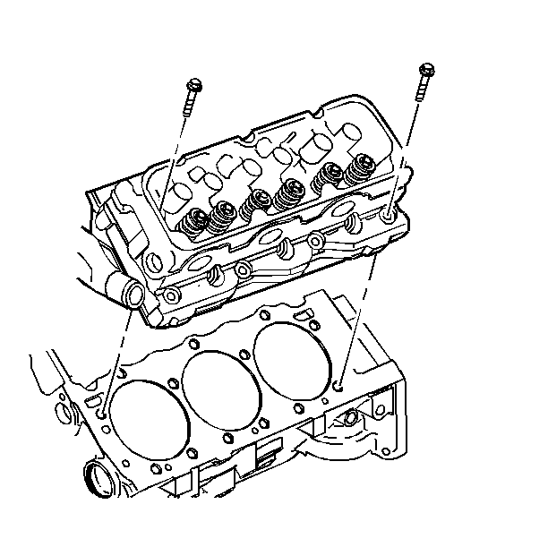
- Remove the cylinder head bolts.
- Remove the cylinder head.
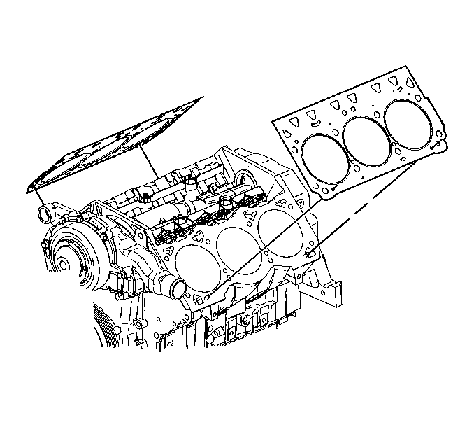
- Remove the cylinder head gasket.
- Clean the mating surfaces on the cylinder head, cylinder block and the intake manifold.
- Clean the cylinder block bolt hole threads using a 7/16-14 tap.


Installation Procedure
Special Tools
J 36660-A Torque Angle Meter
- Position the head gasket with the arrow pointing to the front of the engine.
- Install the cylinder head.
- Install the new cylinder head bolts.
- Install the left (front) push rods and rocker arms. Refer to Valve Rocker Arm and Push Rod Replacement .
- Install the left (front) valve rocker arm cover. Refer to Valve Rocker Arm Cover Replacement
- Install the left (front) exhaust manifold. Refer to Exhaust Manifold Replacement .
- Install the lower intake manifold (VIN K). Refer to Intake Manifold Replacement .
- Install the lower intake manifold (VIN 1). Refer to Intake Manifold Replacement .
- Install the upper intake manifold (VIN K). Refer to Intake Manifold Replacement .
- Install the supercharger (VIN 1). Refer to Supercharger Replacement .
- Install the right engine mount strut bracket. Refer to Engine Mount Strut Bracket Replacement .
- Install the air cleaner duct. Refer to Engine Controls.
- Install the fuel injector sight shield (VIN 1). Refer to Fuel Injector Sight Shield Replacement .
- Install the fuel injector sight shield (VIN K). Refer to Fuel Injector Sight Shield Replacement .
- Connect the battery ground (negative) cable. Refer to Battery.
- Fill the cooling system with coolant. Refer to Cooling and Radiator.
- Fill the engine with oil. Refer to Maintenance and Lubrication.
- Inspect for proper fluid levels.
- Inspect for leaks.
Notice: Head gaskets are not interchangeable. The head gasket must be installed with the arrow pointing to the front of the engine. Installing the head gasket in any other direction will cause gasket failure and possible engine failure.


Notice: This bolt is designed to permanently stretch when tightened, and therefore MUST be replaced anytime it is removed. The correct part number fastener must be used to replace this type of fastener. Do not use a bolt that is stronger in this application. If the correct bolt is not used, the parts will not be tightened correctly. The system or the components may be damaged.
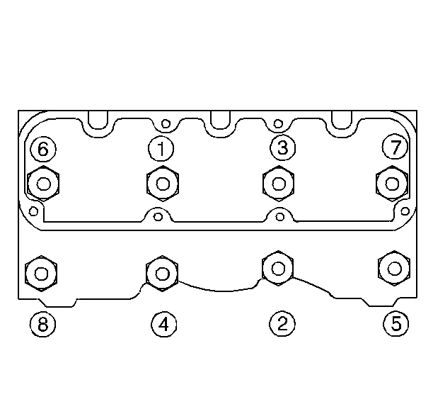
Notice: This engine uses special torque to yield head bolts. This design bolt requires a special tightening procedure. Failure to follow the given procedure will cause head gasket failure and possible engine damage.
Notice: Use the correct fastener in the correct location. Replacement fasteners must be the correct part number for that application. Fasteners requiring replacement or fasteners requiring the use of thread locking compound or sealant are identified in the service procedure. Do not use paints, lubricants, or corrosion inhibitors on fasteners or fastener joint surfaces unless specified. These coatings affect fastener torque and joint clamping force and may damage the fastener. Use the correct tightening sequence and specifications when installing fasteners in order to avoid damage to parts and systems.

Tighten
| • | Tighten the bolts in sequence to 50 N·m (37 lb ft). |
| • | Rotate each bolt 120 degrees in sequence. Use J 36660-A . |
| • | Rotate the center four bolts an additional 30 degrees. Use J 36660-A . |
Cylinder Head Replacement Right
Special Tools
J 36660-A Torque Angle Meter
Removal Procedure
- Disconnect the battery ground (negative) cable. Refer to
Caution: Unless directed otherwise, the ignition and start switch must be in the OFF or LOCK position, and all electrical loads must be OFF before servicing any electrical component. Disconnect the negative battery cable to prevent an electrical spark should a tool or equipment come in contact with an exposed electrical terminal. Failure to follow these precautions may result in personal injury and/or damage to the vehicle or its components.
. - Drain the coolant. Refer to Cooling and Radiator.
- Drain the engine oil.
- Remove the fuel injector sight shield (VIN K). Refer to Fuel Injector Sight Shield Replacement .
- Remove the fuel injector sight shield (VIN 1). Refer to Fuel Injector Sight Shield Replacement .
- Remove the air cleaner duct. Refer to Engine Controls.
- Remove the accessory drive belt tensioner. Refer to Drive Belt Tensioner Replacement .
- Remove the EGR valve. Refer to Engine Controls.
- Remove the lower intake manifold (VIN K). Refer to Intake Manifold Replacement .
- Remove the lower intake manifold (VIN 1). Refer to Intake Manifold Replacement .
- Remove the right (rear) exhaust manifold. Refer to Exhaust Manifold Replacement .
- Remove the right (rear) rocker arms and push rods. Refer to Valve Rocker Arm and Push Rod Replacement .
- Remove the cylinder head bolts.
- Remove the cylinder head.
- Remove the cylinder head gasket.
- Clean the mating surfaces on the cylinder head, cylinder block and the intake manifold.
- Clean the cylinder block bolt hole threads using a 7/16-14 tap.


Installation Procedure
- Position the head gasket with the arrow pointing to the front of the engine.
- Place the exhaust manifold in place.
- Install the cylinder head.
- Install the new cylinder head bolts.
- Tighten the bolts in sequence to 50 N·m (37 lb ft).
- Rotate each bolt 120 degrees in sequence. Use J 36660-A .
- Rotate the center four bolts an additional 30 degrees. Use J 36660-A .
- Install the right (rear) push rods and rocker arms. Refer to Valve Rocker Arm and Push Rod Replacement .
- Install the right (rear) valve rocker arm cover. Refer to Valve Rocker Arm Cover Replacement .
- Install the right (rear) exhaust manifold. Refer to Exhaust Manifold Replacement .
- Install the front exhaust pipe to the right (rear) manifold. Refer to Exhaust System.
- Install the lower intake manifold (VIN K). Refer to Intake Manifold Replacement .
- Install the lower intake manifold (VIN 1). Refer to Intake Manifold Replacement .
- Install the upper intake manifold (VIN K). Refer to Intake Manifold Replacement .
- Install the supercharger (VIN 1). Refer to Supercharger Replacement .
- Install the EGR valve. Refer to Engine Controls.
- Install the accessory drive belt tensioner. Refer to Drive Belt Tensioner Replacement .
- Fill the engine coolant. Refer to Cooling and Radiator.
- Install the air cleaner duct. Refer to Engine Controls.
- Install the fuel injector sight shield (VIN 1). Refer to Fuel Injector Sight Shield Replacement .
- Install the fuel injector sight shield (VIN K). Refer to Fuel Injector Sight Shield Replacement .
- Connect the battery ground (negative) cable. Refer to Battery.
- Fill the cooling system with coolant. Refer to Cooling and Radiator.
- Fill the engine with oil. Refer to Maintenance and Lubrication.
- Inspect for proper fluid levels.
- Inspect for leaks.
Notice: Head gaskets are not interchangeable. The head gasket must be installed with the arrow pointing to the front of the engine. Installing the head gasket in any other direction will cause gasket failure and possible engine failure.


Notice: This bolt is designed to permanently stretch when tightened, and therefore MUST be replaced anytime it is removed. The correct part number fastener must be used to replace this type of fastener. Do not use a bolt that is stronger in this application. If the correct bolt is not used, the parts will not be tightened correctly. The system or the components may be damaged.
Notice: This engine uses special torque to yield head bolts. This design bolt requires a special tightening procedure. Failure to follow the given procedure will cause head gasket failure and possible engine damage.
Notice: Use the correct fastener in the correct location. Replacement fasteners must be the correct part number for that application. Fasteners requiring replacement or fasteners requiring the use of thread locking compound or sealant are identified in the service procedure. Do not use paints, lubricants, or corrosion inhibitors on fasteners or fastener joint surfaces unless specified. These coatings affect fastener torque and joint clamping force and may damage the fastener. Use the correct tightening sequence and specifications when installing fasteners in order to avoid damage to parts and systems.

Tighten
