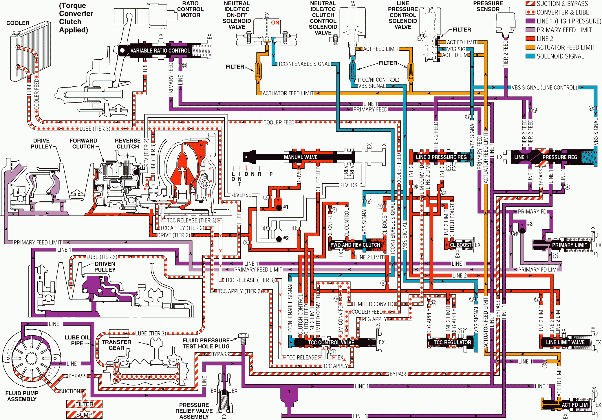
When the transmission control module (TCM) determines that the engine and transmission are operating properly to engage the torque converter clutch (TCC), the TCM energizes the Neutral Idle/TCC On-Off solenoid valve and regulates the duty cycle of the Neutral Idle/TCC Clutch Control solenoid valve.
At this time the Torque Converter Clutch is considered to be disengaged - OFF, and the Neutral Idle/TCC On-Off solenoid valve is OFF, the Neutral Idle/TCC Clutch Control solenoid valve maintains a 90% duty cycle.
Important: The Neutral Idle/TCC Clutch Control solenoid valve operates independently from the Neutral Idle/TCC On-Off solenoid valve. The Neutral Idle/TCC On-Off solenoid valve only controls when the TCC is applied. When the Neutral Idle/TCC On-Off solenoid valve is ON, the Neutral Idle/TCC Clutch Control solenoid valve only controls the fluid pressure used to apply the TCC.
Important: Under normal operating conditions the torque converter clutch is in the released position while the transmission is operating in the Intermediate or Low Ranges. However, when the transmission fluid temperatures exceed approximately 121°C (250°F), the TCM will apply the torque converter clutch in Intermediate or Low Range to help reduce fluid temperatures.
The following events occur in order to apply the torque converter clutch:
Stage 1: The TCM immediately decreases the Neutral Idle/TCC Clutch Control solenoid valve duty cycle to 0% - from point S to point A, then pulses the Neutral Idle/TCC Clutch Control solenoid valve to approximately 25% duty cycle from point B to point C. Actuator feed limit fluid at the Neutral Idle/TCC Clutch Control solenoid is "pulsed" into the VBS signal - TCC/NI control, fluid circuit. The VBS signal - TCC/NI control, fluid pressure at point C regulates a line pressure branch which creates regulated apply fluid. The TCM also energizes the Neutral Idle/TCC On-Off solenoid valve, allowing actuator feed limit fluid to pass through the solenoid and enter the TCC/NI enable signal circuit. TCC/NI enable signal fluid is routed to the TCC control valve, and overcomes spring force, in order to shift the valve to the apply position. With the TCC control valve in the apply position, release fluid can exhaust through the valve. This stage is designed to move the TCC control valve from the released to the applied position; there is not yet enough pressure to apply the TCC.Stage 2: The Neutral Idle/TCC Clutch Control solenoid valve duty cycle is ramped up from point C to point D to approximately 50%. Regulated apply fluid pressure is now strong enough to cause the converter apply to occur. Line 2 limit pressure enters the regulated apply circuit at the TCC regulator valve. Regulated apply fluid is routed through the TCC control valve into the TCC apply fluid circuit. The pressure value in the regulated apply circuit should now be high enough to fully apply the TCC pressure plate. Slip speed should be at the correct value - near "0". In vehicles equipped with the Electronically Controlled Clutch Capacity (ECCC) system, the pressure plate does not fully lock to the torque converter cover. It is instead precisely controlled to maintain a small amount of slippage between the engine and the turbine, reducing driveline torsional disturbances.
Stage 3: If it is determined by the TCM that it is desirable to fully lock the TCC, regulated apply fluid pressure is increased. This is caused by the Neutral Idle/TCC Clutch Control solenoid valve duty cycle being increased from point E to point F, to approximately 98%. This extra pressure ensures that the apply force on the TCC pressure plate is not at the slip threshold, but a little above it. TCC plate material is therefore protected from excessive heat.
Drive, Intermediate and Low Range - TCC Applied

