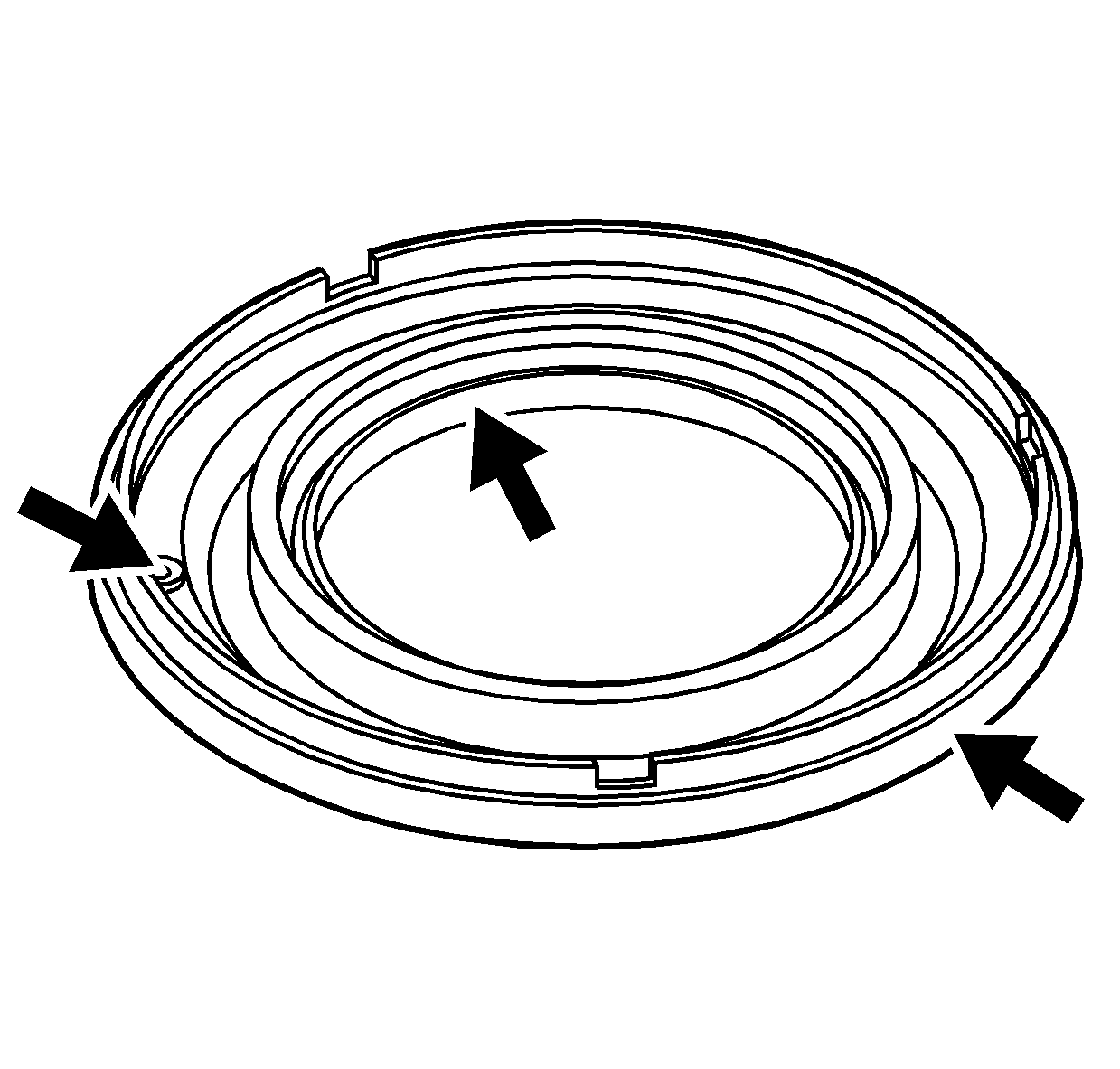
- Inspect the forward clutch piston assembly
for cuts, nicks or damage.
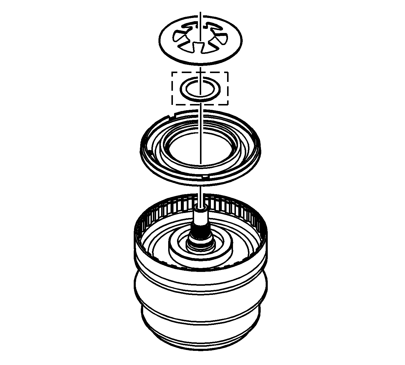
Important: The forward clutch piston assembly may be
carefully pressed into the drive pulley assembly by hand.
- Install the forward clutch piston assembly into the drive pulley assembly.
- Install the forward clutch spring washer - some models.
- Install the forward clutch piston spring.
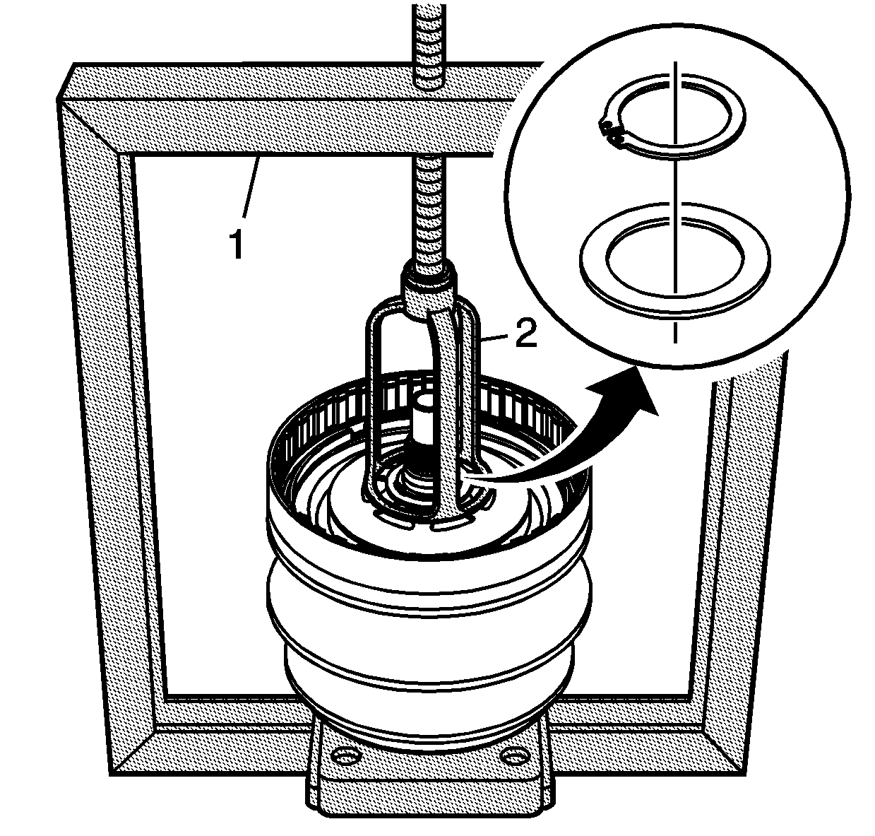
- Using the J 23456
(1) and the J 43074
(2), compress the forward clutch piston spring.
- Install the forward clutch spring washer.
Important: Ensure that the retaining ring is properly
seated in the snap ring groove of the variable drive pulley assembly.
- Install the retaining ring for the forward clutch piston spring.
- Remove the J 23456
and
the J 43074
.
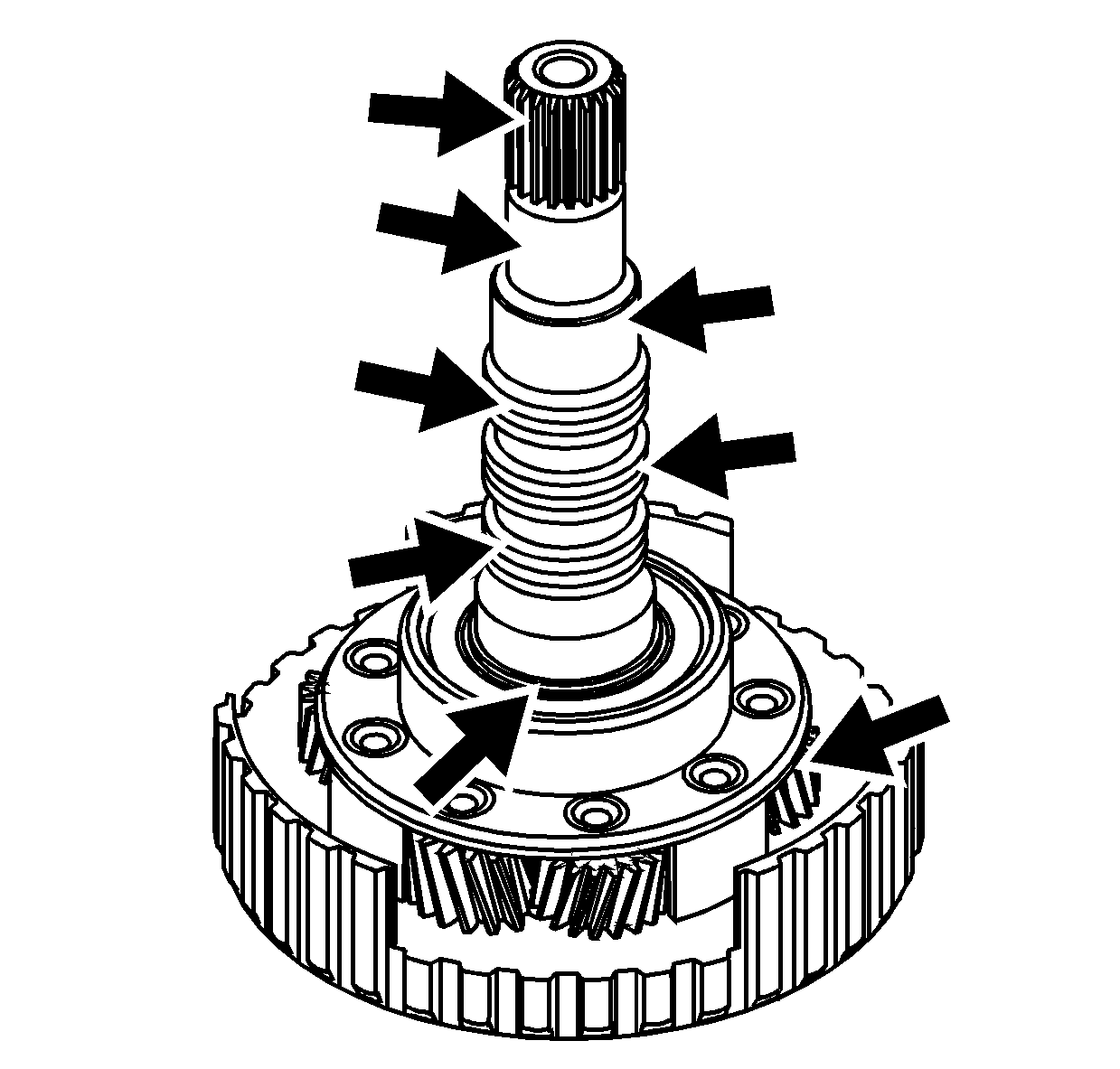
- Inspect the input shaft carrier assembly
for the following conditions:
| • | Damaged or worn journals on the input shaft |
| • | Damaged or worn splines on the input shaft |
| • | Damaged or worn pinion gear teeth |
| • | Damaged or worn thrust washers |
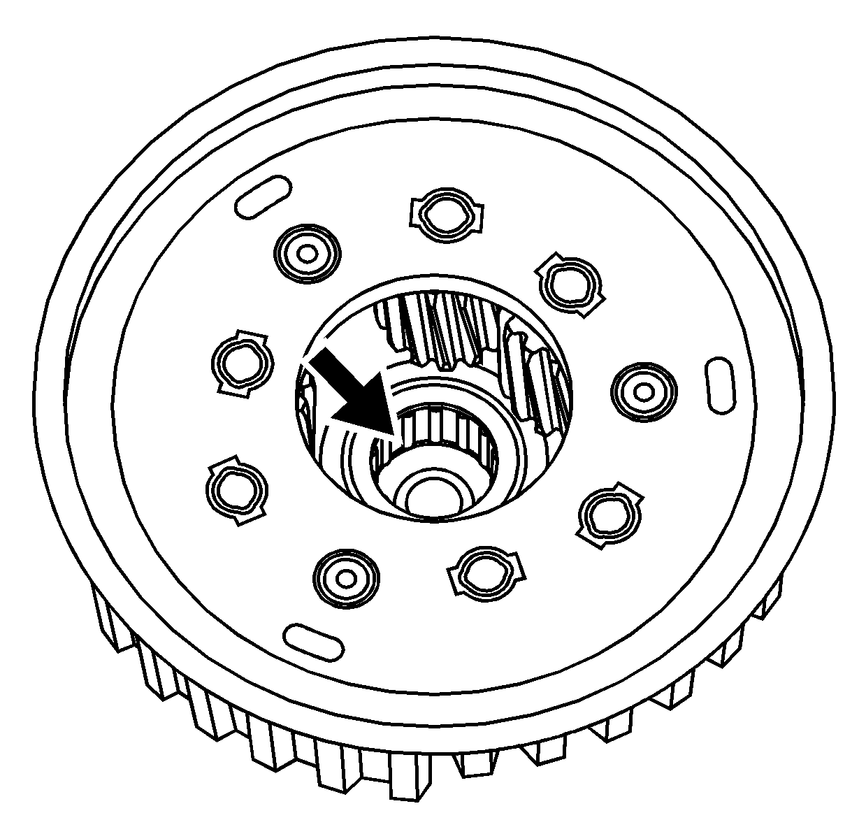
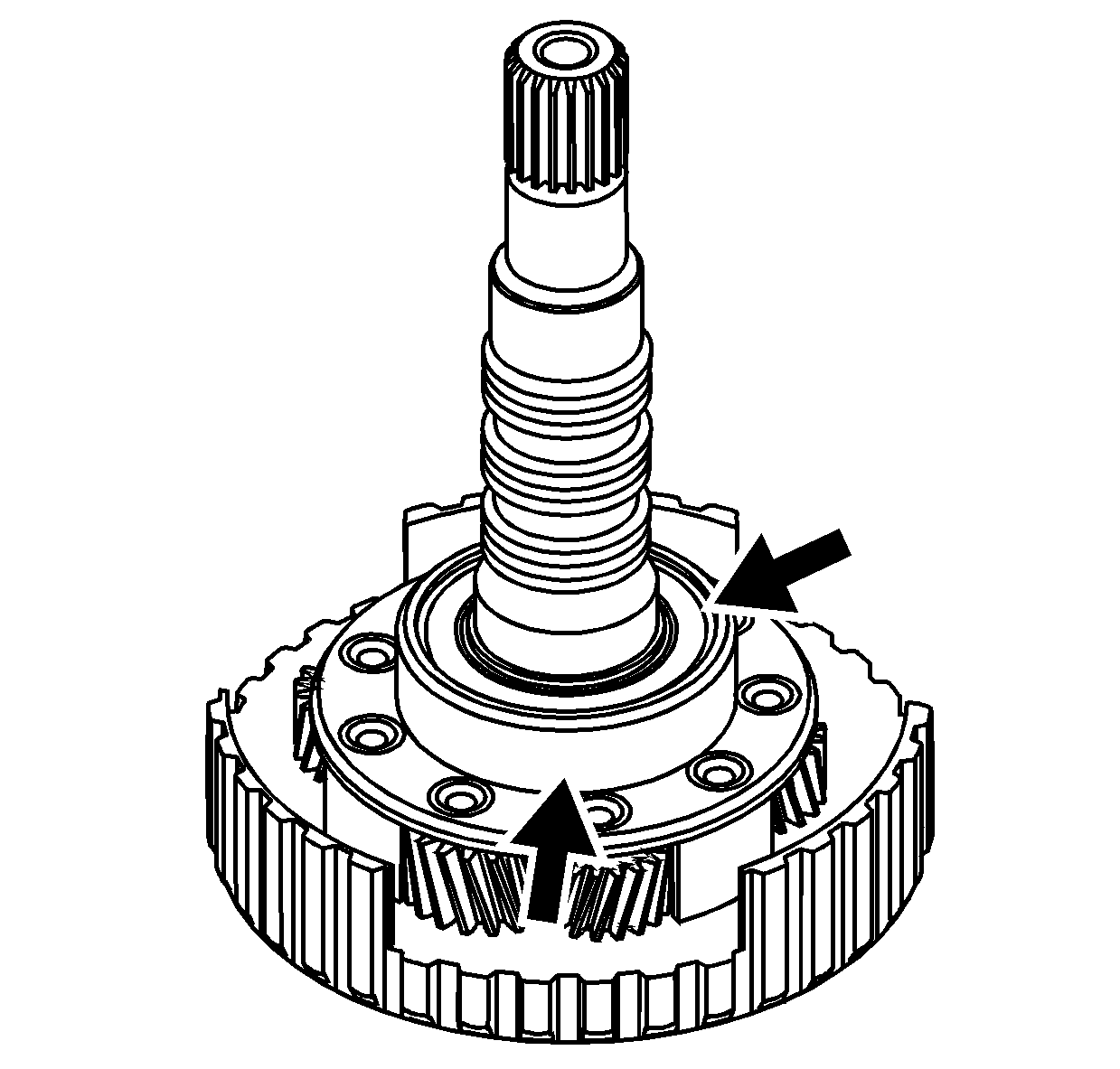
- Inspect the input shaft - inner -
bearing assembly for damage or wear.
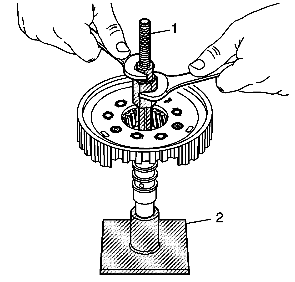
Important: Perform steps 10 through 12 only if replacing
the input shaft - inner - bearing assembly.
- With the input shaft installed into the J 43083
(2), tighten the J 44998
(1), into the input shaft - inner - bearing assembly.
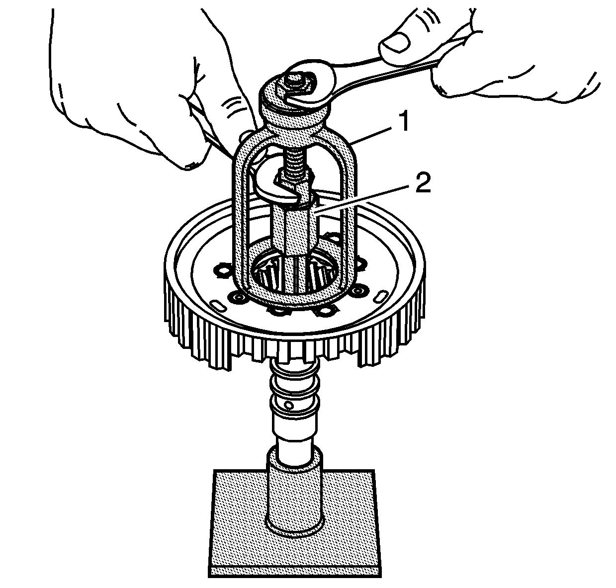
- Using the J 43074
(1) and the J 44998
(2), remove the input shaft - inner - bearing
assembly.
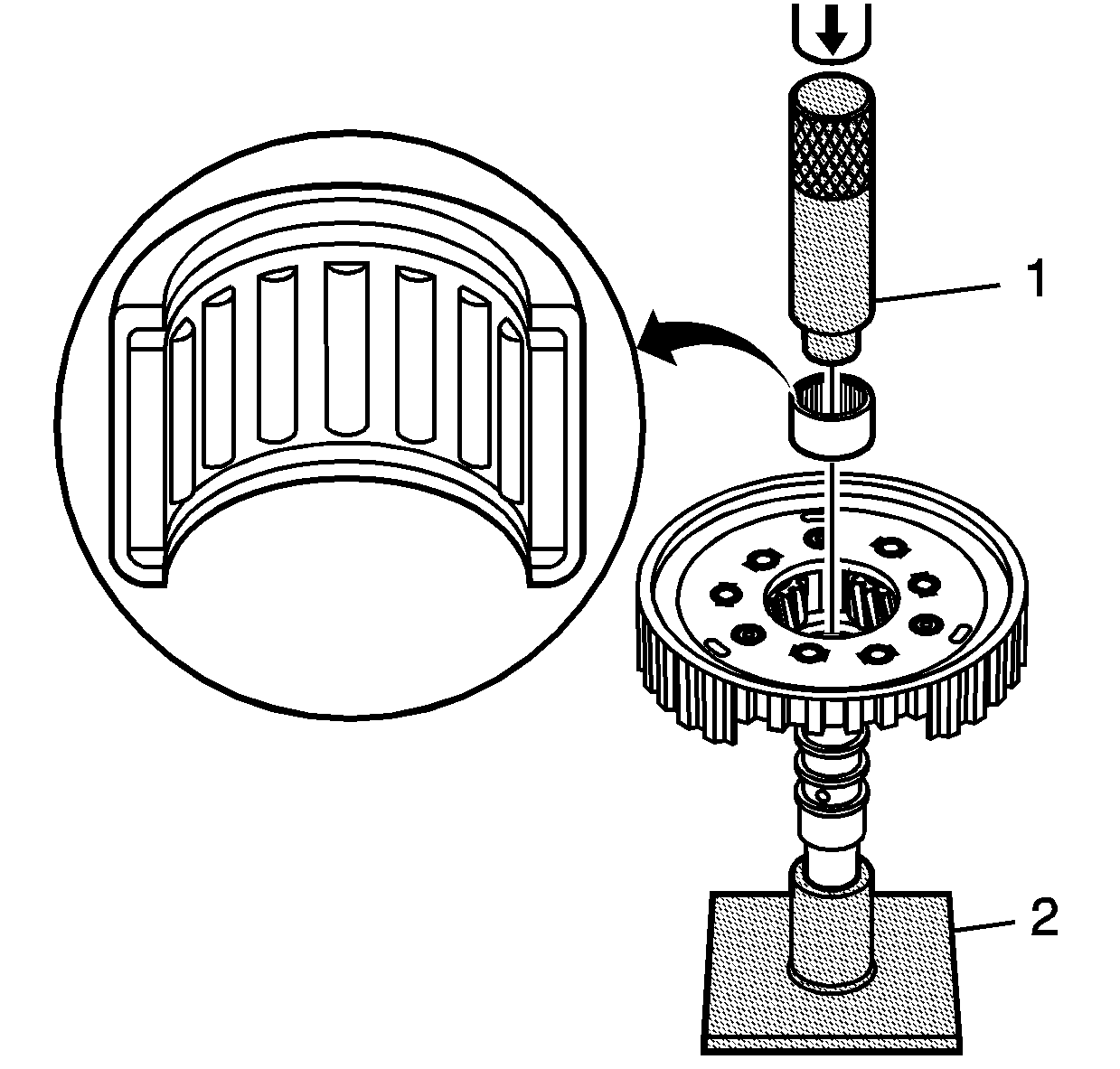
Important: When installing the NEW input shaft -
inner - bearing assembly, press the flat end of the bearing shell. The flat
end of the bearing shell is slightly thicker than the other end.
- Using the J 43083
(2), J 43060
(1) and an arbor press,
install a NEW input shaft - inner - bearing assembly.
- Inspect the input shaft - outer -
bearing assembly for damage or wear.
Important: Perform steps 14 and 15 only if replacing
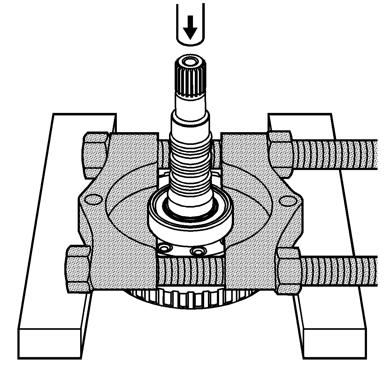
the input shaft - outer - bearing assembly.
- Using the J 22912-B
and
an arbor press, remove the input shaft - outer - bearing assembly.
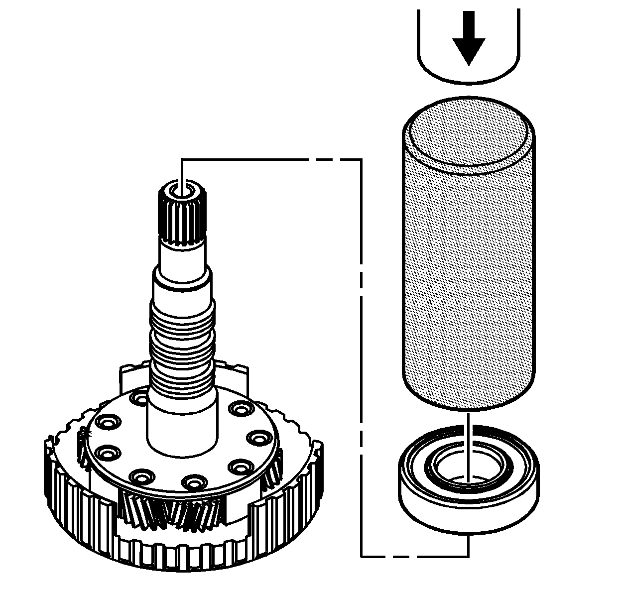
Important: The input shaft - outer - bearing
must rotate freely after installation.
- Using the J 6133-A
and
an arbor press, install a NEW input shaft - outer - bearing assembly.
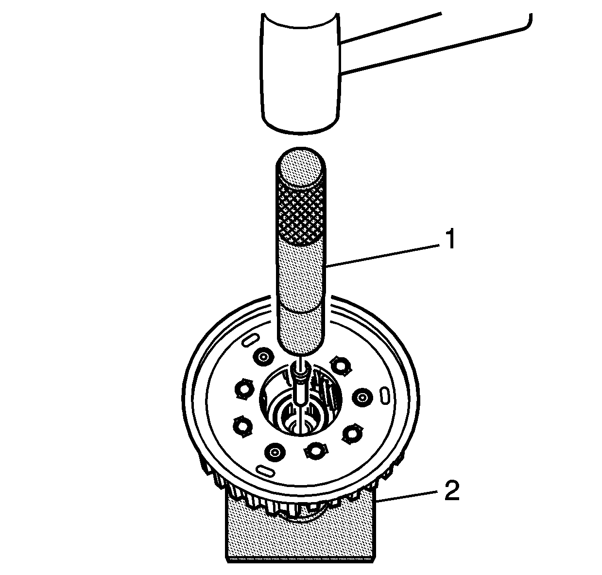
- Using the J 43083
(2), J 44939
(1) and a hammer, install a NEW fluid passage sleeve.
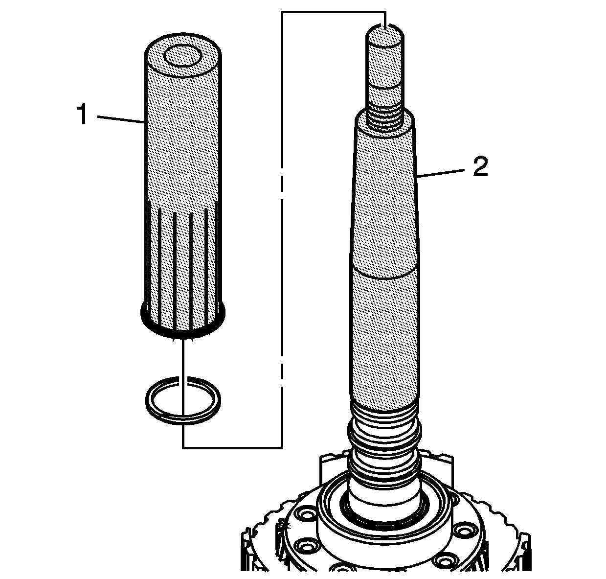
Important: When installing the 3 teflon fluid
seal rings onto the input shaft, begin with the seal closest to the input carrier
assembly.
- Slide the J 43063-1
(2)
over the input shaft and position the J 43063-1
at the appropriate seal groove. Coat the J 43063-1
with transmission fluid.
- Guide a NEW seal onto the J 43063-1
.
- Using the J 43063-2
(1),
slide the seal into the seal groove.
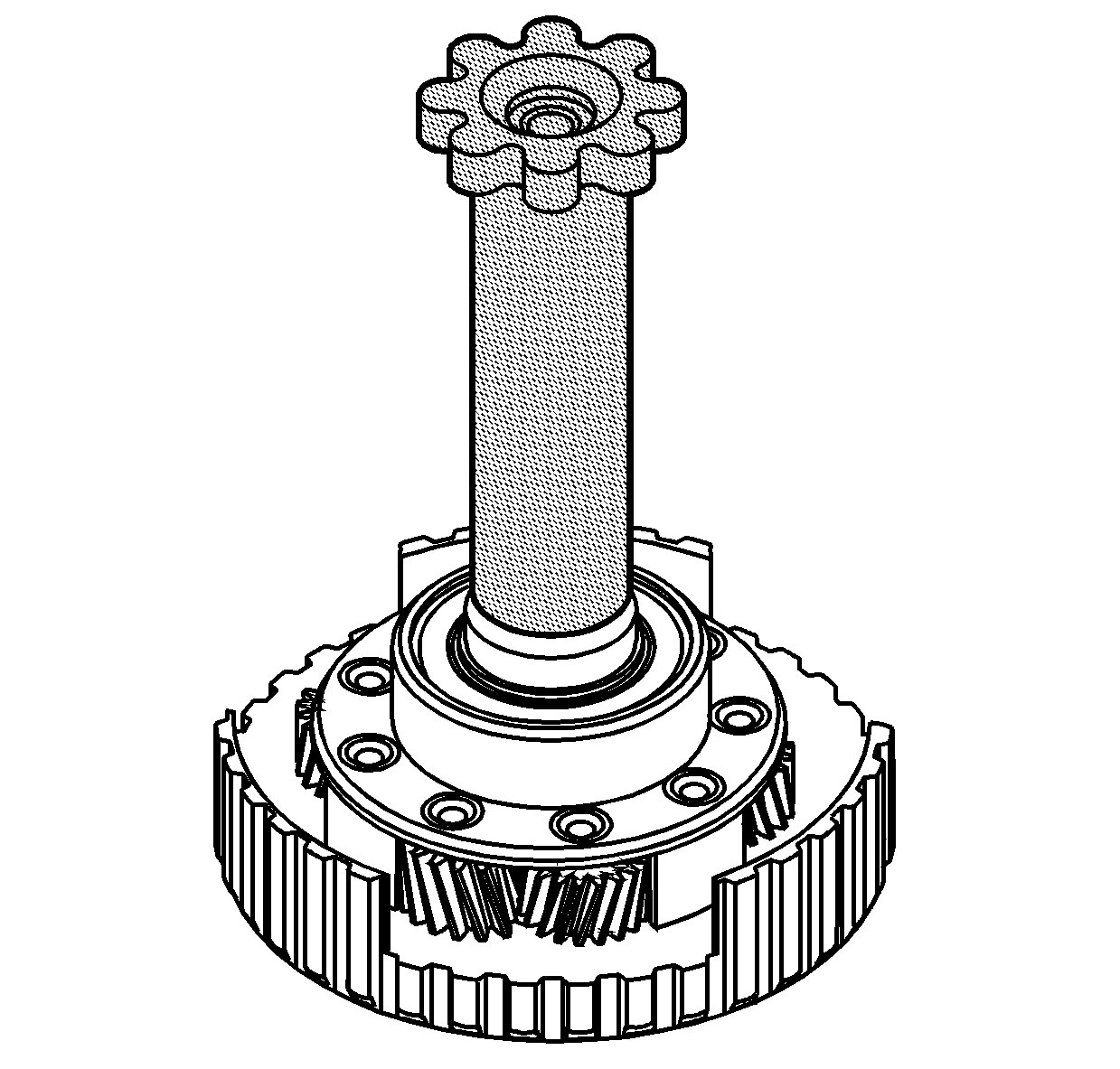
Notice: Size only 1 seal at a time. Sizing more than 1 seal at the same time
will result in damage to the seals.
Important: Allow each seal to shrink momentarily before
using the J 43063-3
. It may
be necessary to manipulate the seal with your fingers in order to decrease the outside
diameter of the seal.
Important: Ensure the J 43063-3
bottoms out on the input shaft.
- Using the J 43063-3
,
size the fluid seal ring.
- Leave the J 43063-3
in
place for at least 5 minutes in order to properly size the fluid seal ring.
- Repeat steps 17 through 21 for each seal.
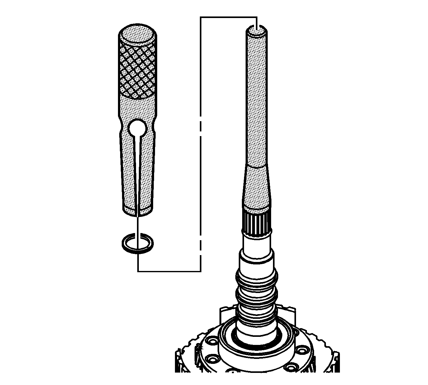
- Using the J 43084
, install a NEW split spiral fluid seal ring on the input shaft.
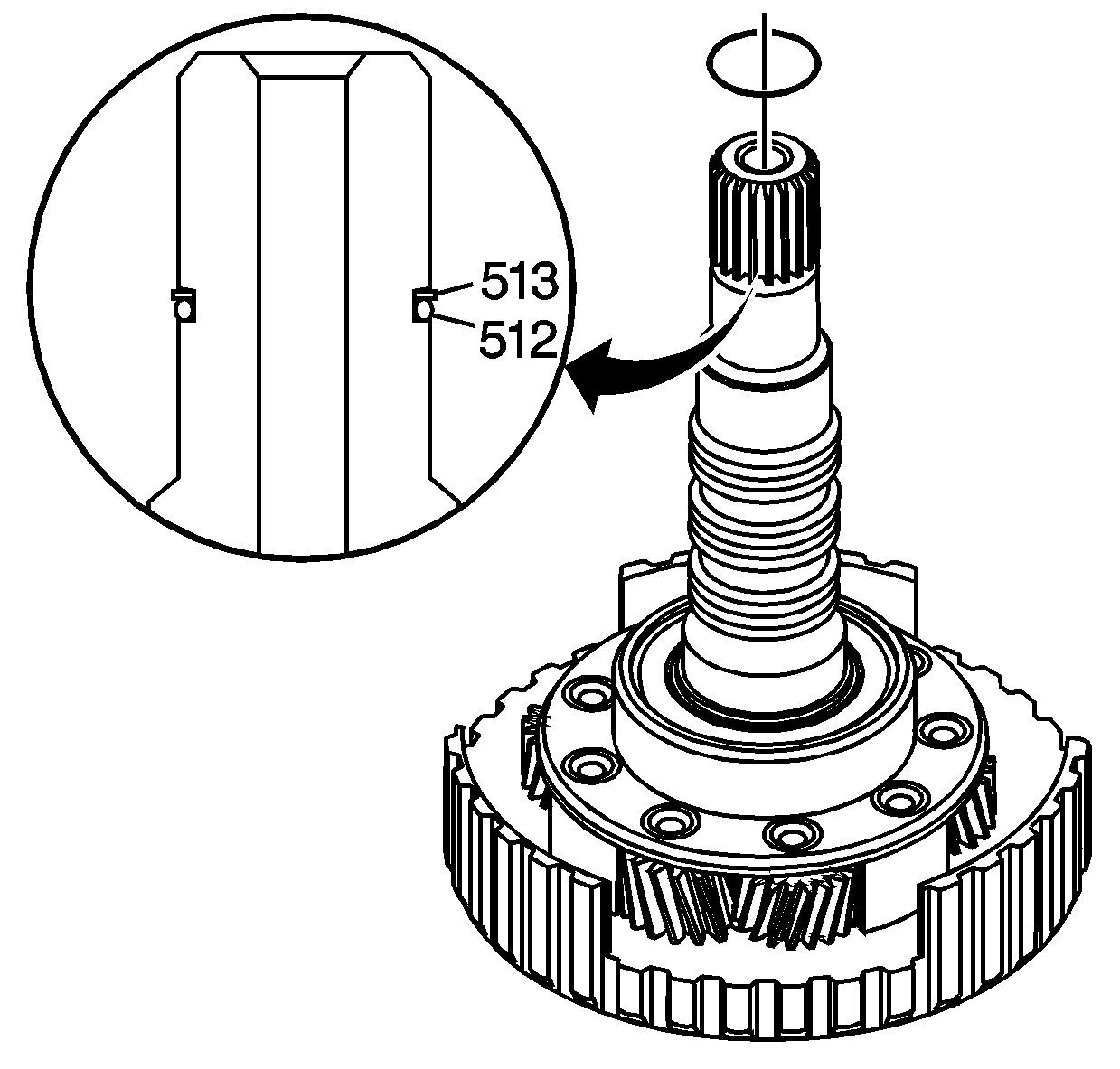
Important: Ensure that the input shaft O-ring
seal (512) is positioned below the fluid seal ring - split spiral ring (513).
- Install a NEW input shaft O-ring seal. Apply J 36850
to the seal.
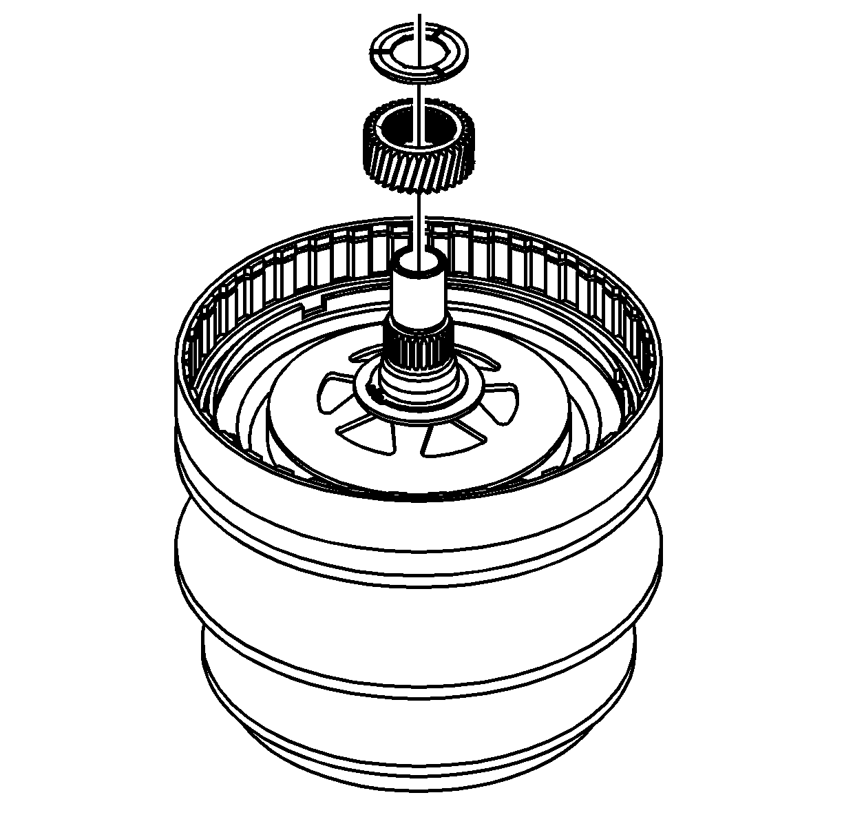
- Install the sun gear thrust washer on the
drive pulley assembly.
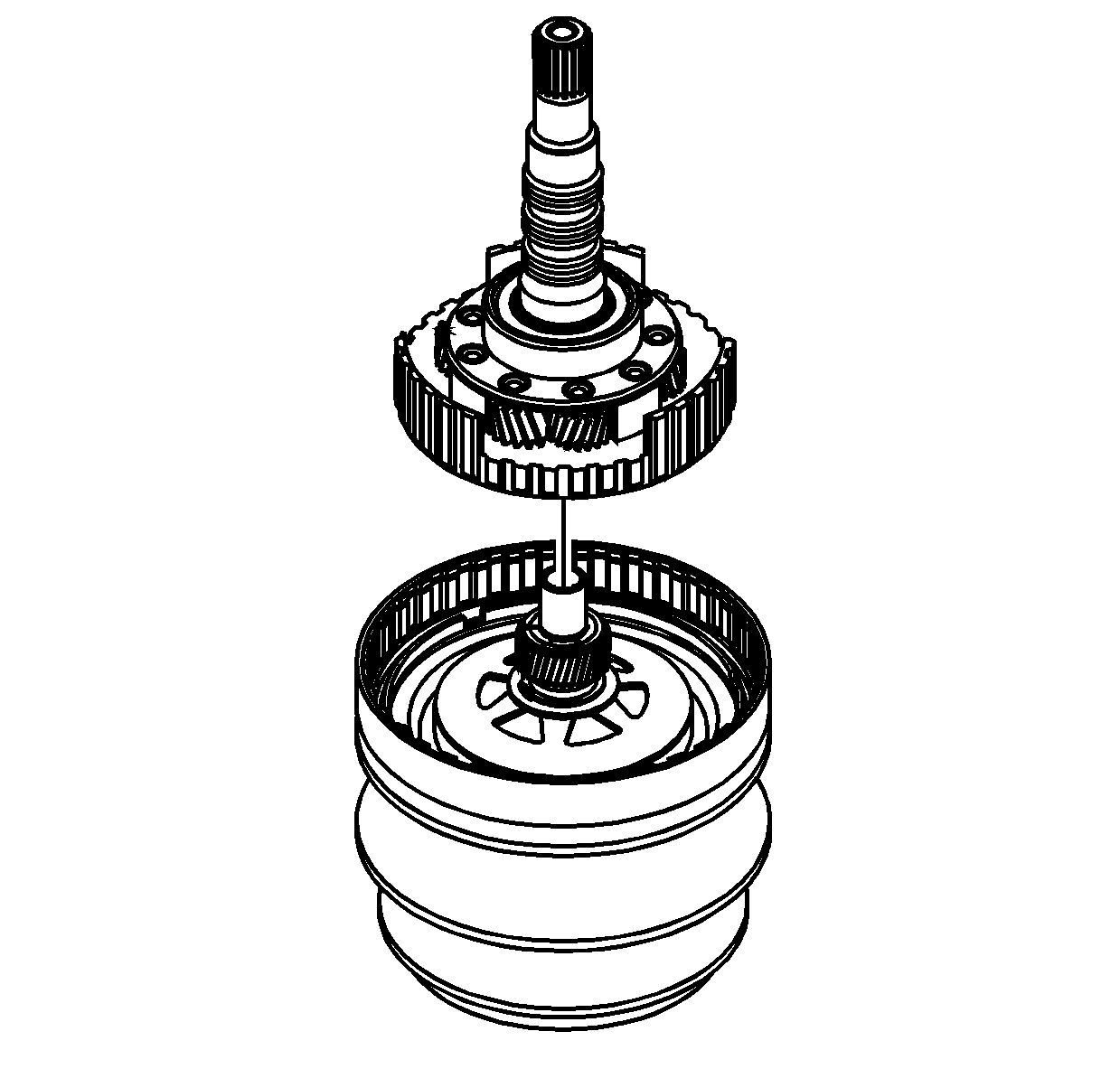
- Carefully install the input shaft assembly
on the drive pulley assembly. Align the input carrier pinion gears over the sun gear.
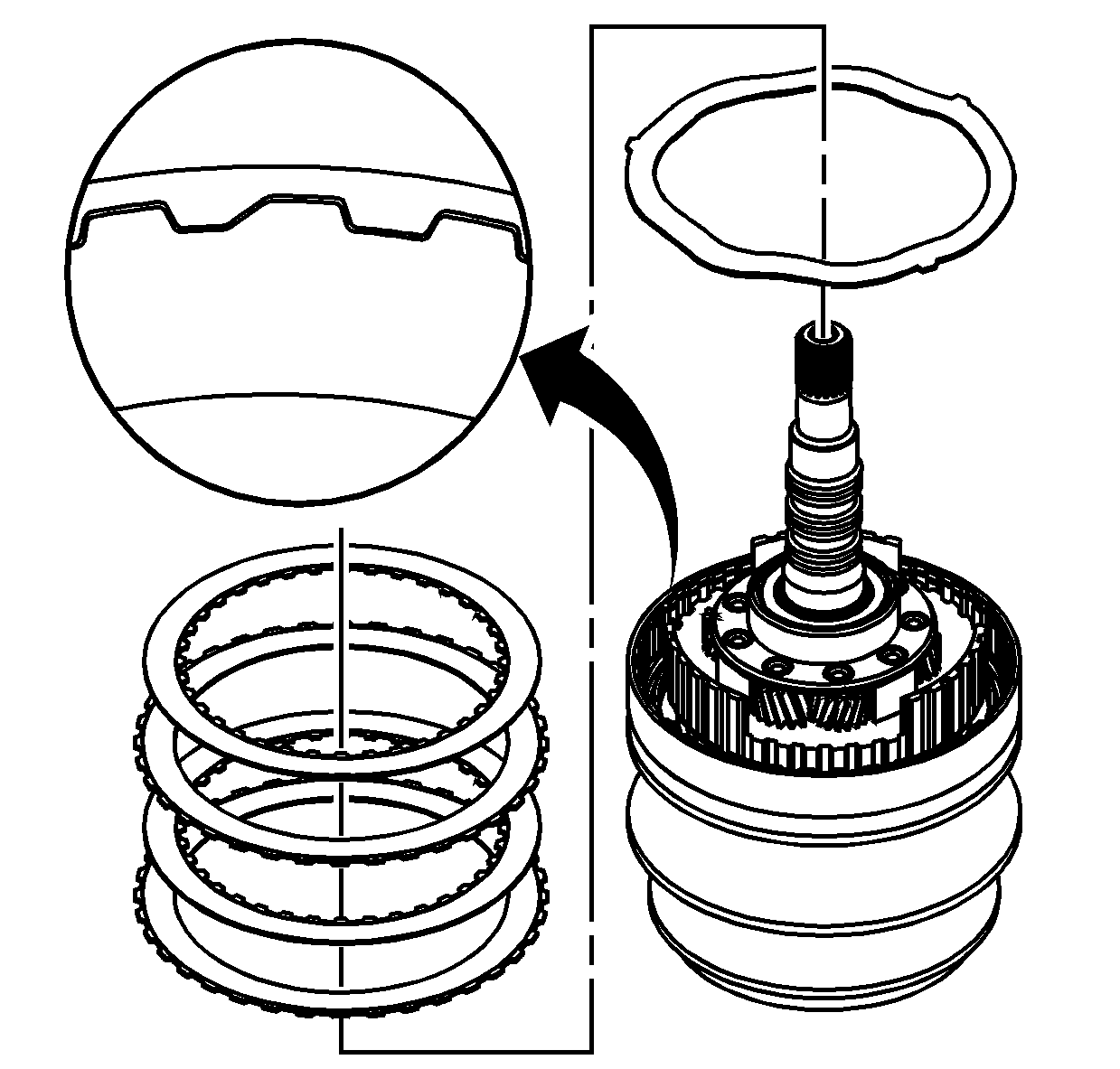
- Install the forward clutch waved plate.
Important: The forward clutch plates are designed to
fit only one way in the forward clutch assembly. Match the alignment notches on the
clutch plates with the corresponding notches on the forward clutch assembly and the
input shaft assembly.
Important: Install the forward clutch plates with the
friction material facing up, towards the backing plate.
- Install the forward clutch plates, two each, starting with a plate with the
splines on the outer, external, diameter.
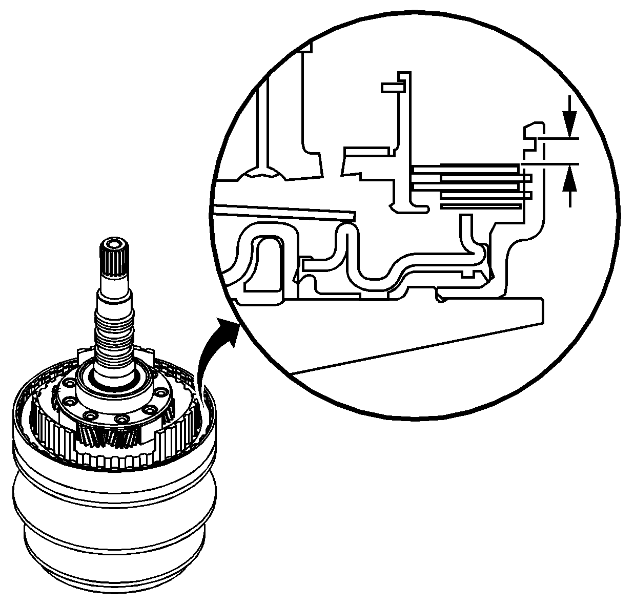
- Measure the distance between the top outer
edge of the retaining ring groove and the top friction plate.
Record
the measurement.
Important: The backing plate identification letter is
stamped on the backing plate.
- Refer to the
Forward Clutch Backing Plate Specifications
table in Specifications in order to select the proper packing plate.
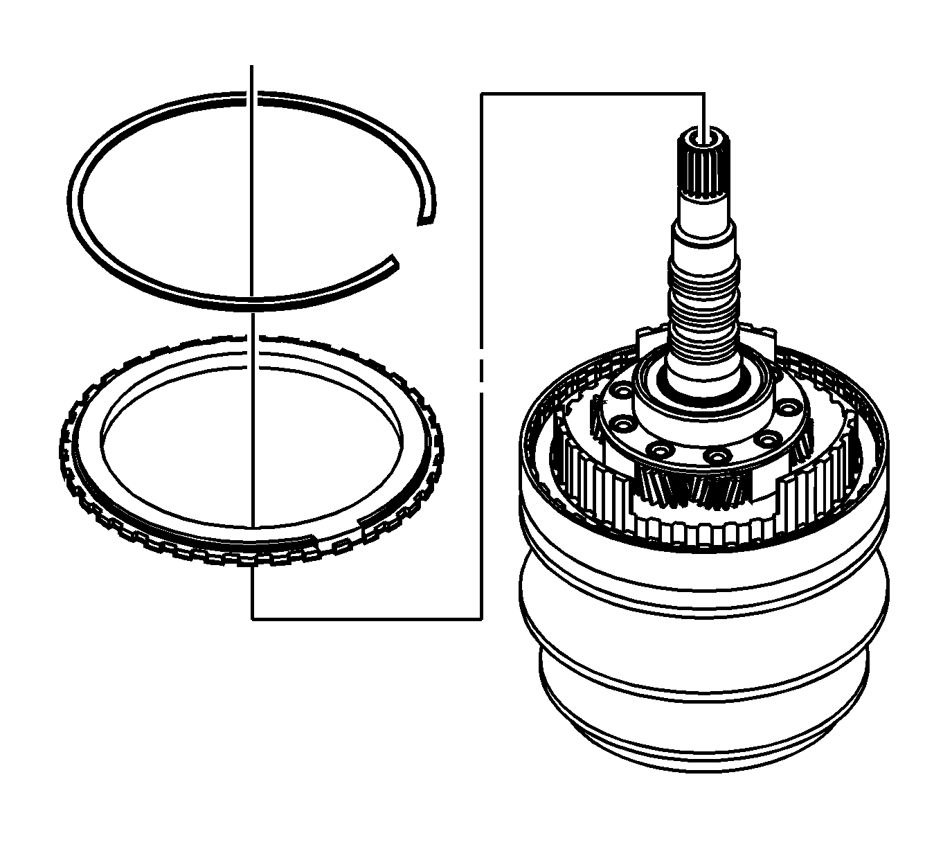
- Install the forward clutch backing plate.
- Install the retaining ring for the forward clutch backing plate.
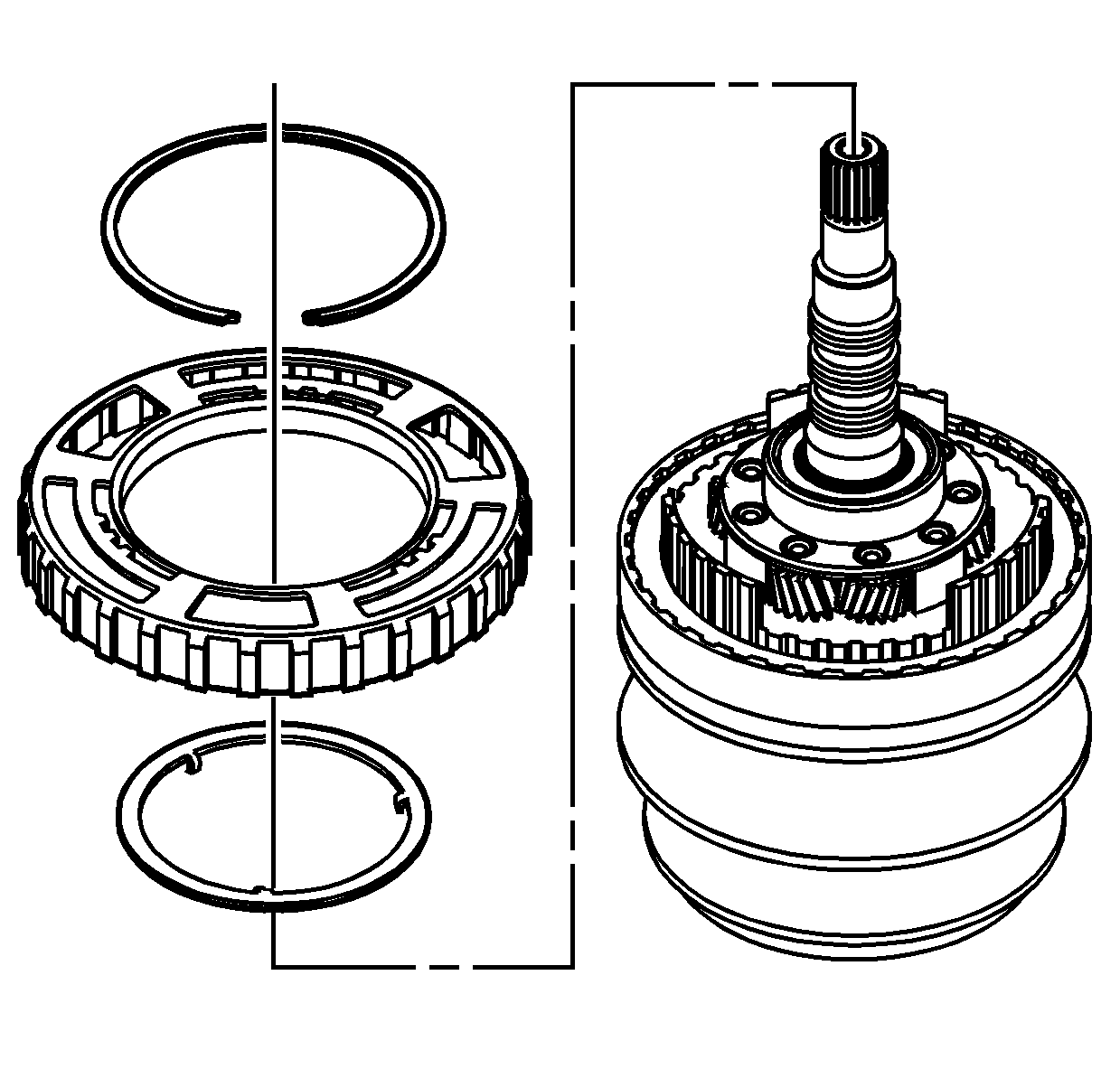
- Install the internal gear thrust washer,
tabs down.
- Install the speed sensor reluctor ring.
- Install the retaining ring for the speed sensor reluctor ring.


