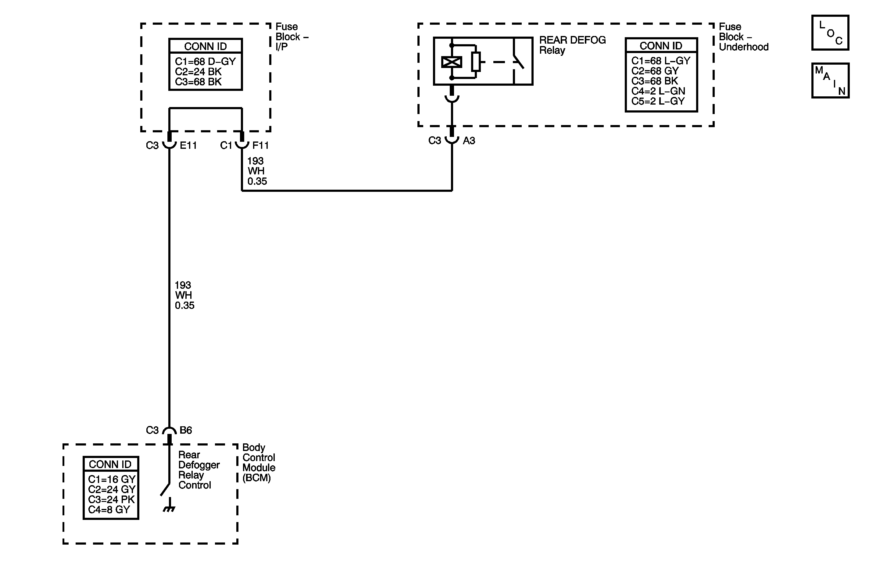
Circuit Description
The body control module (BCM) monitors the rear defogger switch input. When the rear defogger is turned on, rear defog switch closed, the BCM grounds the coil side of the rear defog relay. This will energize the relay activating the rear defogger.
The first time that the rear defogger is activated in an ignition cycle, the rear defogger will remain on for 15 minutes, or until the ignition switch is turned off. If the rear defogger is activated again during the same ignition cycle, the rear defogger will remain on for 7 1/2 minutes, or until the ignition switch is turned off.
Conditions for Running the DTC
The ignition is in RUN.
Conditions for Setting the DTC
| • | The rear defogger relay control circuit is shorted to battery voltage. |
| • | The BCM is commanding the rear defog system to the on state. |
Actions Taken When the DTC Sets
| • | No light will illuminate in the I/P. |
| • | When a shorted to battery voltage condition exists in the rear defogger relay control circuit and the BCM has been requested to activate the rear defog system, the BCM will attempt to switch the rear defogger relay control circuit. High current flow will result and the BCM output will go into a protective state. The BCM output will not allow itself to be activated for as much as 3 minutes. |
Conditions for Clearing the DTC
| • | This DTC will change from current to history when the fault is no longer present. |
| • | A history DTC will clear after 100 consecutive ignition cycles if the condition for the malfunction is no longer present. |
Step | Action | Yes | No |
|---|---|---|---|
Connector End View Reference: Master Electrical Component List in Wiring Systems | |||
1 | Did you perform the Defogger Diagnostic System Check? | Go to Step 2 | |
2 |
Do you hear a click when you command the REAR DEFOG relay ON and OFF? | Go to Testing for Intermittent Conditions and Poor Connections in Wiring Systems | Go to Step 3 |
3 |
Does the test lamp turn ON and OFF with each command? | Go to Step 5 | Go to Step 4 |
4 | Test the rear defog relay control circuit of the REAR DEFOG relay for a short to voltage. Refer to Circuit Testing and Wiring Repairs in Wiring Systems. Did you find and correct the condition? | Go to Step 9 | Go to Step 6 |
5 | Inspect for poor connections at the REAR DEFOG relay. Refer to Testing for Intermittent Conditions and Poor Connections and Connector Repairs in Wiring Systems. Did you find and correct the condition? | Go to Step 9 | Go to Step 7 |
6 | Inspect for poor connections at the harness connector of the BCM. Refer to Testing for Intermittent Conditions and Poor Connections and Connector Repairs in Wiring Systems. Did you find and correct the condition? | Go to Step 9 | Go to Step 8 |
7 | Replace the REAR DEFOG relay. Refer to Relay Replacement in Wiring Systems. Did you complete the replacement? | Go to Step 9 | -- |
8 |
Important: Perform the programming or setup procedure for the replaced control module if required. Replace the BCM. Refer to Body Control Module Replacement in Body Control System for applicable replacement procedure. Did you complete the replacement? | Go to Step 9 | -- |
9 |
Does the DTC reset? | Go to Step 2 | System OK |
