Replacement of Rear Drive Module (RDM) Differential Clutch Drum

| Subject: | REPLACEMENT OF REAR DRIVE MODULE (RDM) DIFFERENTIAL CLUTCH DRUM |
| Models: | 2004 SATURN VUE VEHICLES EQUIPPED WITH A 3.5L V6 (L66) ENGINE AND ALL-WHEEL DRIVE |
| Attention: | ALL U.S. SATURN RETAILERS AND AUTHORIZED SERVICE PROVIDERS |
THE CANADIAN VERSION OF THIS RECALL FOLLOWS THIS VERSION.
The Rear Drive Module (RDM) on some 2004 Saturn VUE vehicles equipped with a 3.5L V6 (L66) engine and all-wheel drive may exhibit a condition where the owner may notice a moan or vibration noise emanating from the rear of the vehicle when turning at low speeds (such as parking lot maneuvers and/or surfaces like snow and gravel).
To prevent the possibility of this condition occurring, Saturn retailers will replace the differential clutch drum in the rear drive module (RDM) and replace the RDM filter. This service will be performed at no cost to the owner.
Vehicles Involved
2004 model year Saturn VUE vehicles equipped with a 3.5L V6 (L66) engine and all-wheel drive within the following VIN range will require participation in this program.
4S800001 - 4S892254
You must verify program involvement through your AS400 system. It is important to note that program claims will only be paid on involved vehicles.
Owner Notification
Owners of all involved vehicles will be notified of this customer satisfaction program by Saturn when parts are sufficient. (Refer to the owner letter included in this bulletin.)
Transfer of Customer Service Program Responsibility
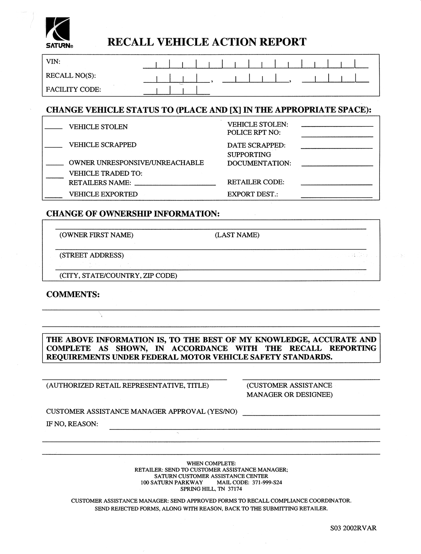
Saturn vehicles that have been sold by you, which may be closer in proximity to another Saturn Retailer, may still appear on your Facility VIN Listing. If you determine that it is more desirable for a vehicle on your Facility VIN Listing to be serviced by another Saturn Retailer, responsibility may be transferred by completing a Recall Vehicle Action Report and submitting it to your Customer Assistance Manager (CAM) at the Saturn Customer Assistance Center.
A copy of the Recall Vehicle Action Report is included for your reference. Additional copies can be ordered from Saturn Publications (1-800-828-2112, prompt 3, Item # S03 2002 RVAR). All changes to program responsibility will be reflected in your next Unfixed VIN Report.
All other changes in vehicle status (e.g., scrapped, stolen, etc.) are to be made in accordance with section 4.4.3 of the Retailer Service Reference Guide, "Notifying Saturn of Vehicle Status Change."
Parts Information
Saturn Service Parts Operations (SSPO) will be shipping all non-chemical parts as they become available based on the affected vehicle population at your retail facility. Please do not order extra inventory of these parts or modify your existing stocking policies. Normal replenishment will continue to support your current stocking policy requirements.
Part Number | Description | Qty/ Vehicle |
|---|---|---|
15235314 | Limited Slip Differential Drum | 1 |
12569934 | Differential Oil Filter | 1 |
U.S.A. 21005994 Canada 10953488 | Loctite® Threadlocker 262 or Permatex 27200 | $5.85 per vehicle *Billed as Net Item "M" |
12569951 | Differential Pinion Gear Nut | 1 |
U.S.A. 21019581 Canada 10953472 | Sealant - Right Stuff/Loctite® 5900 | $1.65 Per vehicle **Billed as Net Item "M" |
U.S.A. 12378514 Canada 88901045 | Rear Axle Lubricant (GM Versatrak® Fluid) | 1.5 bottles |
U.S.A. 21485278 Canada 10953480 | Loctite® Threadlocker 592 | $2.09 per vehicle ***Billed as Net Item "M" |
* 1 tube will service 3 vehicles. One tube $17.56 / 3 vehicles = $5.85 per vehicle.
** 1 tube will service 10 vehicles. One tube $16.53 / 10 vehicles = $1.65 per vehicle.
*** 1 tube will service 10 vehicles. One tube $20.86 / 10 vehicles = $2.09 per vehicle.
Total Material Allowance is $9.59 per vehicle.
Disposition of Replaced Parts
Retailers will scrap all replaced parts in a manner that ensures that they cannot be reused, remanufactured, or otherwise entered into the stream of commerce in the future.
Service Procedure
Removal Procedure
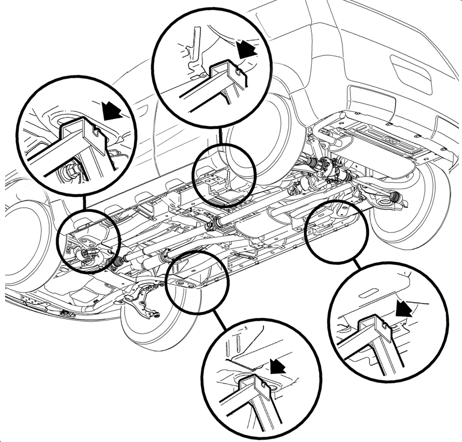
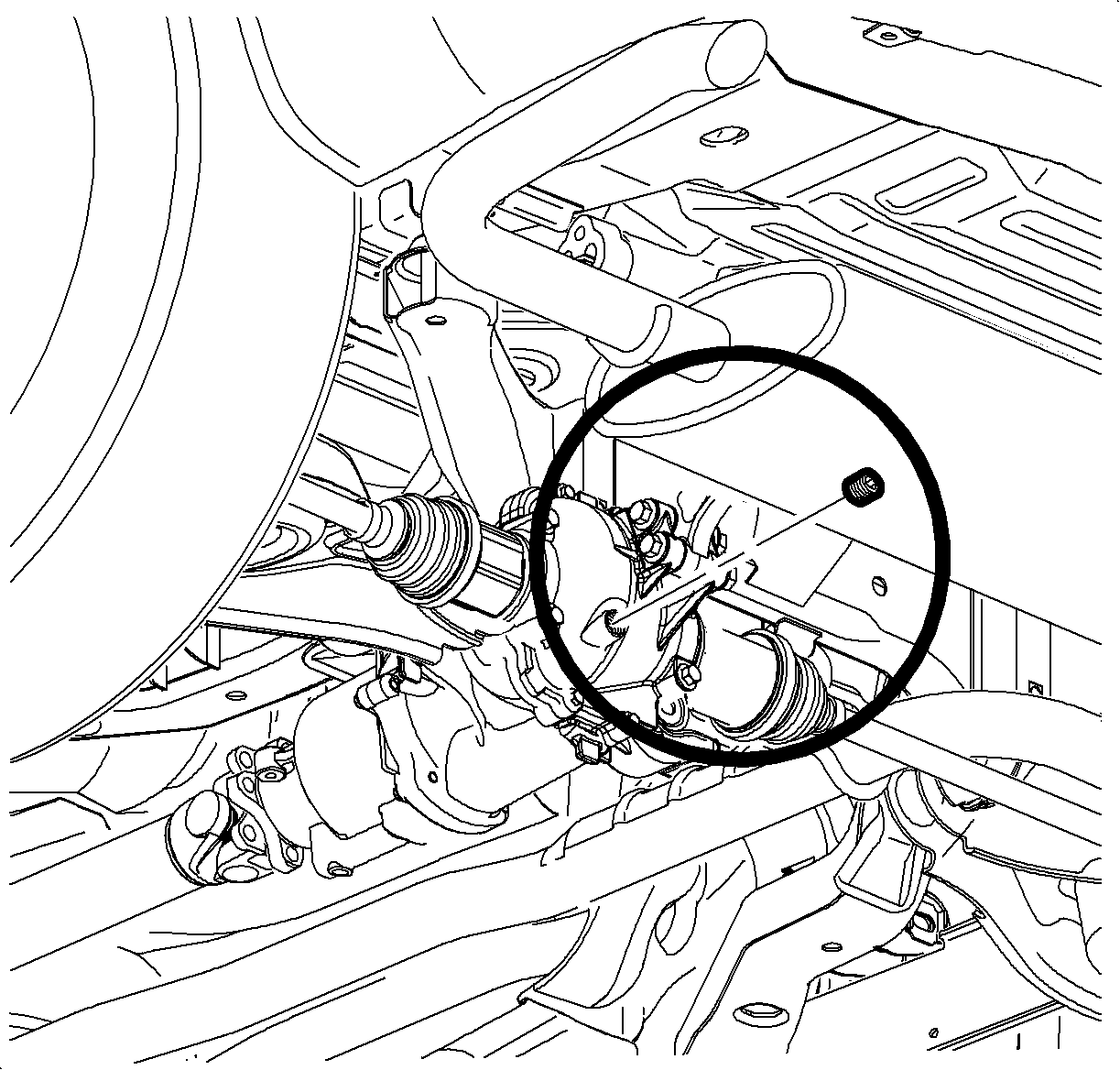
- Raise and support the vehicle. (Refer to illustration.)
- Place a container under the RDM housing.
- Remove the RDM drain plug and drain the fluid.
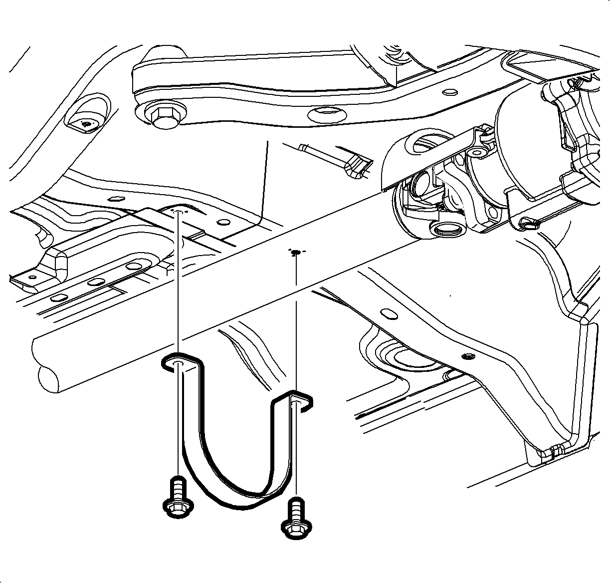
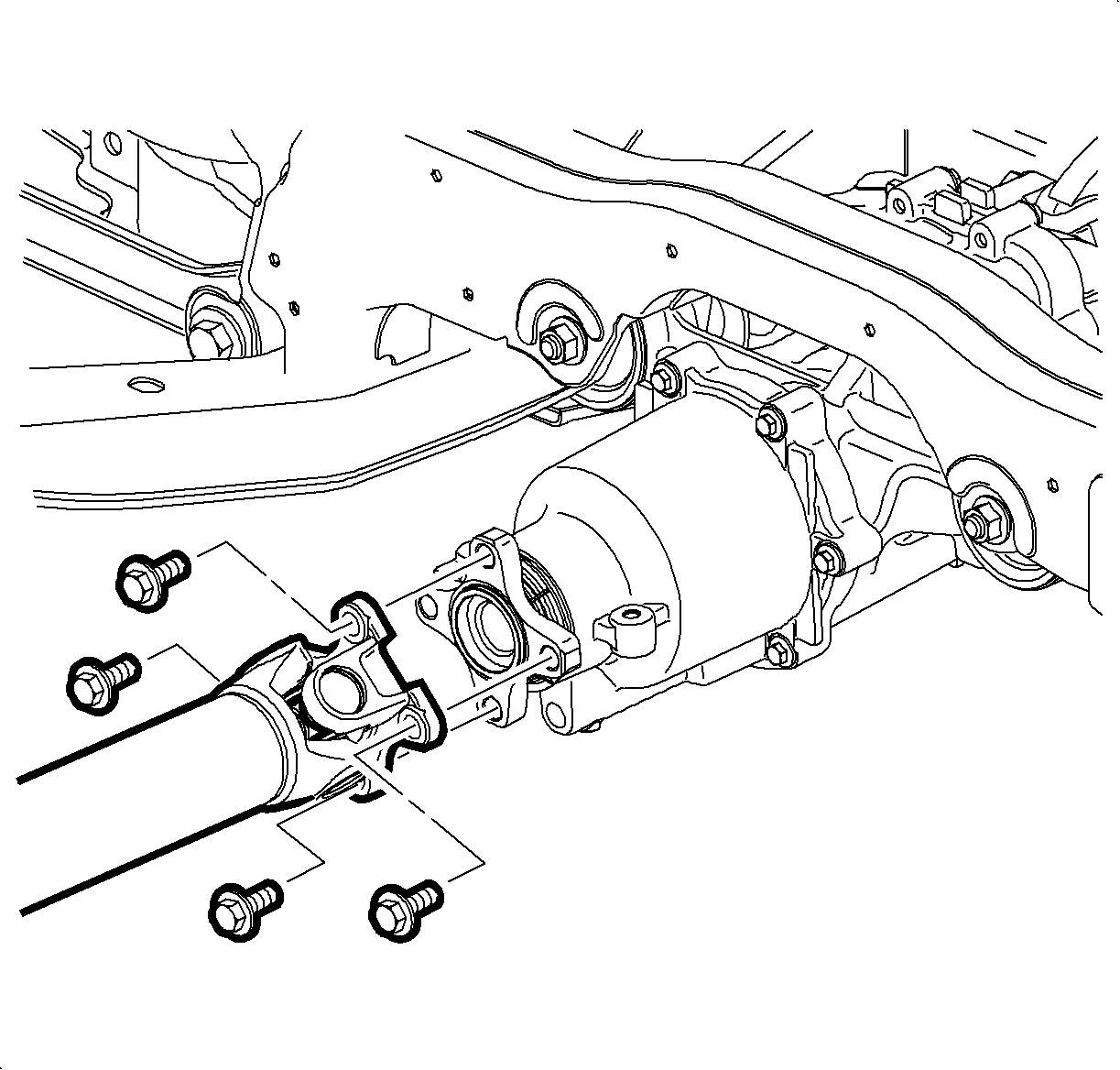
- Remove propeller shaft underbody guard loop bolts.
- Remove the guard loop.
- Reference mark the propeller shaft flange-to-pinion relationship at the rear drive module (RDM).
- Remove the propeller shaft flange mounting bolts at the RDM pinion flange.
- Apply forward pressure on the propeller shaft to disengage the propeller shaft rear flange.
- Position the end of the propeller shaft away from the RDM and secure it with a heavy mechanic’s wire or equivalent.
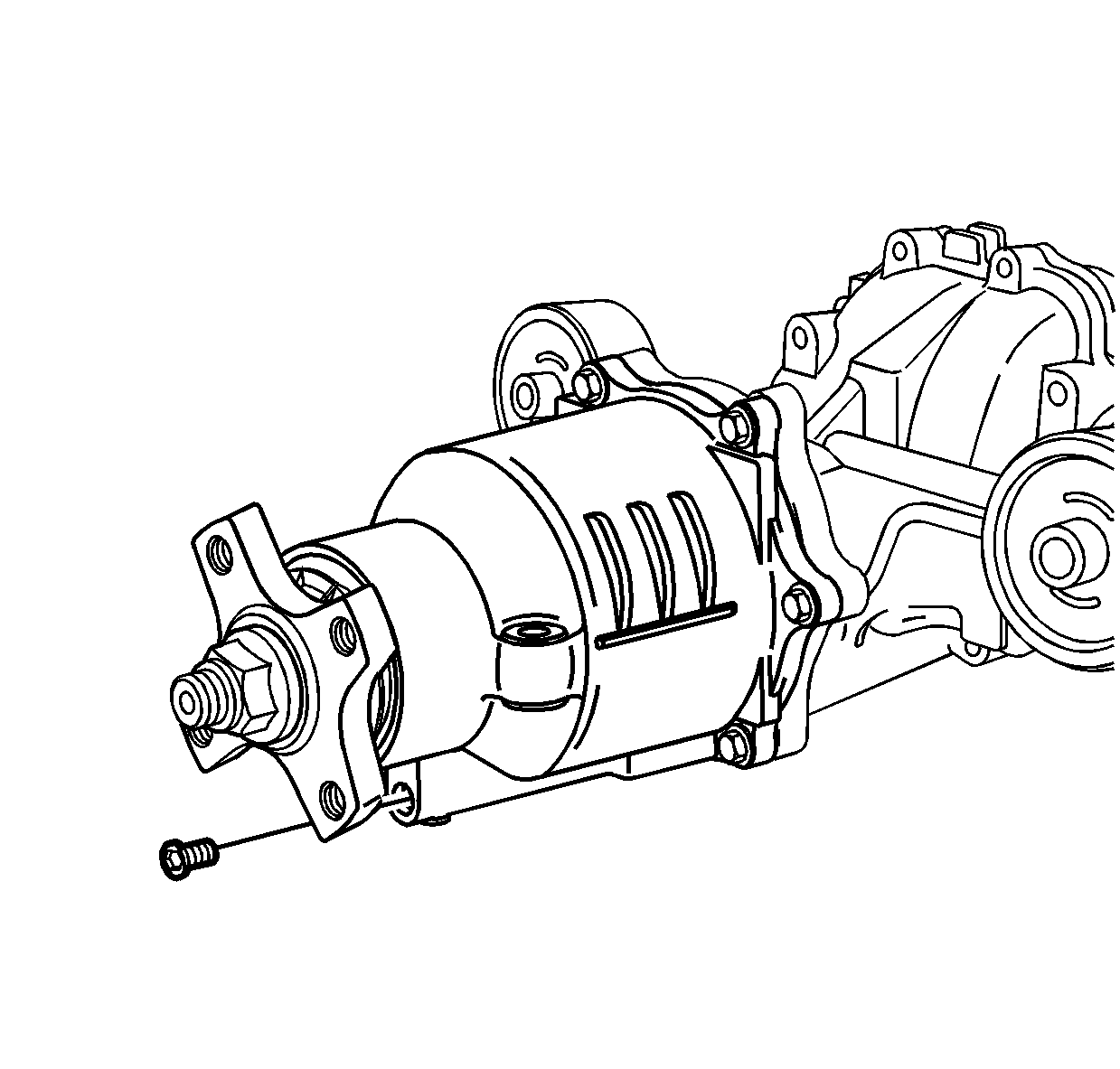
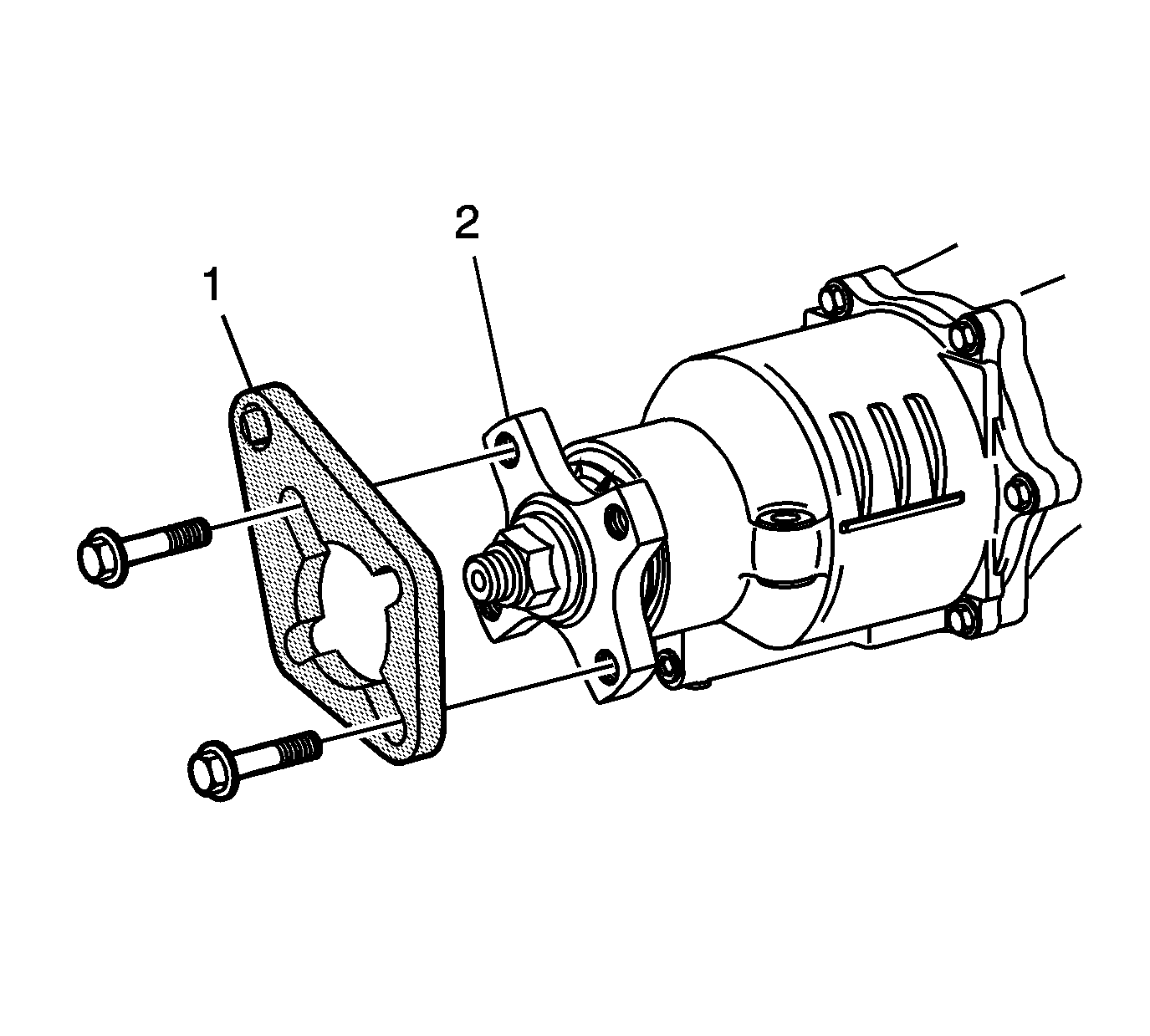
- Install pinion flange holder J44873 (1) to the pinion flange (2) using two propeller shaft bolts.
- Using a half-inch breaker bar to hold pinion flange holder J44873 stationary, loosen the pinion flange nut.
- Remove Pinion Flange Holder J44873.
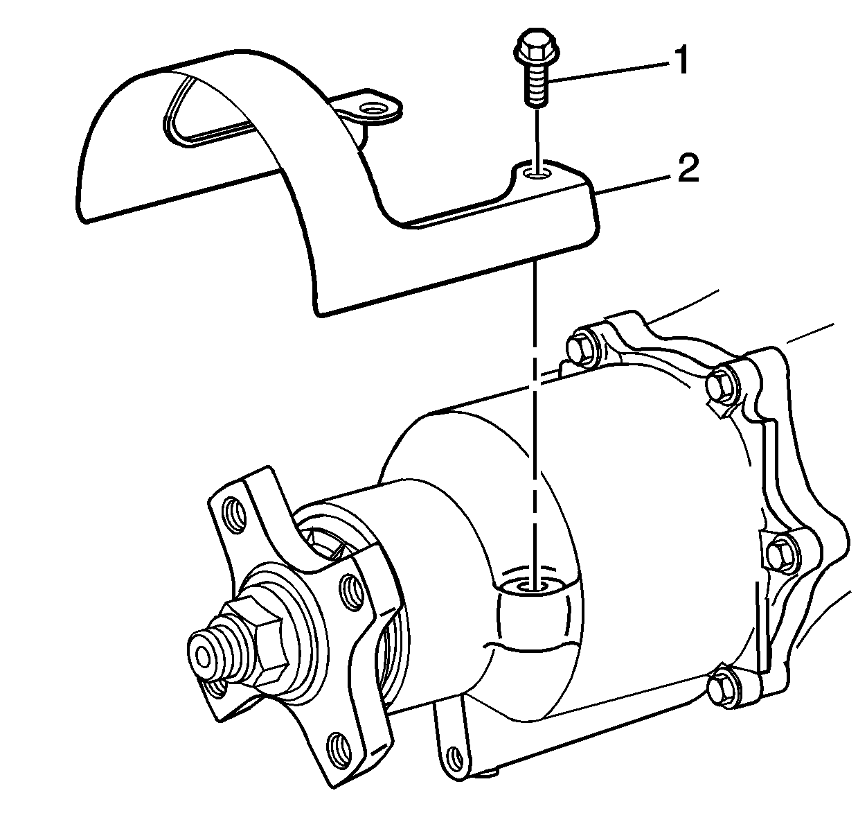
- Remove propeller shaft guard to rear drive module bolts and remove guard.
- Place a drain pan under the RDM to capture residual RDM fluid when separating RDM housing cover from RDM housing.
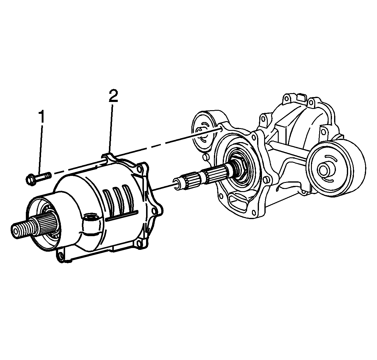
- Remove the RDM housing cover bolts (1) from RDM housing.
- Separate the RDM housing cover from the RDM housing.
- Carefully remove the RDM housing cover and drum from RDM housing.
- Remove and discard the pinion flange nut (1).
- Remove the pinion flange (2).
- Remove the clutch drum (2) from the RDM housing cover (1).
- Remove and discard the RDM filter assembly.
- Remove all traces of sealer from RDM housing and clutch cover sealing surfaces.
- Clean the RDM housing sealing surfaces with denatured alcohol or equivalent and dry with a clean, lint-free cloth.
Caution: Make sure vehicle is properly supported and squarely positioned on the hoist. To avoid any vehicle damage, serious personal injury or death when a vehicle is on a hoist, provide additional support for the vehicle at the opposite end from which components are being removed. This will reduce the possibility of the vehicle falling off the hoist.
Caution: To avoid any vehicle damage, serious personal injury or death, always use the jackstands to support the vehicle when lifting the vehicle with a jack.
Notice: Perform the following steps before
starting any vehicle lifting or jacking procedure:
• Remove or secure all of the vehicle's contents in order to avoid any shifting
or any movement that may occur during the vehicle lifting or jacking procedure. • The lifting or jacking equipment weight rating must meet or exceed the
weight of the vehicle and any vehicle contents. • The lifting or jacking equipment must meet the operational standards of
the lifting or jacking equipment's manufacturer. • Perform the vehicle lifting or jacking procedure on a clean, hard, dry,
level surface. • Perform the vehicle lifting or jacking procedure only at the identified
lift points. DO NOT allow the lifting or jacking equipment to contact any other vehicle
components.
Important: Place jackstands ONLY under strong and stable vehicle structures.
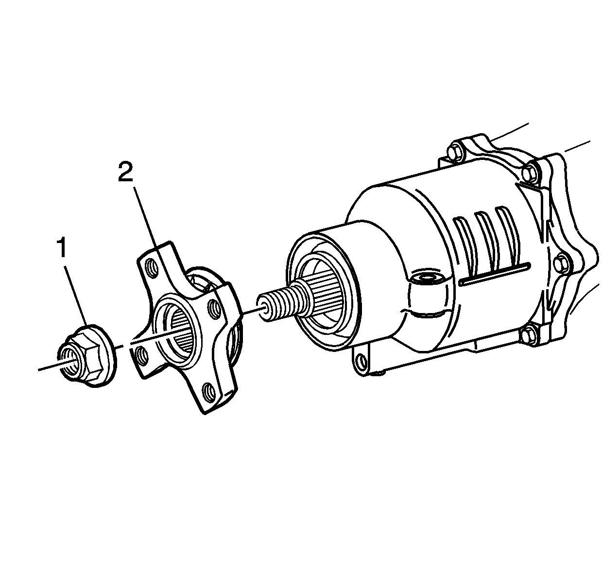
Notice: Discard used nut. If the old nut is used, it may loosen over time.
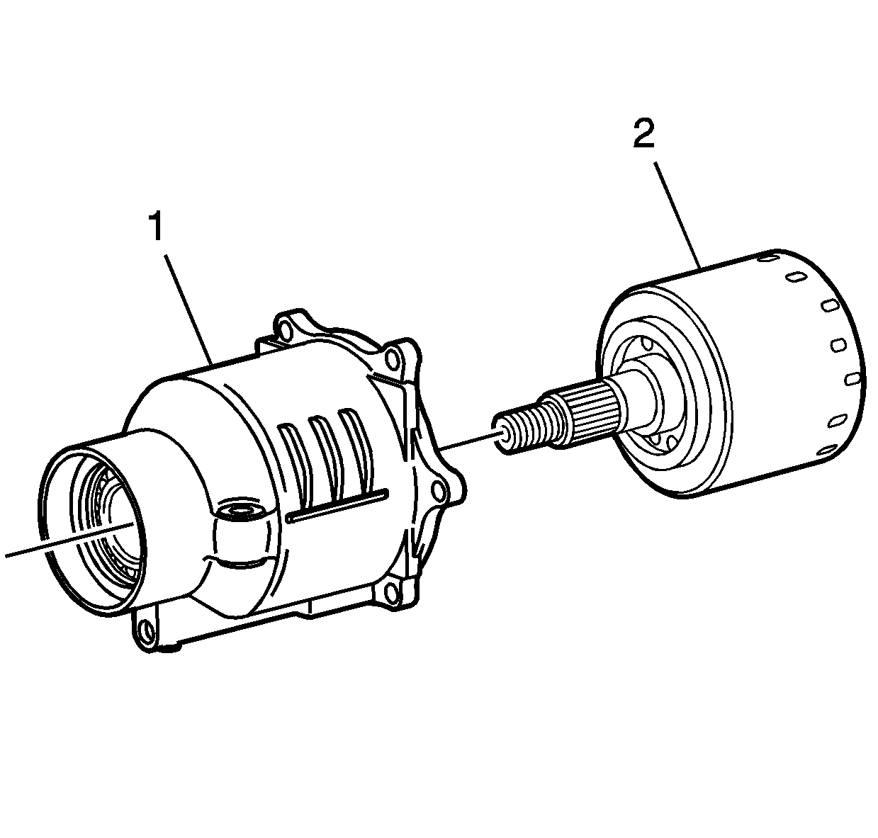
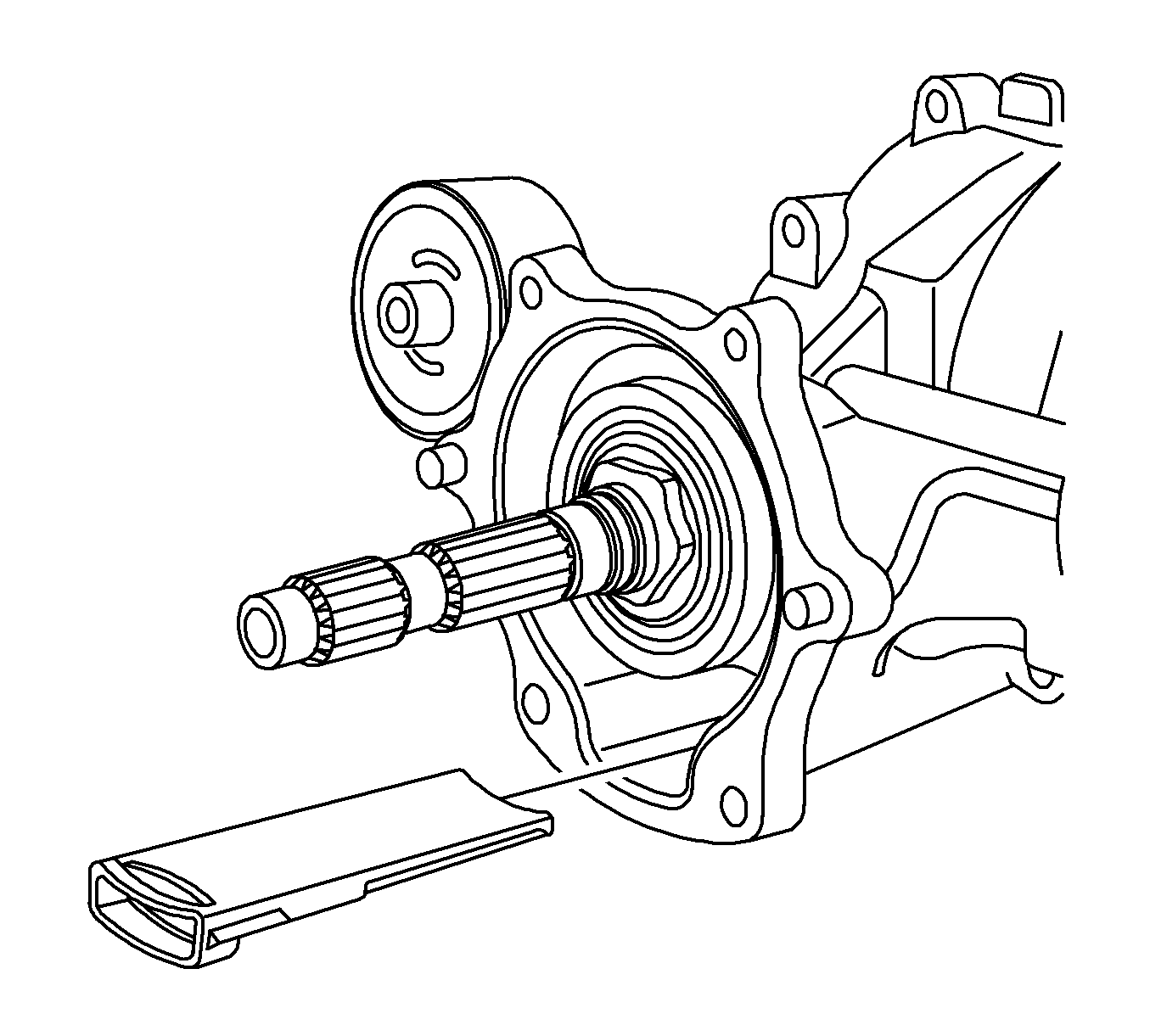
Notice: Do not gouge housing cover or RDM sealing surfaces. Do not use any kind of motored device for cleaning. If the sealing surfaces are damaged, leaks may result.
Notice: All sealant must be removed from RDM housing and clutch cover sealing surfaces to reduce the potential of a leak or excess sealant damaging RDM.
Installation Procedure
- Apply a continuous bead of sealer (Saturn P/N 21019581) of equal height and width to the RDM clutch housing sealing surface. Allow sealant to "skin" for 5 minutes before assembly.
- Install a NEW RDM filter assembly (P/N 12569934).
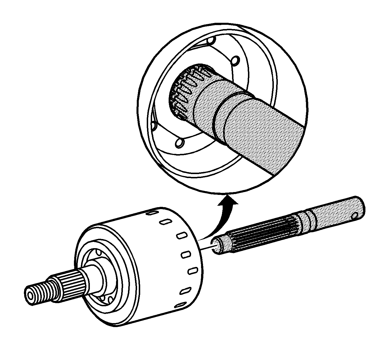
- Align the RDM clutch with the pump and pump bushing using alignment tool J46607. Place the alignment tool J46607 in the splines of the clutch. Twist alignment tool back and forth to align the pump and bushing. With a properly aligned clutch, the groove on the alignment tool J46607 will be flush with the drum as shown. Remove the alignment tool by pulling straight out.
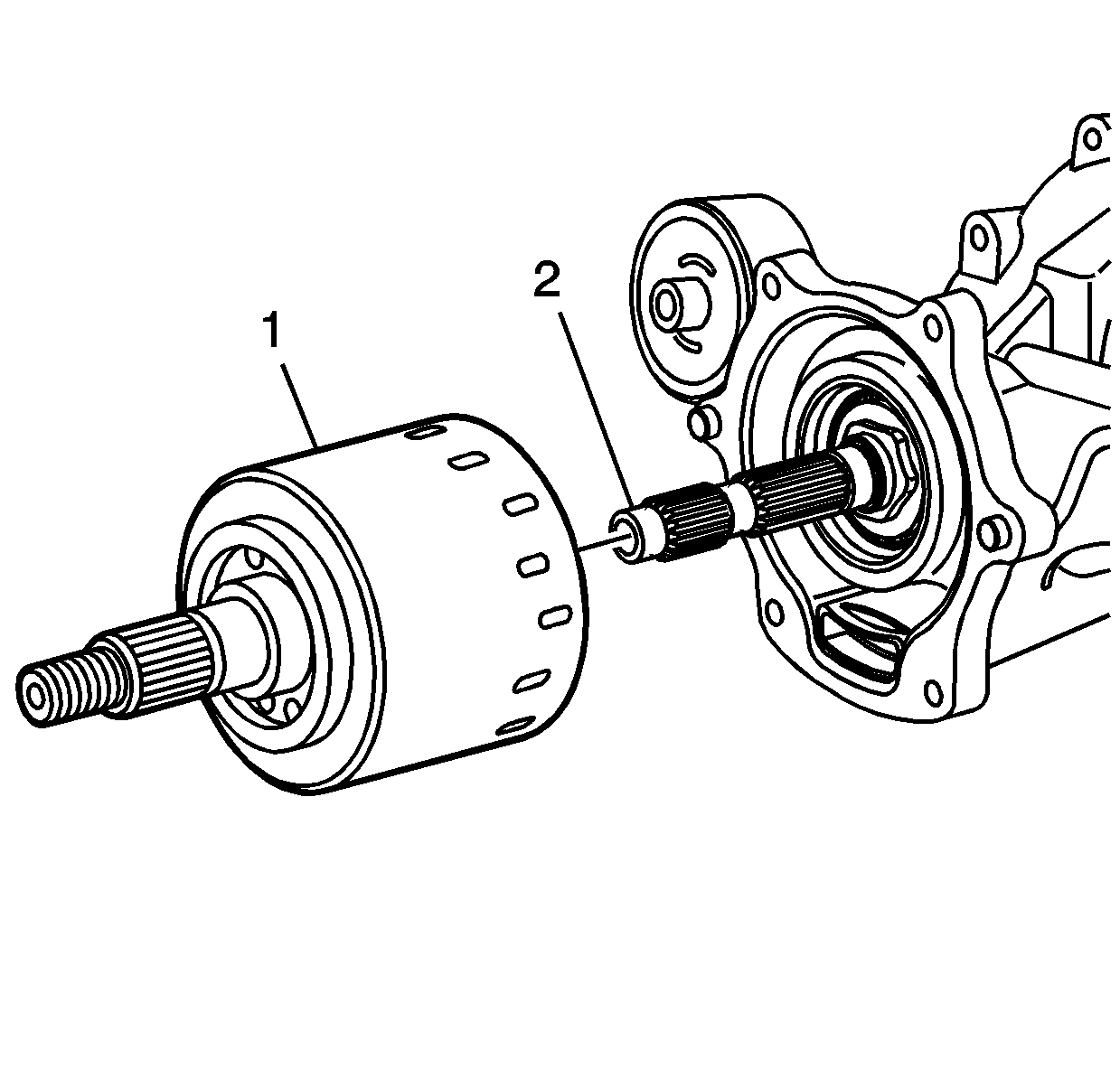
- Install the NEW clutch drum (1) (P/N 15235314) onto the pinion shaft (2).
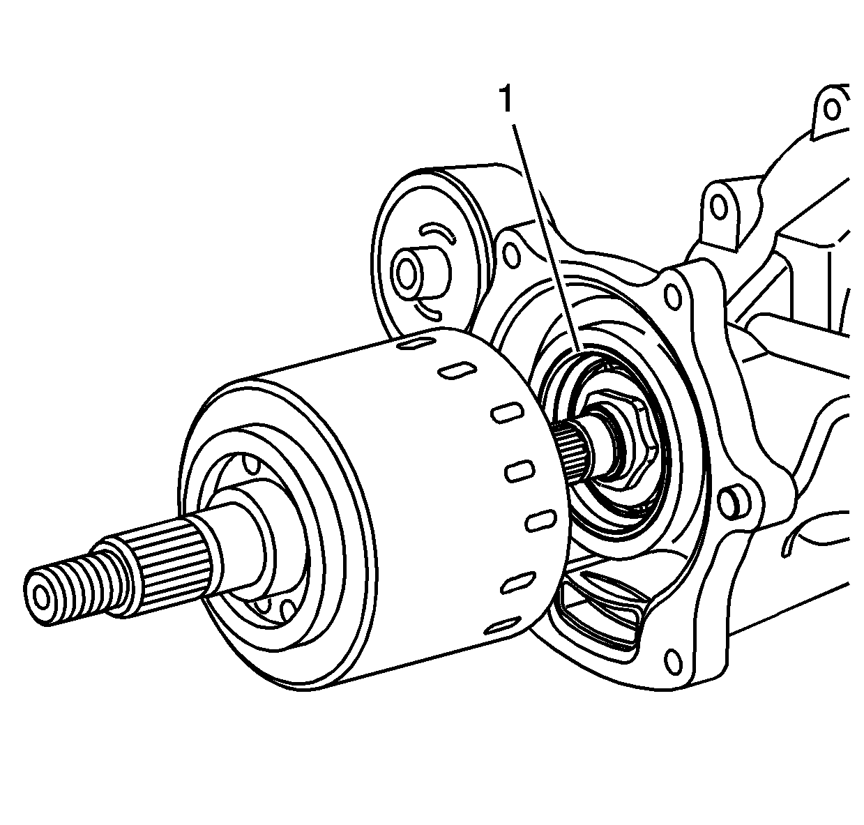
- When properly engaged, the RDM clutch drum will be fully seated against the clutch drum oil seal.
- Hand install the RDM clutch housing cover (1) and bolts (2) to the RDM differential housing, and then tighten bolts.
- Install propeller shaft guard (2) to RDM housing and tighten bolts (1).
- Install the pinion flange (2) to the RDM clutch shaft.
- Hand install a NEW input flange nut (1) to the RDM clutch shaft.
- Install pinion flange holder J44873 (1) to the pinion flange (2) using two propeller shaft bolts.
- Hold pinion flange with half-inch breaker bar to tighten nut.
- Thoroughly clean the drain plug threads and apply thread sealer Loctite® Threadlocker 592 (U.S.A.: P/N 21485278; Canada: P/N 10953480) or equivalent to plug threads.
- Install the drain plug to the RDM housing and tighten.
- Thoroughly clean and apply thread sealer Loctite® Threadlocker 262 (U.S.A.: P/N 21005994; Canada: P/N10953488) to the propeller shaft flange mounting bolt threads.
- Align the reference marks on the propeller shaft flange and the RDM input flange.
- Install the propeller shaft flange mounting bolts.
- Install the propeller shaft underbody guard loop.
- Install the propeller shaft underbody guard loop bolts.
- Remove RDM fill plug
- Fill the RDM with 750 ml (25.4 oz) of GM Versatrak® fluid (U.S.A.: P/N 12378514; Canada: P/N 88901045).
- Temporarily re-install RDM fill plug.
- Prime new RDM clutch using the following on-hoist priming method.
- Remove the RDM fill plug.
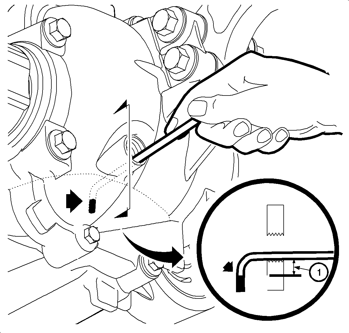
- Fabricate a dipstick using a length of heavy mechanic’s wire or equivalent. Position a 90 degree bend approximately 25 mm (1 in) from the end of the wire.
- Place the angled end of the dipstick into the fluid fill plug opening.
- Rest the wire squarely on the threads of the fill plug hole.
- Remove the dipstick and measure the distance between the bend and the fluid level as indicated by the witness mark (1).
- Adjust the fluid level as required by adding or removing fluid (P/N 12378514).
- Thoroughly clean the fill plug threads and apply thread sealer Loctite® Threadlocker 592 (U.S.A.: P/N 21485278; Canada: P/N 10953480) or equivalent to the threads of the RDM fill plug.
- Install the RDM fill plug.
- Lower the vehicle.
- Perform road test to check for leaks.
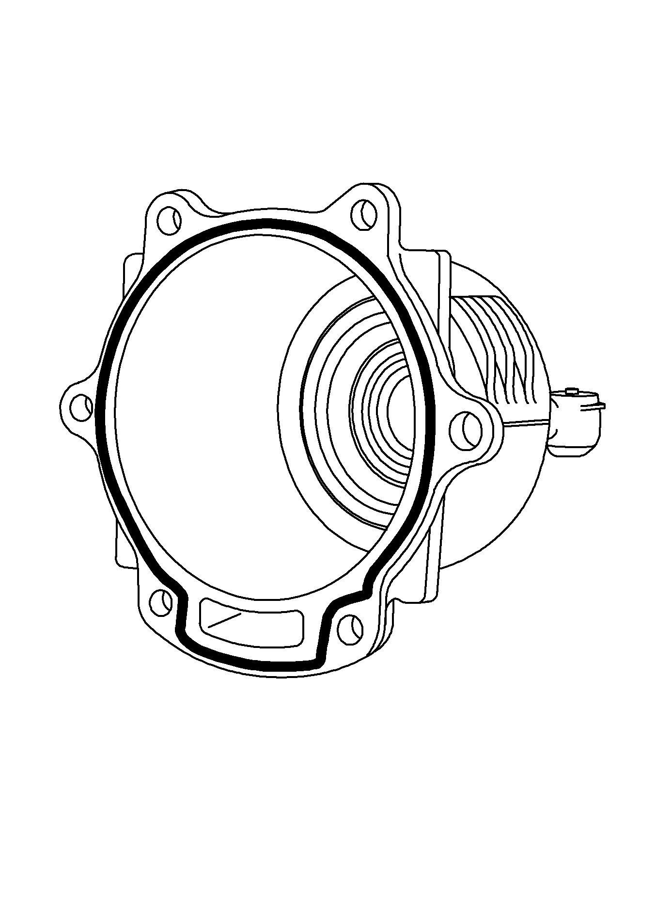
Important: Strict adherence to the sealer cure time must be observed.
Specification
Apply sealer to a height and width of 2.5 mm
(0.098 in.)

Notice: Do not submerge the clutch drum in solvent. This will damage friction material and gerotor pump.
Important: The clutch drum may require some slight rotational movement to install completely. If the clutch is not fully seated, the clutch housing may break when tightening bolts.
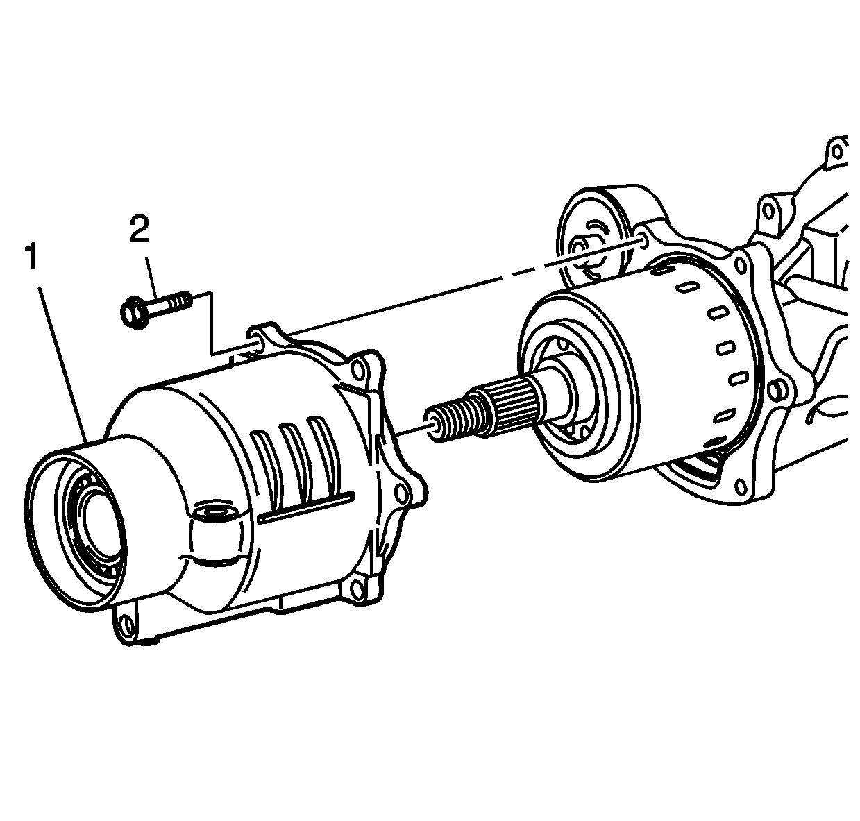
Notice: The clutch cover housing must be fully seated to the rear drive module (RDM). Do NOT use the mounting bolts to draw the cover to the RDM. If the cover does not fully seat to the RDM, the clutch drum assembly splines must be realigned to the pinion shaft splines before proceeding. Failure to follow these instructions will result in damage to the clutch assembly.
Important: Do not disturb the sealer bead applied to the RDM clutch housing when installing to RDM differential housing.
Tighten
Tighten Clutch Cover Bolts to 25 N·m
(19 ft-lbs).

Tighten
Tighten Propeller Shaft Guard-to-Rear Drive Module
Bolts to 23 N·m (17 ft-lbs).


Tighten
Tighten Pinion Shaft Nut to 203 N·m
(150 ft-lbs).

Tighten
Tighten Drain Plug to 30 N·m (22 ft-lbs).

Tighten
Tighten Propeller Shaft Rear Flange-to-Rear Drive
Module Bolts 50 N·m (37 ft-lbs).

Tighten
Tighten Underbody Guard Loop Bolts to 24 N·m
(18 ft-lbs).
| 22.1. | Ensure all wheels are off the ground. |
| 22.2. | Start the engine and place the transaxle in a forward gear. |
| 22.3. | Release the brake pedal. All four wheels will spin. |
| 22.4. | Slowly apply parking brake just enough to stop the rear wheels from rotating. |
| 22.5. | Carefully accelerate the engine until the rear wheels begin to rotate. |
| Notice: Do not exceed 5 seconds of park brake apply while the vehicle is in gear and the engine is running to avoid overheating the rear drive module. |
| 22.6. | Continue allowing the rear wheels to rotate for a maximum of 5 seconds. |
| 22.7. | Release parking brake and release the accelerator pedal. |
| 22.8. | Apply the brakes and bring the wheels to a stop. |
| 22.9. | Place the transaxle in park and turn the engine off. |
Specification
The distance between the bend and fluid level
should be 8-17 mm (0.32-0.68 in).
Notice: Too much or too little fluid may have an adverse affect on the operation of the all-wheel drive system.
Tighten
Tighten Rear Differential Assembly Fill Plug to
35 N·m (26 ft-lbs).
Credit
1. To receive credit, submit a claim with the information below:
Repair Performed | Parts Allow | Sale Type | Case Type | Labor Op | Labor Hours* | Admin. Hrs.**** |
|---|---|---|---|---|---|---|
Replace RDM Clutch Drum | * | WC | VC | V1267 | 1.7 | 0.1 |
* The parts allowance should be the sum total of the current SSPO Retailer net price plus 40% of all parts required for the repair. **** Administrative allowance. | ||||||
Claiming Loctite® Threadlocker 592, Loctite® Threadlocker 262 and Sealant - Right Stuff
It will be necessary to sell these materials to the CSO as "material" using net item code "M". per the chart on page 4 of this bulletin. Claims received in the amount of $9.59 will be accepted. Claims exceeding the amount of $9.59 will be returned with Return Reason 143 - material/reimbursement > maximum allowed.
2. To receive credit for loaner/rental vehicle costs incurred while owner awaits program repair, submit a claim with the information below:
Repair Performed | Sale Type | Case Type | Labor Op | Net Item Amount | Net Item Code | # Days Rental |
|---|---|---|---|---|---|---|
Loaner/Rental Reimbursement | WC | VC | V1268 | ** | C | *** |
** Net amount must be submitted as a miscellaneous sale...Loaner/rental reimbursement not to exceed $35/day *** Enter number of days vehicle was rented...Not to exceed 1 day. The completed Loaner/Rental Worksheet must be attached to the hard copy of the Customer Service Order (CSO). | ||||||
3. Check your Saturn SERVICELINE.XL Claim Memorandum daily. Remember to code the claim as a WC sale type, and VC case type. Contact your field representative if you need assistance.
4. All labor operations claimed in this bulletin must be submitted on individual (unrelated) CSO lines. Refer to the Customer Service Order Preparation Manual for details on Bulletin Claim Submission.
04090 LOANER/RENTAL WORKSHEET
Complete this worksheet and attach it to the hard copy of the Customer Service Order (CSO) to document all loaner/rental reimbursement claims submitted to Saturn.
VIN #____________________
Vehicle Loaner/Rental Allowance Explanation: $_________
__________________________________________________________
__________________________________________________________
Repair Performed | Sale Type | Case Type | Labor Op | Net Item Code | # Days Rental |
|---|---|---|---|---|---|
Loaner/Rental Reimbursement | WC | VC | V1268 | C | * |
* Not to exceed $35/day for 1 day
December, 2004
Dear Saturn VUE owner:
In August 2004, Saturn sent letters to current owners of 2002, 2003 and 2004 model year Saturn VUE vehicles to announce a voluntary customer satisfaction program, 04067. In our correspondence we explained that our parts inventory was not sufficient to perform all replacements at that time. We stated we would contact you again once the necessary replacement parts became available.
Today, we are writing to inform you that our parts inventory is now sufficient. Therefore, we urge you to contact your Saturn Retailer to arrange a convenient service appointment.
The rear suspension lateral link assemblies of certain model year 2002-2004 Saturn VUE vehicles may deform if subjected to a handling maneuver similar to that performed in the National Highway Traffic Safety Administration’s (NHTSA’s) newly implemented Dynamic Maneuvering Test ("Fishhook" Test). Deformation of the lateral link could result in the tire and wheel tipping inward until the tire contacts the trailing arm. If the tire were to contact the trailing arm, tire rotation would be inhibited.
Additionally, we have learned that your vehicle may exhibit a condition where owners may notice a moan or vibration noise emanating from the rear of the vehicle when turning at low speeds (such as parking lot maneuvers and/or surfaces like snow and gravel).
What Saturn Will Do: Saturn retailers will replace the rear lateral link assemblies, check and adjust wheel alignment and increase front/rear cold tire inflation pressures. To prevent the moan and/or vibration condition, Saturn retailers will replace the differential clutch drum in the rear drive module (RDM) and replace the RDM filter. Both services will be performed at no cost to you.
What You Should Do: Contact your Saturn Retailer to arrange to have the services performed. It will take about 4 hours to perform both services, although some additional time may be required for paperwork and processing.
The enclosed reply card identifies your vehicle and will facilitate completion of the repairs when presented to your Saturn retail facility. If your address has changed, please provide the new information in the space provided. This will assist us in ensuring that all affected vehicles are corrected.
Your Retailer is prepared to perform this service promptly and with minimal inconvenience to you. However, if your car is provided to the Retailer on the agreed service date and the condition is not remedied on that date, or within a reasonable time, please contact the Saturn Customer Assistance Center at 1-800-972-8876, or for the hearing impaired, 1-800-833-6000. We will assist you and the Retailer in getting your car serviced.
We sincerely regret any inconvenience or concern this situation may cause you and want you to know that we will do our best, throughout your ownership experience, to ensure that your Saturn provides you many miles of enjoyable and safe driving.
Thank you again for being a valued member of the Saturn family.
Sincerely,
Saturn
04090 and 04067
REPLACEMENT OF REAR DRIVE MODULE (RDM) DIFFERENTIAL CLUTCH DRUM
2004 SATURN VEHICLES EQUIPPED WITH A 3.5L V6 (L66) ENGINE AND ALL-WHEEL DRIVE
ATTENTION: General Motors of Canada Ltd. Saturn Retailers
Condition
The Rear Drive Module (RDM) on some 2004 Saturn VUE vehicles equipped with a 3.5L V6 (L66) engine and all-wheel drive may exhibit a condition where the owner may notice a moan or vibration noise emanating from the rear of the vehicle when turning at low speeds (such as parking lot maneuvers and/or surfaces like snow and gravel).
Correction
Saturn retailers will replace the differential clutch drum in the rear drive module (RDM) and replace the RDM filter.
Vehicles Involved
Involved are certain 2004 model year Saturn VUE vehicles equipped with a 3.5L V6 (L66) engine and all-wheel drive built within these VIN breakpoints:
Year | Division | Model | From | Through |
|---|---|---|---|---|
2004 | Saturn | VUE | 4S800001 | 4S892254 |
Important: Retailers should confirm vehicle eligibility through GMVIS (GM Vehicle Inquiry System) before beginning recall repairs. [Not all vehicles within the above breakpoints may be involved.]
For retailers with involved vehicles, a Campaign Initiation Detail Report containing the complete Vehicle Identification Number, customer name and address data has been prepared, and is being furnished to involved retailers. Retailers that have no involved vehicles currently assigned, will not receive a Campaign Initiation Detail Report.
The Campaign Initiation Detail Report may contain customer names and addresses obtained from Motor Vehicle Registration Records. The use of such motor vehicle registration data for any purpose other than follow-up necessary to complete this recall is a violation of law in several states/provinces/countries. Accordingly, you are urged to limit the use of this report to the follow-up necessary to complete this recall.
Parts Information
Parts required to complete this recall are to be obtained from General Motors Service Parts Operations (GMSPO). Please refer to your "involved vehicles listing" before ordering parts. Normal orders should be placed on a DRO = Daily Replenishment Order. In an emergency situation, parts should be ordered on a CSO = Customer Special Order.
Part Number | Description | Qty/ Vehicle |
|---|---|---|
15235314 | Limited Slip Differential Drum | 1 |
12569934 | Differential Oil Filter | 1 |
10953488 | Loctite® Threadlocker 262 or Permatex 27200 | $3.10 per vehicle *Billed as Net Item |
12569951 | Differential Pinion Gear Nut | 1 |
10953472 | Sealant - Right Stuff/Loctite® 5900 | $1.23 Per vehicle **Billed as Net Item |
88901045 | Rear Axle Lubricant (GM Versatrak® Fluid) | 1.5 bottles |
10953480 | Loctite® Threadlocker 592 | $1.02 per vehicle ***Billed as Net Item |
*1 tube will service 3 vehicles. One tube $9.29/3 vehicles = $3.10 per vehicle.
**1 tube will service 10 vehicles. One tube $12.31/10 vehicles = $1.23 per vehicle.
*** 1 tube will service 10 vehicles. One tube $10.19/10 vehicles = $1.02 per vehicle.
Total Material Allowance is $5.35 per vehicle
Service Procedure
Removal Procedure
- Raise and support the vehicle. (Refer to illustration.)
- Place a container under the RDM housing.
- Remove the RDM drain plug and drain the fluid.
- Remove propeller shaft underbody guard loop bolts.
- Remove the guard loop.
- Reference mark the propeller shaft flange-to-pinion relationship at the rear drive module (RDM).
- Remove the propeller shaft flange mounting bolts at the RDM pinion flange.
- Apply forward pressure on the propeller shaft to disengage the propeller shaft rear flange.
- Position the end of the propeller shaft away from the RDM and secure it with a heavy mechanic’s wire or equivalent.
- Install pinion flange holder J44873 (1) to the pinion flange (2) using two propeller shaft bolts.
- Using a half-inch breaker bar to hold pinion flange holder J44873 stationary, loosen the pinion flange nut.
- Remove Pinion Flange Holder J44873.
- Remove propeller shaft guard to rear drive module bolts and remove guard.
- Place a drain pan under the RDM to capture residual RDM fluid when separating RDM housing cover from RDM housing.
- Remove the RDM housing cover bolts (1) from RDM housing.
- Separate the RDM housing cover from the RDM housing.
- Carefully remove the RDM housing cover and drum from RDM housing.
- Remove and discard the pinion flange nut (1).
- Remove the pinion flange (2).
- Remove the clutch drum (2) from the RDM housing cover (1).
- Remove and discard the RDM filter assembly.
- Remove all traces of sealer from RDM housing and clutch cover sealing surfaces.
- Clean the RDM housing sealing surfaces with denatured alcohol or equivalent and dry with a clean, lint-free cloth.
Caution: Make sure vehicle is properly supported and squarely positioned on the hoist. To avoid any vehicle damage, serious personal injury or death when a vehicle is on a hoist, provide additional support for the vehicle at the opposite end from which components are being removed. This will reduce the possibility of the vehicle falling off the hoist.
Caution: To avoid any vehicle damage, serious personal injury or death, always use the jackstands to support the vehicle when lifting the vehicle with a jack.
Notice: Perform the following steps before
starting any vehicle lifting or jacking procedure:
• Remove or secure all of the vehicle's contents in order to avoid any shifting
or any movement that may occur during the vehicle lifting or jacking procedure. • The lifting or jacking equipment weight rating must meet or exceed the
weight of the vehicle and any vehicle contents. • The lifting or jacking equipment must meet the operational standards of
the lifting or jacking equipment's manufacturer. • Perform the vehicle lifting or jacking procedure on a clean, hard, dry,
level surface. • Perform the vehicle lifting or jacking procedure only at the identified
lift points. DO NOT allow the lifting or jacking equipment to contact any other vehicle
components.
Important: Place jackstands ONLY under strong and stable vehicle structures.


Notice: Discard used nut. If the old nut is used, it may loosen over time.


Notice: Do not gouge housing cover or RDM sealing surfaces. Do not use any kind of motored device for cleaning. If the sealing surfaces are damaged, leaks may result.
Notice: All sealant must be removed from RDM housing and clutch cover sealing surfaces to reduce the potential of a leak or excess sealant damaging RDM.
Installation Procedure
- Apply a continuous bead of sealer (P/N 10953472) of equal height and width to the RDM clutch housing sealing surface. Allow sealant to "skin" for 5 minutes before assembly.
- Install a NEW RDM filter assembly (P/N 12569934).
- Align the RDM clutch with the pump and pump bushing using alignment tool J46607. Place the alignment tool J46607 in the splines of the clutch. Twist alignment tool back and forth to align the pump and bushing. With a properly aligned clutch, the groove on the alignment tool J46607 will be flush with the drum as shown. Remove the alignment tool by pulling straight out.
- Install the NEW clutch drum (1) (P/N 15235314) onto the pinion shaft (2).
- When properly engaged, the RDM clutch drum will be fully seated against the clutch drum oil seal.
- Hand install the RDM clutch housing cover (1) and bolts (2) to the RDM differential housing, and then tighten bolts.
- Install propeller shaft guard (2) to RDM housing and tighten bolts (1).
- Install the pinion flange (2) to the RDM clutch shaft.
- Hand install a NEW input flange nut (1) to the RDM clutch shaft.
- Install pinion flange holder J44873 (1) to the pinion flange (2) using two propeller shaft bolts.
- Hold pinion flange with half-inch breaker bar to tighten nut.
- Thoroughly clean the drain plug threads and apply thread sealer Loctite® Threadlocker 592 (P/N 10953480) or equivalent to plug threads.
- Install the drain plug to the RDM housing and tighten.
- Thoroughly clean and apply thread sealer Loctite® Threadlocker 262 (P/N 10953488) to the propeller shaft flange mounting bolt threads.
- Align the reference marks on the propeller shaft flange and the RDM input flange.
- Install the propeller shaft flange mounting bolts.
- Install the propeller shaft underbody guard loop.
- Install the propeller shaft underbody guard loop bolts.
- Remove RDM fill plug
- Fill the RDM with 750 ml (25.4 oz) of GM Versatrak® fluid (P/N 88901045).
- Temporarily re-install RDM fill plug.
- Prime new RDM clutch using the following on-hoist priming method.
- Remove the RDM fill plug.
- Fabricate a dipstick using a length of heavy mechanic’s wire or equivalent. Position a 90 degree bend approximately 25 mm (1 in) from the end of the wire.
- Place the angled end of the dipstick into the fluid fill plug opening.
- Rest the wire squarely on the threads of the fill plug hole.
- Remove the dipstick and measure the distance between the bend and the fluid level as indicated by the witness mark (1).
- Adjust the fluid level as required by adding or removing fluid (P/N 88901045).
- Thoroughly clean the fill plug threads and apply thread sealer Loctite® Threadlocker 592 (P/N 10953480) or equivalent to the threads of the RDM fill plug.
- Install the RDM fill plug.
- Lower the vehicle.
- Perform road test to check for leaks.

Important: Strict adherence to the sealer cure time must be observed.
Specification
Apply sealer to a height and width of 2.5 mm
(0.098 in.)


Notice: Do not submerge the clutch drum in solvent. This will damage friction material and gerotor pump.
Important: The clutch drum may require some slight rotational movement to install completely. If the clutch is not fully seated, the clutch housing may break when tightening bolts.


Notice: The clutch cover housing must be fully seated to the rear drive module (RDM). Do NOT use the mounting bolts to draw the cover to the RDM. If the cover does not fully seat to the RDM, the clutch drum assembly splines must be realigned to the pinion shaft splines before proceeding. Failure to follow these instructions will result in damage to the clutch assembly.
Important: Do not disturb the sealer bead applied to the RDM clutch housing when installing to RDM differential housing.
Tighten
Tighten Clutch Cover Bolts to 25 N·m
(19 ft-lbs).

Tighten
Tighten Propeller Shaft Guard-to-Rear Drive Module
Bolts to 23 N·m (17 ft-lbs).


Tighten
Tighten Pinion Shaft Nut to 203 N·m
(150 ft-lbs).

Tighten
Tighten Drain Plug to 30 N·m (22 ft-lbs).

Tighten
Tighten Propeller Shaft Rear Flange-to-Rear Drive
Module Bolts 50 N·m (37 ft-lbs).

Tighten
Tighten Underbody Guard Loop Bolts to 24 N·m
(18 ft-lbs).

| 22.1. | Ensure all wheels are off the ground. |
| 22.2. | Start the engine and place the transaxle in a forward gear. |
| 22.3. | Release the brake pedal. All four wheels will spin. |
| 22.4. | Slowly apply parking brake just enough to stop the rear wheels from rotating. |
| 22.5. | Carefully accelerate the engine until the rear wheels begin to rotate. |
| Notice: Do not exceed 5 seconds of park brake apply while the vehicle is in gear and the engine is running to avoid overheating the rear drive module. |
| 22.6. | Continue allowing the rear wheels to rotate for a maximum of 5 seconds. |
| 22.7. | Release parking brake and release the accelerator pedal. |
| 22.8. | Apply the brakes and bring the wheels to a stop. |
| 22.9. | Place the transaxle in park and turn the engine off. |

Specification
The distance between the bend and fluid level
should be 8-17 mm (0.32-0.68 in).
Notice: Too much or too little fluid may have an adverse affect on the operation of the all-wheel drive system.
Tighten
Tighten Rear Differential Assembly Fill Plug to
35 N·m (26 ft-lbs).
Claim Information
Submit a Product Recall Claim with the information indicated below:
REPAIR PERFORMED | PART COUNT | PART NO. | PARTS ALLOW | CC-FC | LABOUR OP | LABOUR HOURS* | NET ITEM |
|---|---|---|---|---|---|---|---|
Replace RDM Clutch Drum | -- | -- | ** | MA-96 | V1267 | 1.7 | 0.1 |
* For Recall Administrative Allowance, add 0.1 hours to the "Labour Hours."
** The "Parts Allowance" should be the sum total of the current GMSPO Retailer Net price plus applicable mark-up for parts needed to complete the repair.
*** The amount identified in the "Net Item" column should represent the sum total of the current GMSPO Dealer net price plus applicable Mark-Up for Loctite® Threadlocker 262, Loctite® Threadlocker 592 and Sealant - Right Stuff/Loctite® 5900 needed to perform the required repairs, not to exceed $5.35 per vehicle.
Refer to the General Motors Claims Processing Manual for details on Product Recall Claim Submission.
Customer Notification
Customers will be notified of this recall on their vehicles by General Motors (see copy of customer letter included with this bulletin).
Retailer Recall Responsibility
All unsold new vehicles in Retailers' possession and subject to this recall must be held and inspected/repaired per the service procedure of this recall bulletin before customers take possession of these vehicles.
Retailers are to service all vehicles subject to this recall at no charge to customers, regardless of mileage, age of vehicle, or ownership, from this time forward.
Customers who have recently purchased vehicles sold from your vehicle inventory, and for which there is no customer information indicated on the Retailer listing, are to be contacted by the Retailer. Arrangements are to be made to make the required correction according to the instructions contained in this bulletin. This could be done by mailing to such customers a copy of the customer letter accompanying this bulletin. Recall follow-up cards should not be used for this purpose, since the customer may not as yet have received the notification letter.
In summary, whenever a vehicle subject to this recall enters your vehicle inventory, or is in your retail facility for service in the future, you must take the steps necessary to be sure the recall correction has been made before selling or releasing the vehicle.
December 2004Dear Saturn Owner::
We have learned that your vehicle may exhibit a condition where owners may notice a moan or vibration noise emanating from the rear of the vehicle when turning at low speeds (such as parking lot maneuvers and/or surfaces like snow and gravel).
Your Saturn retailer will replace the differential clutch drum in the rear drive module (RDM) and replace the RDM filter. This service will be performed for you at no charge.
You may be contacted by a Retailer other than the Retailer who sold or is currently servicing your vehicle. Please be advised that you may take your vehicle to the Saturn facility of your choice to have the recall service work completed. Please contact your Saturn Retailer as soon as possible to arrange a service date.
This letter identifies your vehicle. Presentation of this letter to your Retailer will assist their Service personnel in completing the necessary correction to your vehicle in the shortest possible time.
We are sorry to cause you this inconvenience; however, we have taken this action in the interest of your continued satisfaction with our products.
Customer Support Department
04090
/il
