Tools Required
| • | J 39400-A Halogen Leak Detector |
| • | SA9111E Hose Clamp Pliers |
Removal Procedure
- Disable the frontal and curtain air bags. Refer to SIR Disabling and Enabling , SIR Disabling and Enabling , SIR Disabling and Enabling , and SIR Disabling and Enabling in SIR.
- Recover the refrigerant. Refer to Refrigerant Recovery and Recharging .
- Drain the engine coolant. Refer to Cooling System Draining and Filling in Engine Cooling.
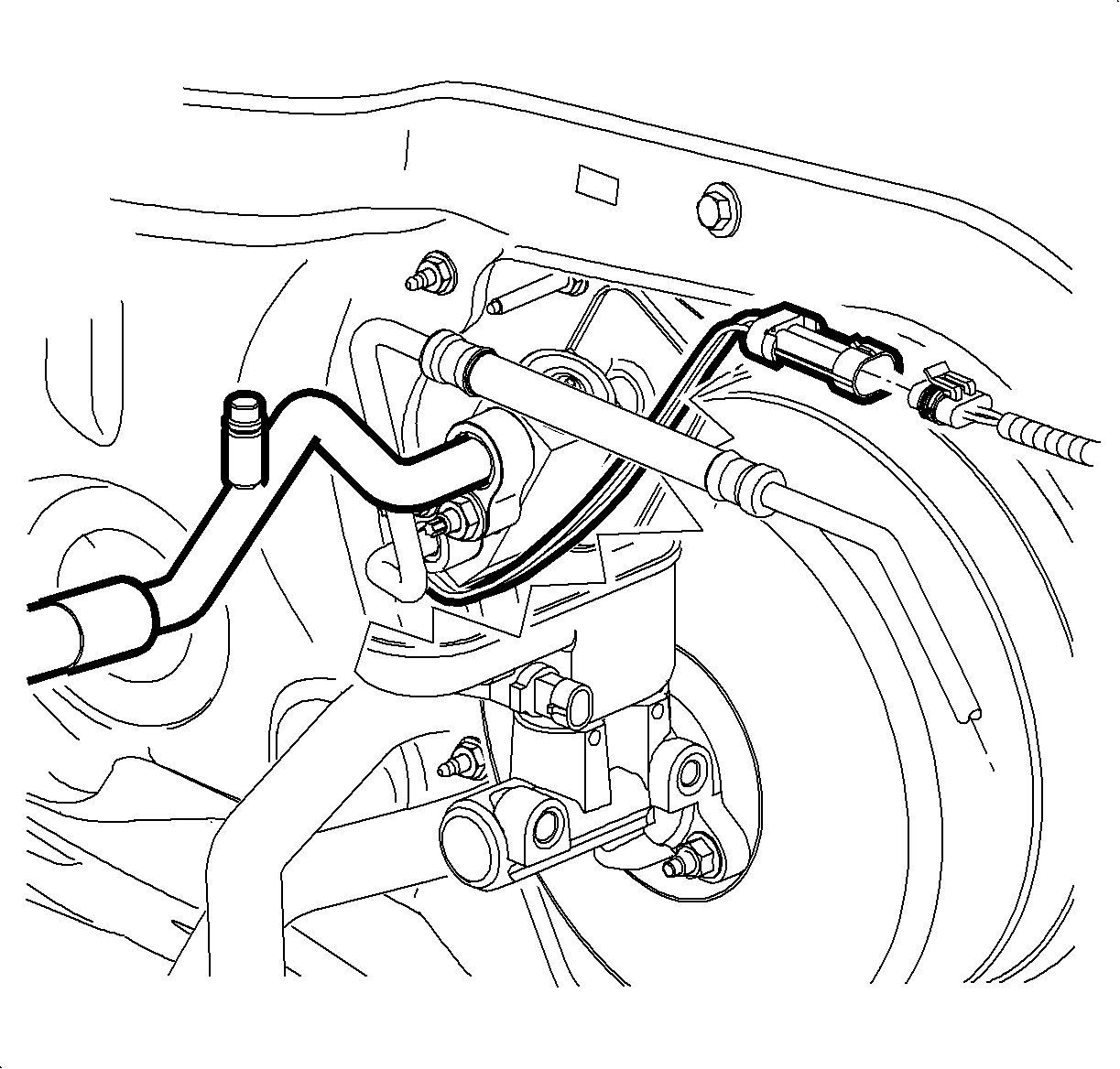
- Remove the evaporator outlet hose nut from the TXV.
- Remove the evaporator outlet hose from the TXV.
- Remove and discard the sealing washer from the evaporator outlet hose. Refer to Sealing Washer Replacement .
- Install a protective cap to the evaporator outlet hose to prevent contamination and desiccant saturation.
- Remove the liquid line nut from the TXV.
- Remove the liquid line from the TXV.
- Remove and discard the sealing washer from the liquid line. Refer to Sealing Washer Replacement .
- Install a protective cap to the liquid line to prevent contamination and desiccant saturation.
- Disconnect the TXV low temperature sensor connector from the engine harness.
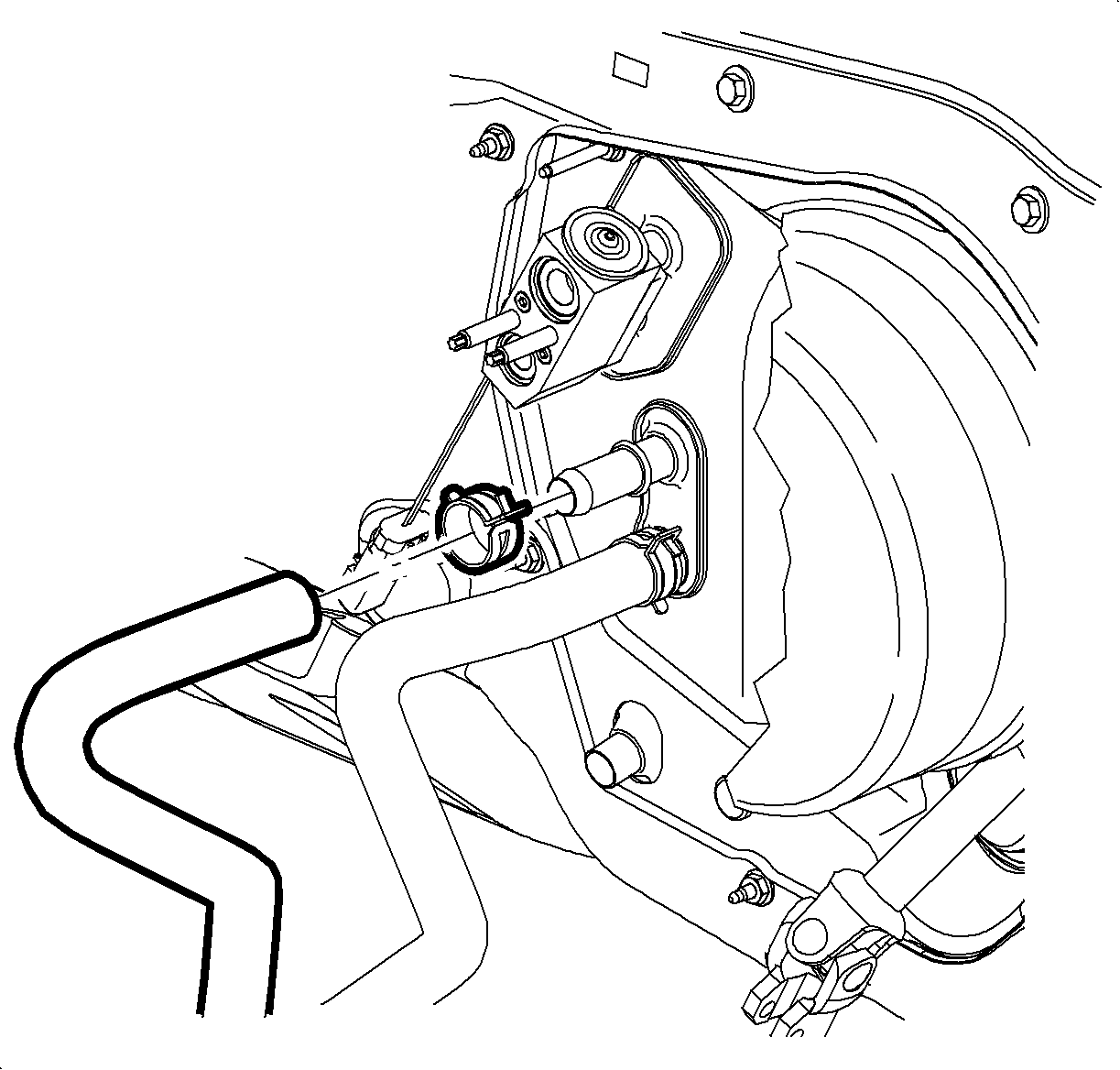
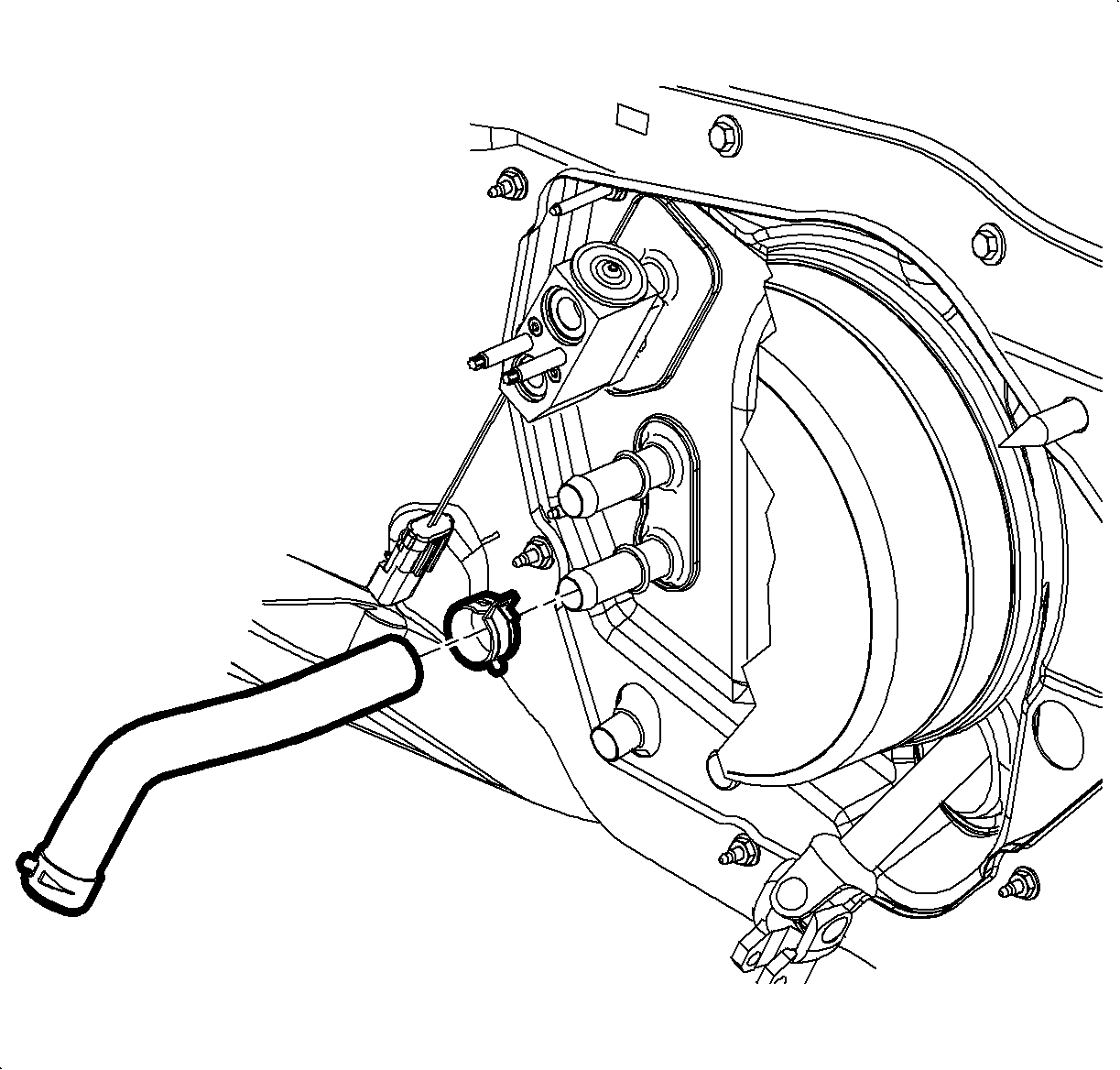
- Reposition the heater outlet hose clamp at the heater core using SA9111E .
- Remove the heater outlet hose from the heater core.
- Reposition the heater inlet hose clamp at the heater core using SA9111E .
- Remove the heater inlet hose at the heater core.
- Plug the heater core and the evaporator core with clean towels to prevent spillage when the HVAC module is removed.
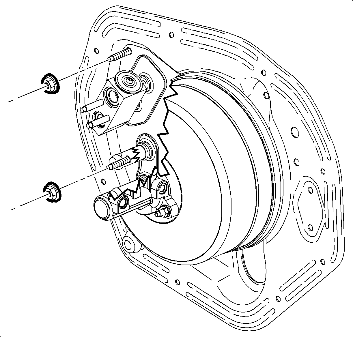
- Remove the HVAC module seal nuts from the front of dash.
- Remove the instrument panel (I/P) retainer. Refer to Instrument Panel Retainer Replacement in Instrument Panel, Gages, and Console.
- Remove the shift control bracket. Refer to Transmission Control Replacement in Manual Transmission -- Getrag 5 or Transmission Control Replacement in Automatic Transmission -- VT25-E.
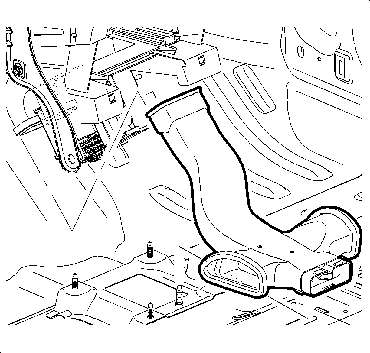
- Remove the center floor air outlet duct by sliding the duct forward then up at the rear.
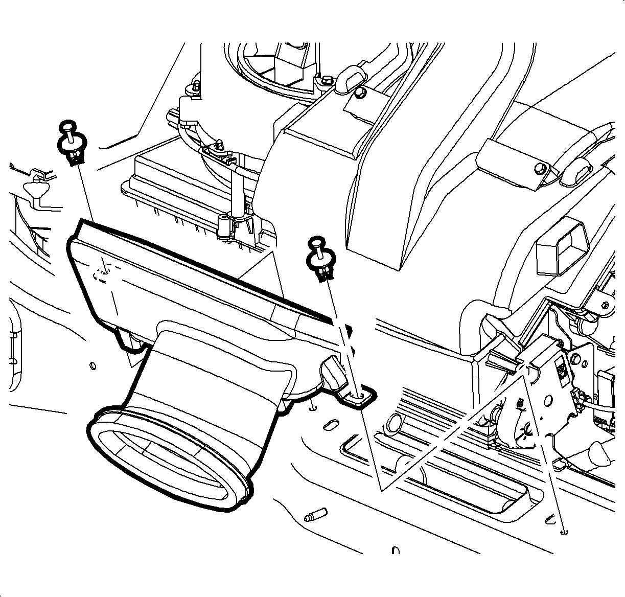
- Remove the center I/P air outlet duct retainers from the cross car beam.
- Remove the center I/P air outlet duct from the cross car beam.
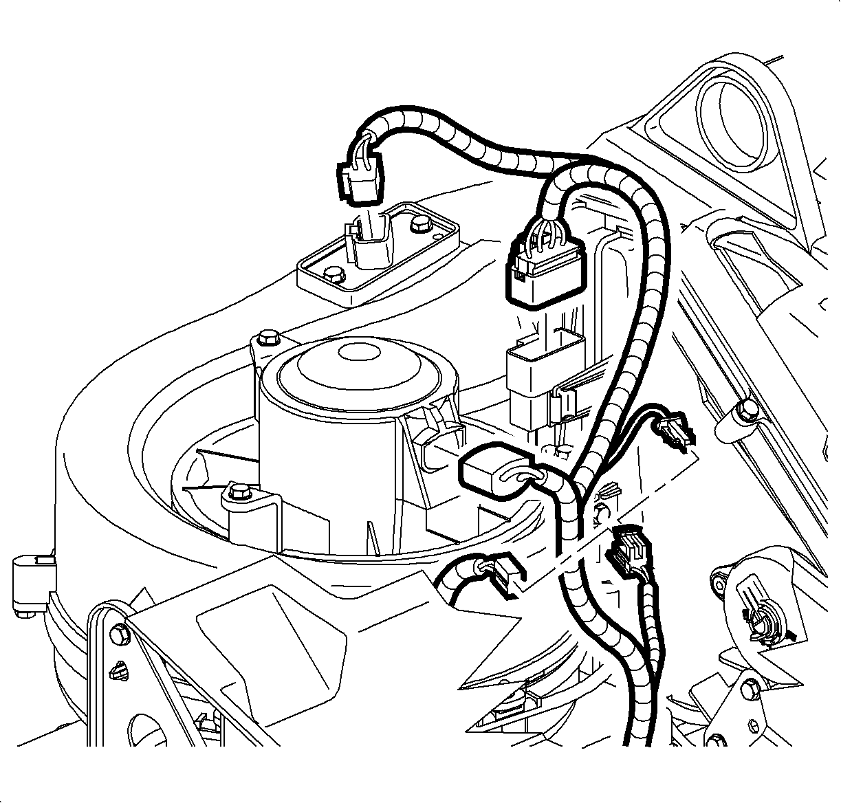
- Disconnect the blower motor electrical connector from the I/P wire harness.
- Disconnect the blower motor resistor electrical connector from the I/P wire harness.
- Disconnect the HVAC module electrical connector from the I/P wire harness.
- Remove the defroster duct retainer from the cross car beam.
- Remove the defroster duct nuts from the HVAC module.
- Remove the defroster duct from the HVAC module.
- Disconnect the I/P wire harness clips from the HVAC module.
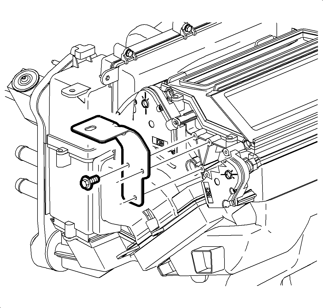
- Remove the metal bracket nut from the cross car beam.
- Remove the metal bracket nuts from the HVAC module.
- Remove the metal bracket from the HVAC module.
- Remove the HVAC module bolts from the right side of the cross car beam.
- Remove the HVAC module nut from the center of the cross car beam.
- Remove HVAC module bolt from the left side of the cross car beam.
- Remove the HVAC module from the vehicle.



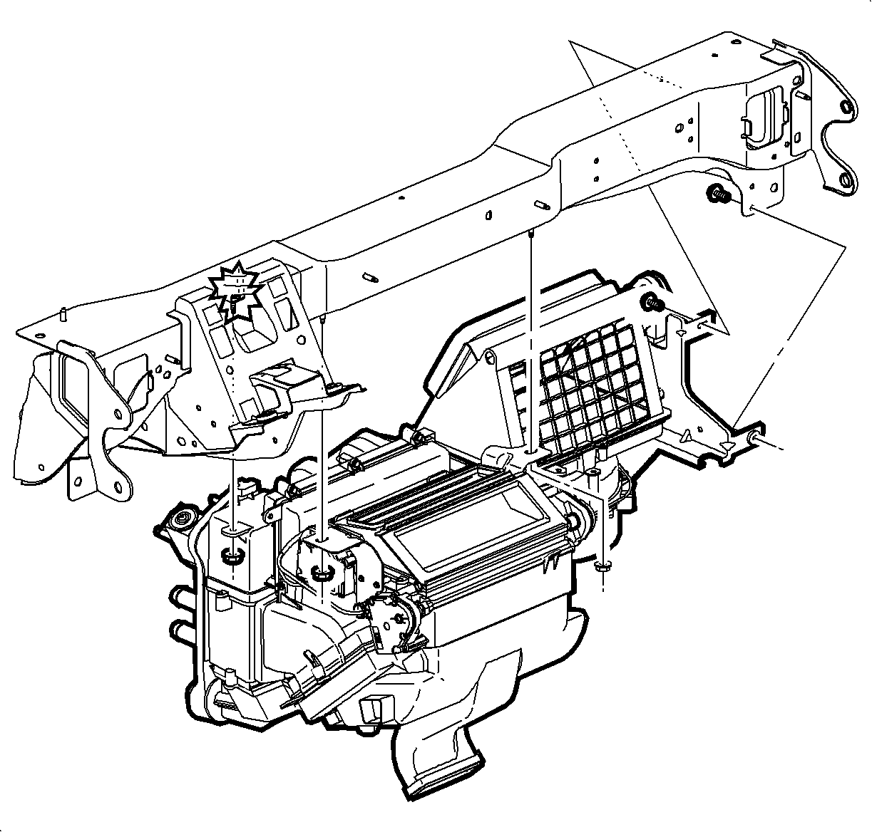
Installation Procedure
- Inspect the front of dash seal for proper alignment.
- Inspect the seal mating surfaces to ensure there are no obstructions.
- Loose hang the HVAC module from the cross car beam.
- Install the metal bracket to the left side of the HVAC module.
- Install the metal bracket bolts to the left side of the HVAC module.
- Install the HVAC module seal nuts to the front of dash. Draw the HVAC module to the front of dash evenly by alternating between the seal nuts.
- Install the HVAC module bolts to the right side of the cross car beam.
- Push up on the right side of the HVAC module while tightening the HVAC module bolts to the cross car beam.
- Install the HVAC module bolt to the left side of the cross car beam.
- Install the HVAC module nuts to the left side and center of the cross car beam.
- Install the defroster duct to the HVAC module.
- Install the defroster duct nuts to the HVAC module.
- Install the defroster duct retainer to the cross car beam.
- Connect the I/P wire harness clips to the HVAC module.
- Connect the blower motor electrical connector to the I/P wire harness.
- Connect the blower motor resistor electrical connector to the I/P wire harness.
- Connect the HVAC module electrical connector to the I/P wire harness.
- Install the center I/P duct to the cross car beam.
- Install the center I/P duct retainers to the cross car beam.
- Install the center floor air outlet by sliding forward onto the front floor air outlet then down and rearward over the rear floor air outlet.
- Install the shift control bracket. Refer to Transmission Control Replacement in Manual Transmission -- Getrag 5 or Transmission Control Replacement in Automatic Transmission -- VT25-E.
- Install the I/P retainer. Refer to Instrument Panel Retainer Replacement in Instrument Panel, Gages, and Console.
- Install the heater inlet hose to the heater core.
- Install the heater inlet hose clamp to the heater core using SA9111E .
- Install the heater outlet hose to heater core outlet.
- Install the heater outlet hose clamp to the heater core usingSA9111E .
- Ensure the mating surfaces are clean and free of debris, and install a new seal washer to the liquid line. Refer to Sealing Washer Replacement .
- Install the liquid line to the TXV.
- Install the liquid line nut to the TXV.
- Ensure the mating surfaces are clean and free of debris, and install a new seal washer to the evaporator outlet hose. Refer to Sealing Washer Replacement .
- Install the evaporator outlet hose to the TXV.
- Install the evaporator outlet hose nut to the TXV.
- Enable the frontal and curtain air bags. Refer to SIR Disabling and Enabling , SIR Disabling and Enabling , SIR Disabling and Enabling , and SIR Disabling and Enabling in SIR.
- Fill the coolant. Refer to Cooling System Draining and Filling in Engine Cooling.
- Evacuate and charge the A/C system. Refer to Refrigerant Recovery and Recharging .
- Test the affected A/C joints for leaks using J 39400-A .

Important: Make sure the HVAC module seals are flush and even as they meet their mating surfaces. This will reduce the chance of leaks and ensure proper fit.
Important: Make sure the plastic molded in bracket at the center of the HVAC module is forward of the cross car beam during installation.

Notice: Use the correct fastener in the correct location. Replacement fasteners must be the correct part number for that application. Fasteners requiring replacement or fasteners requiring the use of thread locking compound or sealant are identified in the service procedure. Do not use paints, lubricants, or corrosion inhibitors on fasteners or fastener joint surfaces unless specified. These coatings affect fastener torque and joint clamping force and may damage the fastener. Use the correct tightening sequence and specifications when installing fasteners in order to avoid damage to parts and systems.
Tighten
Tighten the bolts to 2 N·m (18 lb in).

Important: New front of dash seal nuts must be used to prevent leaks.
Tighten
Tighten the nuts to 8 N·m (71 lb in).

Tighten
Tighten the bolts to 8 N·m (71 lb in).
Tighten
Tighten the bolt to 8 N·m (71 lb in).
Tighten
Tighten the nuts to 8 N·m (71 lb in).

Tighten
Tighten the nuts to 2.5 N·m (22 lb in).


Tighten
Tighten the nut to 16 N·m (12 lb ft).

Tighten
Tighten the nut to 16 N·m (12 lb ft).
