Air Conditioning Evaporator Thermal Expansion Valve Replacement First Design
Tools Required
J 39400-A Halogen Leak Detector
Removal Procedure
- Recover the refrigerant. Refer to Refrigerant Recovery and Recharging .
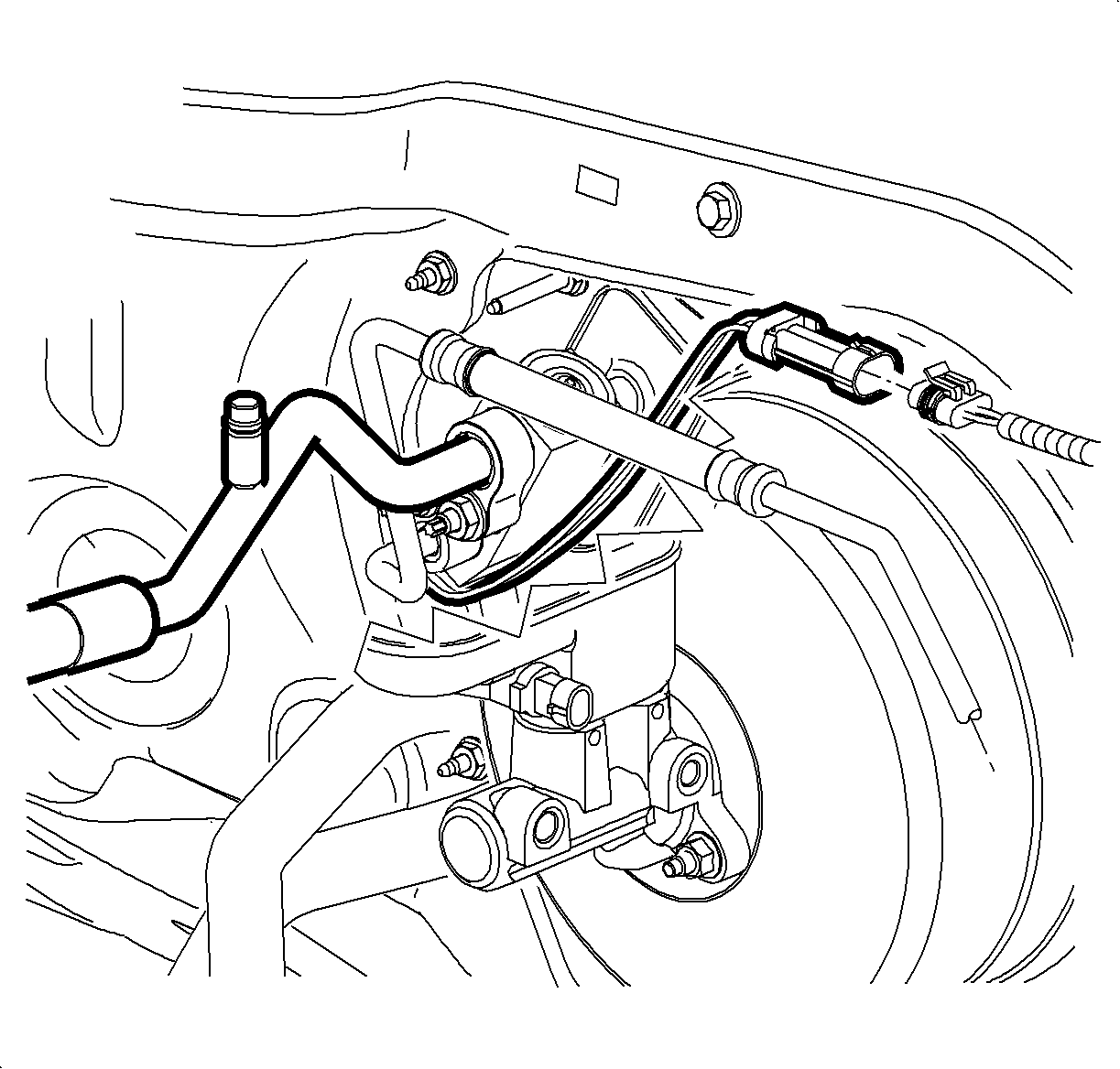
- Remove the evaporator outlet hose nut from the TXV.
- Remove the evaporator outlet hose from the TXV.
- Install a protective cap to the evaporator outlet hose to prevent contamination and desiccant saturation.
- Remove the liquid line nut from the TXV.
- Remove the liquid line from the TXV.
- Install a protective cap to the liquid line to prevent contamination and desiccant saturation.
- Disconnect the refrigerant low temperature sensor from the engine harness.
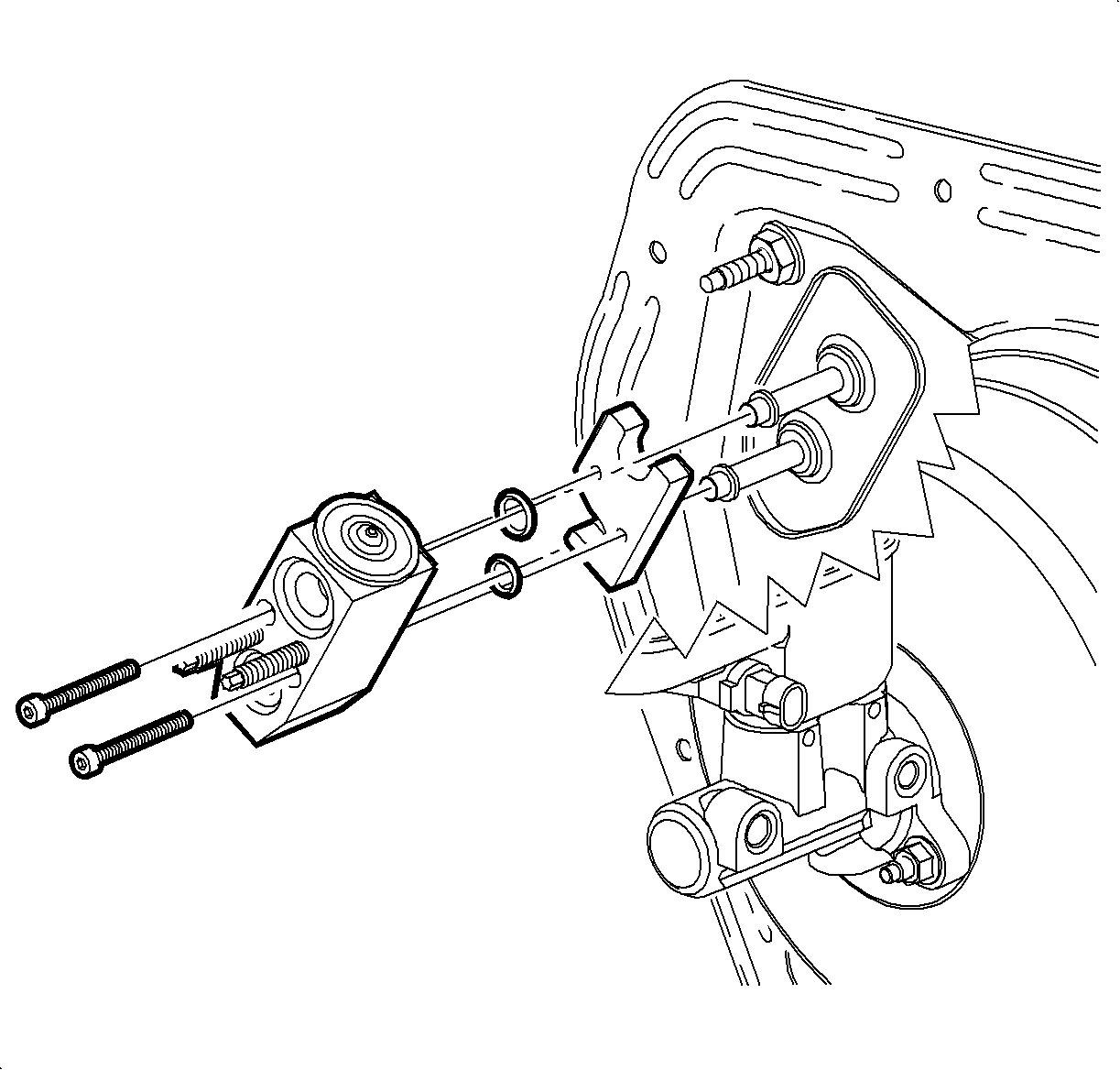
- Remove the TXV bolts from the backing plate.
- Remove the TXV and the backing plate from the vehicle.
- Remove and discard the O-rings from the evaporator pipes. Refer to O-Ring Replacement .
- Install a protective cap to the evaporator pipes to prevent contamination and desiccant saturation.

Important: When removing the thermal expansion valve (TXV), keep dirt and foreign material from getting on or into the O-ring sealing surfaces. Clean tools and a clean work area are important for proper service. The TXV seal area should be cleaned before any repairs are performed. The parts must be kept clean at all times and any parts to be assembled should be cleaned with a non-petroleum based solvent and dried with air. Use only lint free cloths to wipe parts. Do not allow solvent to enter evaporator or hoses.

Installation Procedure
- Remove the protective caps from the evaporator pipe and ensure the seal areas are clean, dry and lint free.
- Install new O-rings to the evaporator pipes. Refer to O-Ring Replacement .
- Remove the protective caps from the TXV.
- Install the TXV and the backing plate to the evaporator pipes.
- Install the TXV bolts to the backing plate.
- Remove the protective cap from the liquid line.
- Install a new seal washer to the liquid line. Refer to Sealing Washer Replacement .
- Install the liquid line to the TXV.
- Install the liquid line nut to the TXV.
- Remove the protective cap from the evaporator outlet hose.
- Install a new seal washer to the evaporator outlet hose. Refer to Sealing Washer Replacement .
- Install the evaporator outlet hose to the TXV.
- Install the evaporator outlet hose nut to the TXV.
- Connect the refrigerant low temperature sensor to the engine harness.
- Evacuate and charge the A/C system. Refer to Refrigerant Recovery and Recharging .
- Test the affected A/C joints for leaks using J 39400-A .

Important: Use only lint free cloths to wipe parts. Do not allow any solvent to enter evaporator or hoses.
Notice: Use the correct fastener in the correct location. Replacement fasteners must be the correct part number for that application. Fasteners requiring replacement or fasteners requiring the use of thread locking compound or sealant are identified in the service procedure. Do not use paints, lubricants, or corrosion inhibitors on fasteners or fastener joint surfaces unless specified. These coatings affect fastener torque and joint clamping force and may damage the fastener. Use the correct tightening sequence and specifications when installing fasteners in order to avoid damage to parts and systems.
Tighten
Tighten the bolts to 9 N·m (80 lb in).

Tighten
Tighten the nut to 16 N·m (12 lb ft).

Tighten
Tighten the nut to 16 N·m (12 lb ft).

Air Conditioning Evaporator Thermal Expansion Valve Replacement Second Design
Tools Required
J 39400-A Halogen Leak Detector
Removal Procedure
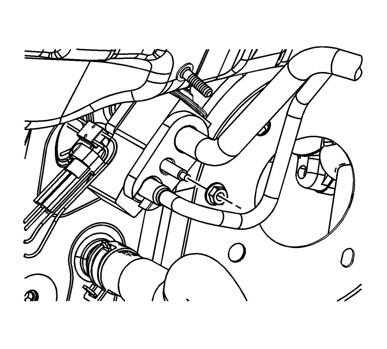
The second design can be identified by the attachment method of the evaporator outlet hose and the liquid line to the Thermal Expansion Valve (TXV) . They are retained to the TXV as a pair using a single nut.
- Recover the refrigerant. Refer to Refrigerant Recovery and Recharging .
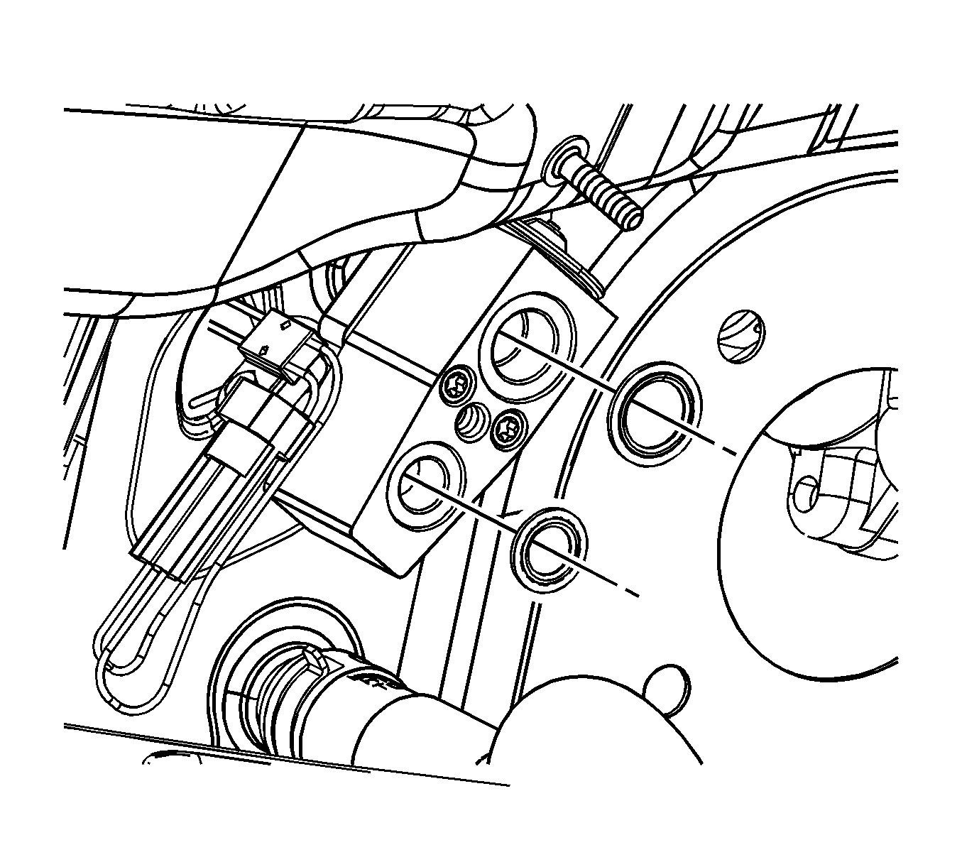
- Remove the evaporator outlet hose and liquid line retainer plate nut from the TXV.
- Remove the evaporator outlet hose and liquid line from the TXV.
- Remove and discard the sealing washers from the evaporator outlet hose and liquid line.
- Install protective caps to the evaporator outlet hose and the liquid line to prevent contamination and desiccant saturation.
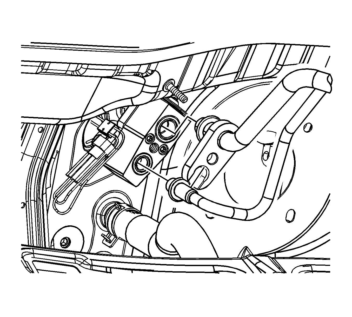
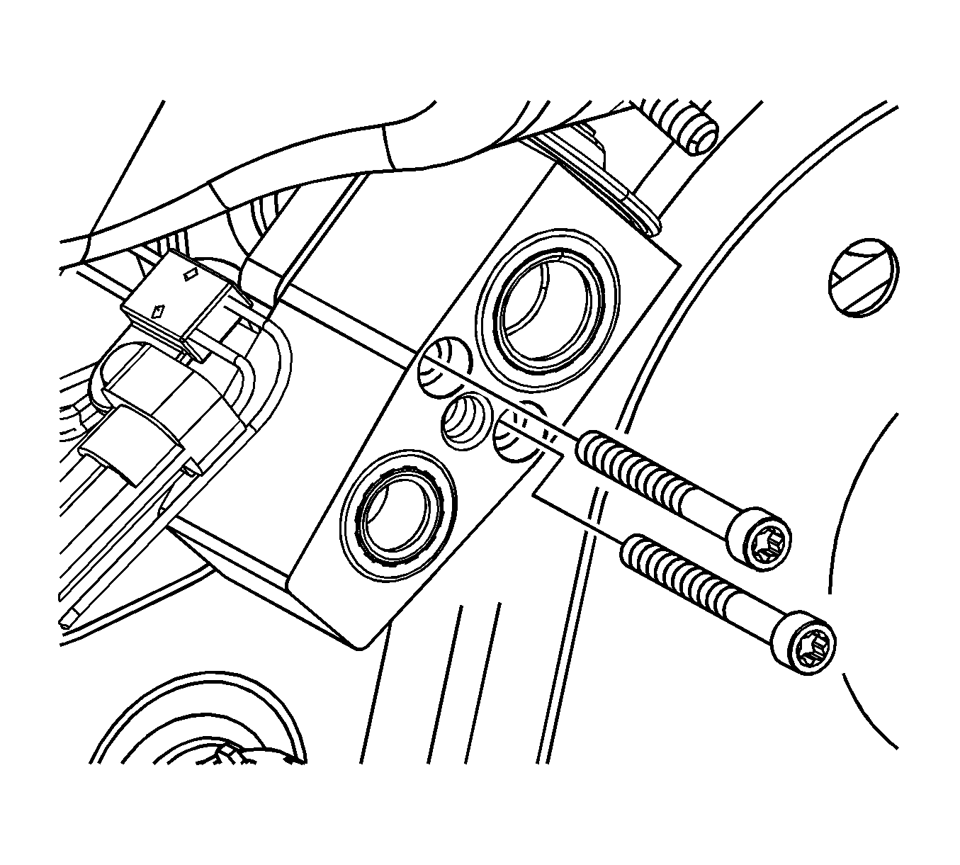
- Remove the TXV bolts from the backing plate.
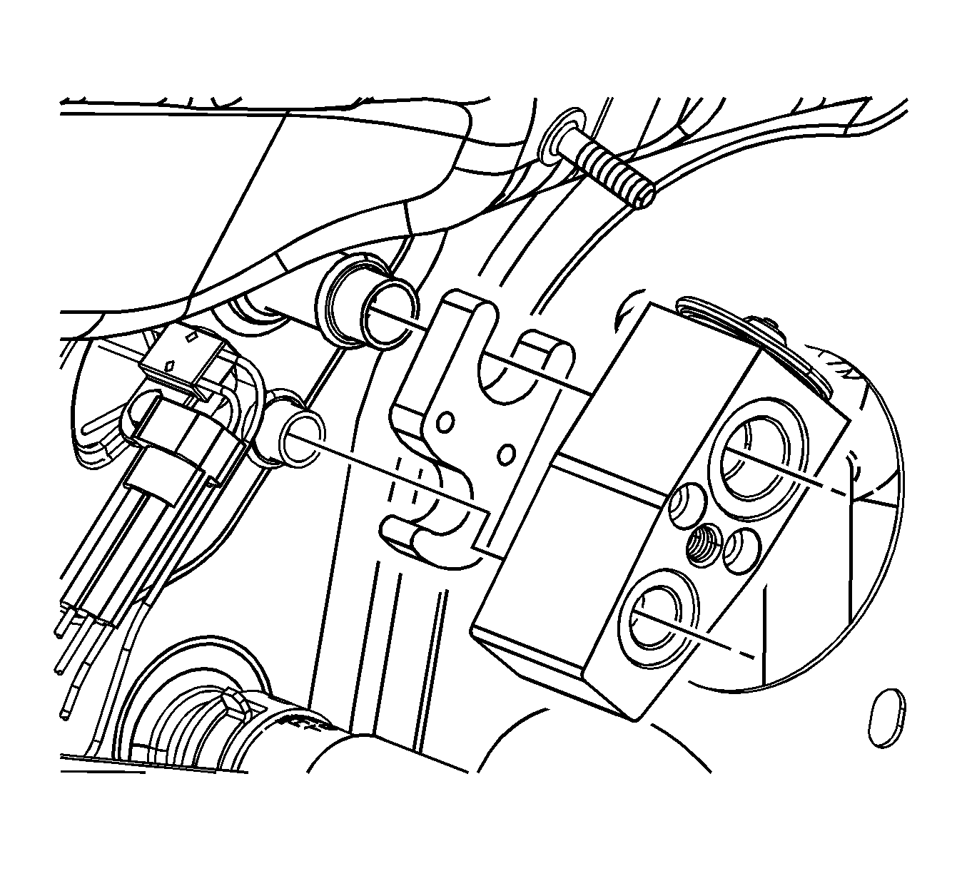
- Remove the TXV and the backing plate from the vehicle.
- Remove and discard the O-rings from the evaporator pipes. Refer to O-Ring Replacement .
- Install a protective cap to the evaporator pipes to prevent contamination and desiccant saturation.
Important: When removing the thermal expansion valve (TXV), keep dirt and foreign material from getting on or into the O-ring sealing surfaces. Clean tools and a clean work area are important for proper service. The TXV seal area should be cleaned before any repairs are performed. The parts must be kept clean at all times and any parts to be assembled should be cleaned with a non-petroleum based solvent and dried with air. Use only lint free cloths to wipe parts. Do not allow solvent to enter evaporator or hoses.
Installation Procedure
- Remove the protective caps from the evaporator pipe and ensure the seal areas are clean, dry and lint free.
- Install new O-rings to the evaporator pipes. Refer to O-Ring Replacement .
- Remove the protective caps from the TXV.
- Install the TXV and the backing plate to the evaporator pipes.
- Install the TXV bolts to the backing plate.
- Remove the protective caps from the liquid line and the evaporator outlet hose
- Install new seal washers to the liquid line and the evaporator outlet hose. Refer to Sealing Washer Replacement .
- Install the liquid line and the evaporator outlet hose to the TXV.
- Install the liquid line and evaporator outlet hose retainer plate nut to the TXV.
- Evacuate and charge the A/C system. Refer to Refrigerant Recovery and Recharging .
- Test the affected A/C joints for leaks using J 39400-A .

Important: Use only lint free cloths to wipe parts. Do not allow any solvent to enter evaporator or hoses.

Notice: Use the correct fastener in the correct location. Replacement fasteners must be the correct part number for that application. Fasteners requiring replacement or fasteners requiring the use of thread locking compound or sealant are identified in the service procedure. Do not use paints, lubricants, or corrosion inhibitors on fasteners or fastener joint surfaces unless specified. These coatings affect fastener torque and joint clamping force and may damage the fastener. Use the correct tightening sequence and specifications when installing fasteners in order to avoid damage to parts and systems.
Tighten
Tighten the bolts to 8 N·m (71 lb in).


Tighten
Tighten the nut to 20 N·m (15 lb ft).
