Tools Required
| • | J 25031-A Three Jaw Puller |
| • | J 39400-A Halogen Leak Detector |
| • | J 45267 Clutch Holding Tool |
| • | J 45504 Clutch Pulley Installer |
| • | SA9149AC-8 Snap Ring Pliers |
Removal Procedure
- Remove the compressor. Refer to Air Conditioning Compressor Replacement .
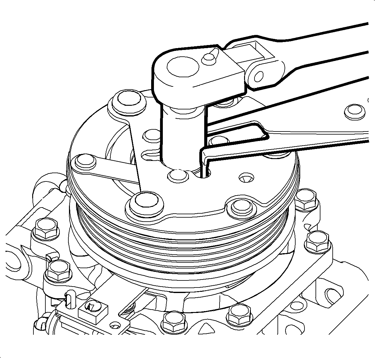
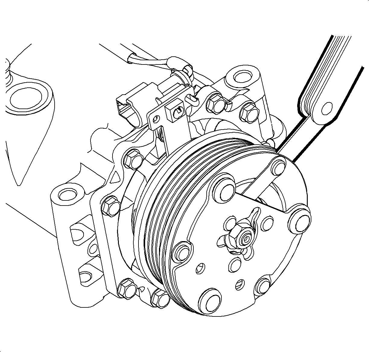
- Use J 45267 to hold the disk and hub assembly. Remove the clutch nut and the disk and hub assembly.
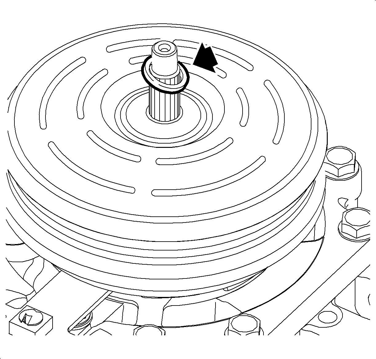
- Remove the spacer.
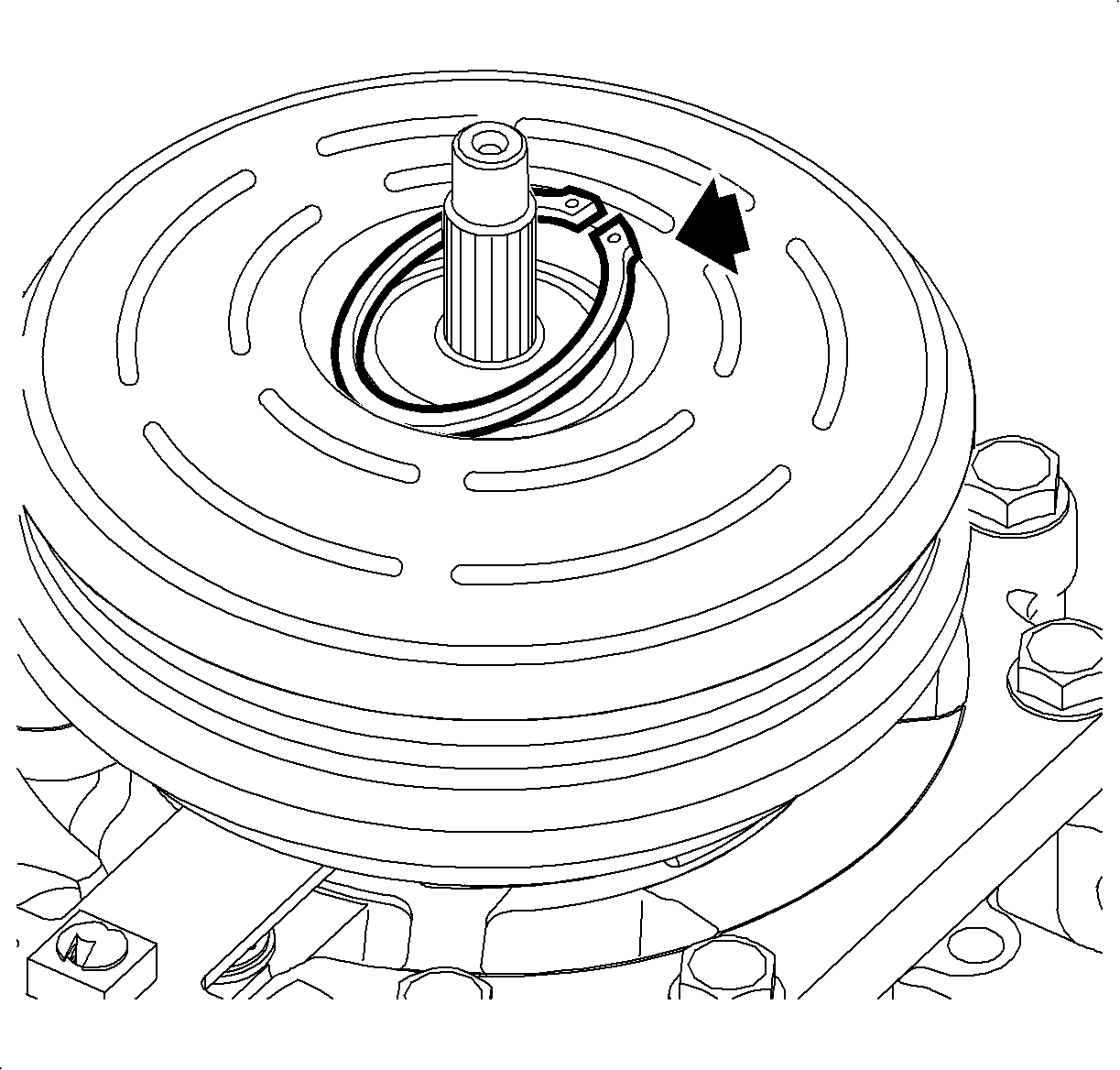
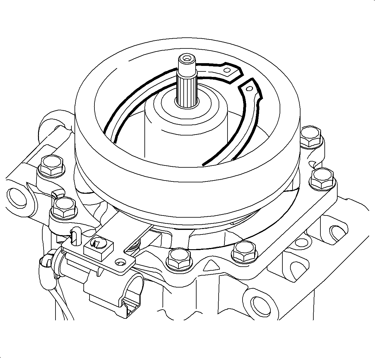
- Use SA9149AC-8 to remove the pulley snap ring.
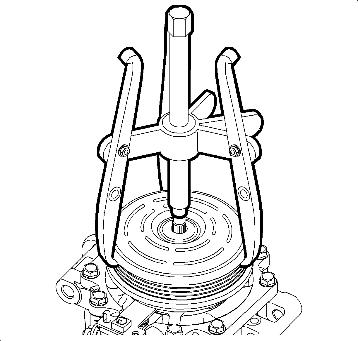
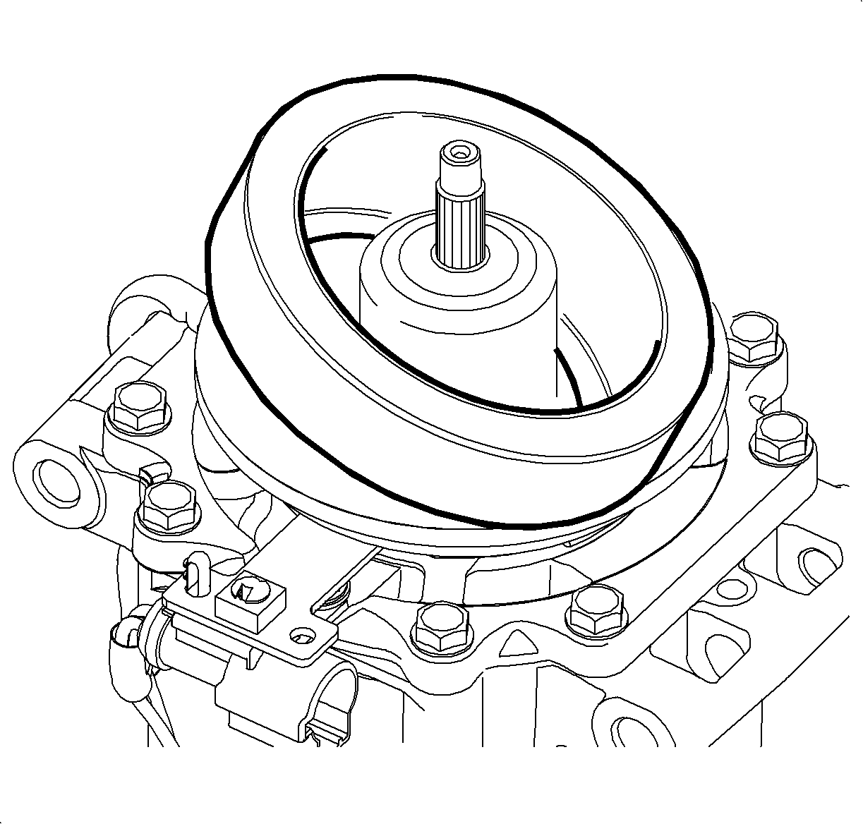
- Use J 25031-A to remove the A/C clutch pulley.
- Remove the thermal switch bolt and the hold-down bracket.
- Lift out the thermal switch while lightly twisting and pulling up on the sensor.
- Use SA9149AC-8 to remove the field coil snap ring.
- Remove the A/C clutch field coil.
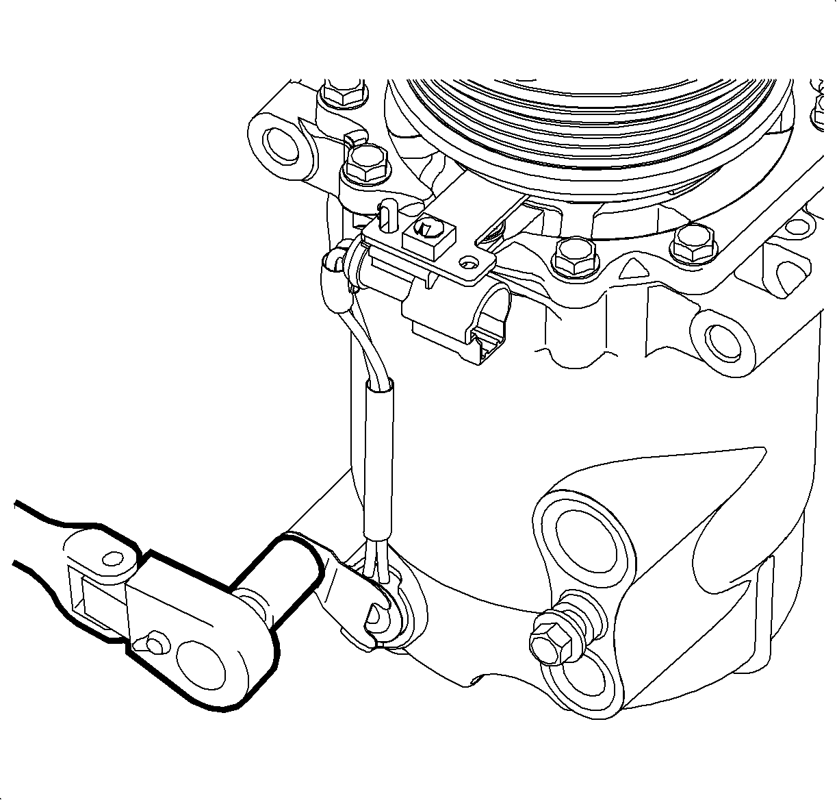
Important: It may be necessary to pry the switch lightly with a small screwdriver.
Installation Procedure
- Clean the mounting surfaces on the A/C clutch field coil and pulley.
- Install the A/C clutch field coil.
- Use SA9149AC-8 to install the field coil snap ring with the bevel side out.
- Clean the thermal switch pocket if necessary.
- Apply thermal switch sealant, approximately the size of a pea, into the switch pocket.
- Install the thermal switch by pushing the switch into place and wetting out the sealant, while holding the switch in place. Wipe away any excess sealant.
- Install the thermal switch hold-down bracket and bolt.
- Use J 45504 to align the clutch bearing/pulley assembly over the hub. Gently tap on the assembly to install.
- Use SA9149AC-8 to install the pulley snap ring with the bevel side out.
- Install the spacer.
- Install the drive plate and nut. Use the old nut to evaluate the clearances.
- Using a feeler gauge, measure the clearance between the pulley and the drive plate.
- If necessary, adjust the clearance by adding or removing clutch hub spacers.
- Once the correct air gap is obtained, install a new clutch nut. Use J 45267 to hold the disk and hub assembly while tightening.
- Install the compressor. Refer to Air Conditioning Compressor Replacement .
- Evacuate and charge the A/C system. Refer to Refrigerant Recovery and Recharging .
- Test the affected A/C joints for leaks usingJ 39400-A .


Important: It is important to use Saturn Sealant P/N 22681632 as a thermal conductive material. Failure to use this sealant may affect the function of the switch.
Notice: Use the correct fastener in the correct location. Replacement fasteners must be the correct part number for that application. Fasteners requiring replacement or fasteners requiring the use of thread locking compound or sealant are identified in the service procedure. Do not use paints, lubricants, or corrosion inhibitors on fasteners or fastener joint surfaces unless specified. These coatings affect fastener torque and joint clamping force and may damage the fastener. Use the correct tightening sequence and specifications when installing fasteners in order to avoid damage to parts and systems.
Tighten
Tighten the bolt to 6 N·m (53 lb in).
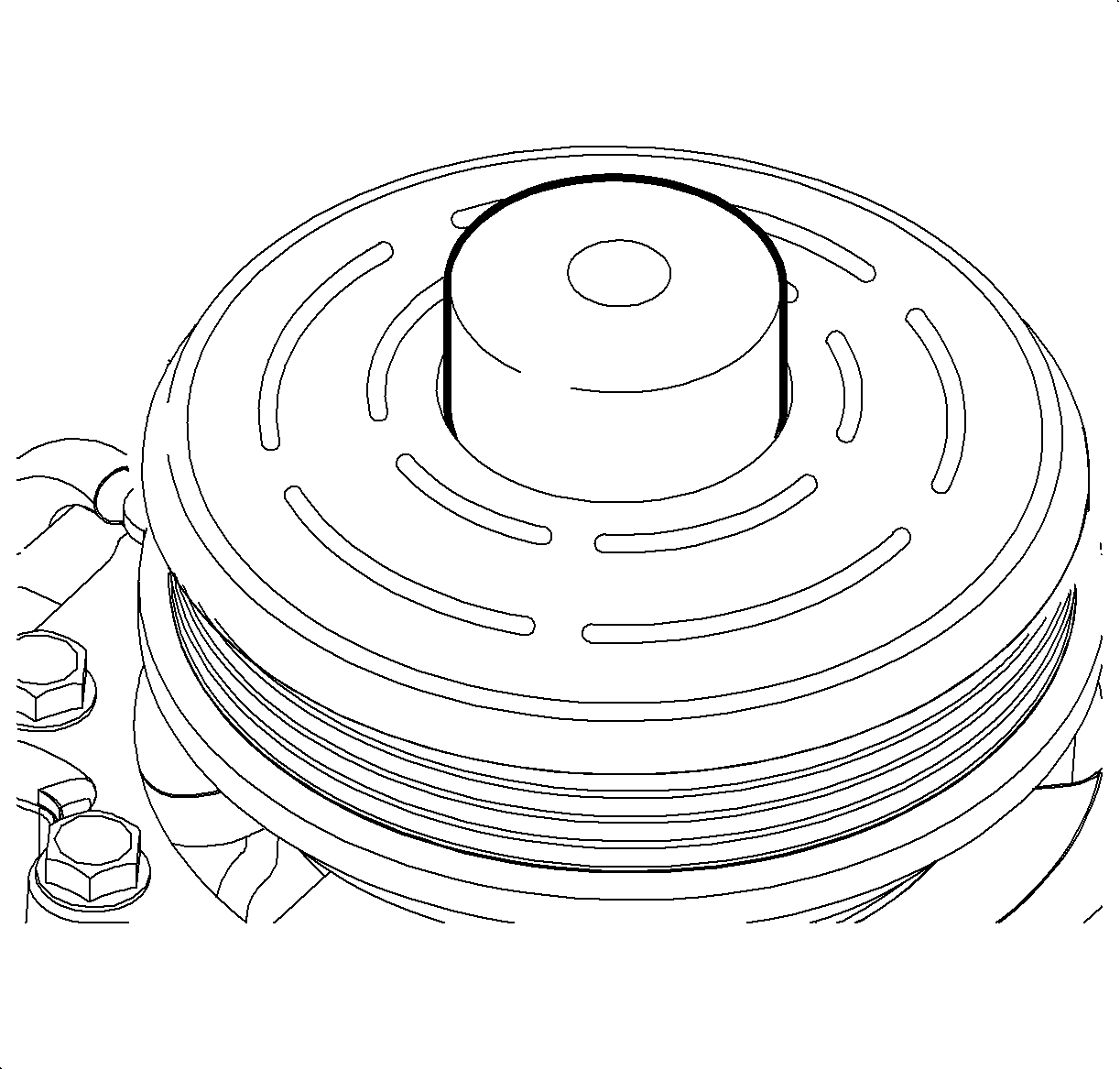
Important: The A/C clutch bearing and pulley is a slip fit on the compressor. If correctly aligned the pulley should slip on easily. If difficulty is encountered, install using the pulley installer tool.


Important: Align the block tooth on the disk and hub assembly with the groove in the shaft.
Measure
The clearance should be 0.35-0.75 mm (0.014-0.030 in).

Tighten
Tighten the nut to 19 N·m (14 lb ft).
