Tools Required
| • | J 44017 Shaft Remover |
| • | SA9133T Slide Hammer |
Removal Procedure
- Raise and support the vehicle. Refer to Lifting and Jacking the Vehicle in General Information.
- Remove the intermediate drive shaft. Refer to Intermediate Shaft Replacement in Wheel Drive Shafts.
- Disengage the PTU stub shaft from the PTU using the J 44017 and SA9133T .
- Remove the propshaft center bearing to underbody bolts.
- Remove the front propshaft attachment bolts.
- Compress the CV joint and disengage the propshaft from the PTU and secure with wire.
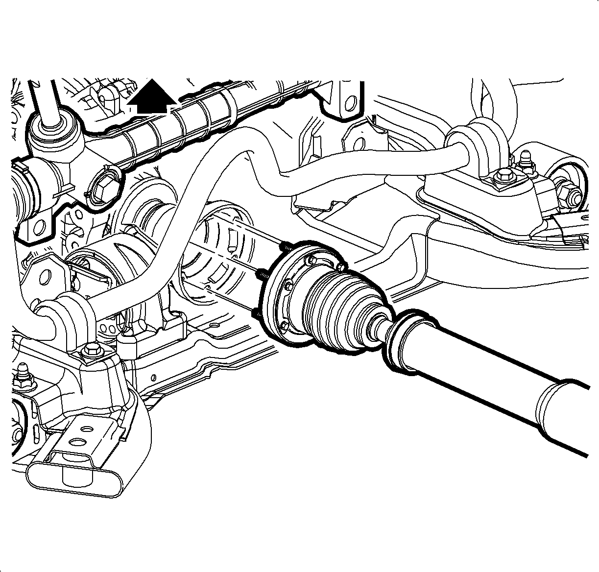
- Separate the steering gear from the cradle for clearance. Refer to Steering Gear Replacement .
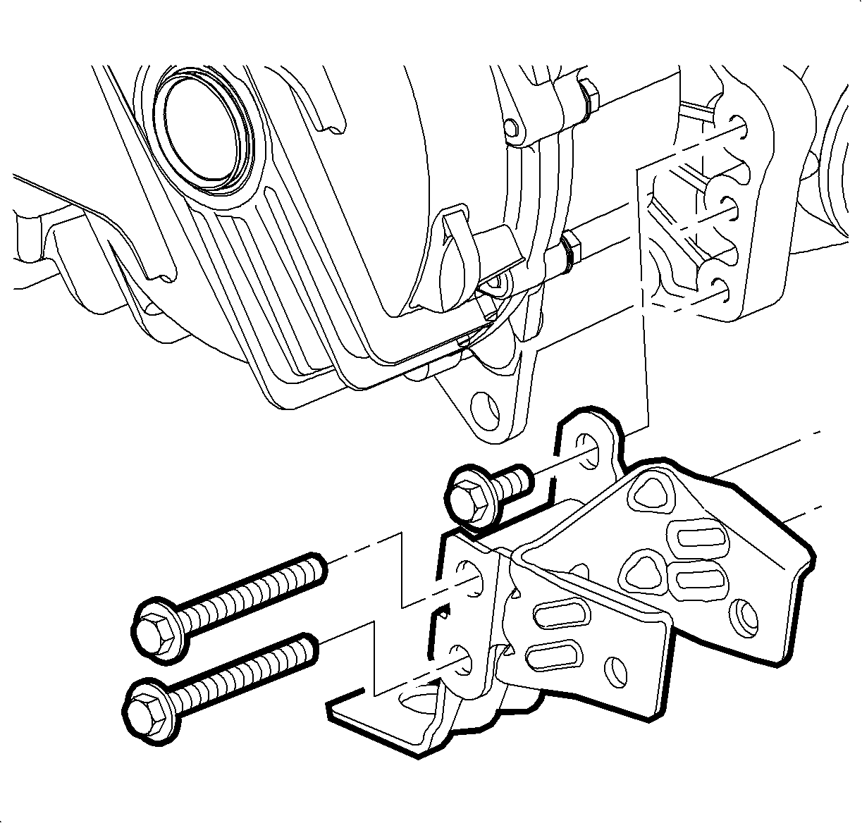
- Remove the rear powertrain mount bracket bolts from the PTU.
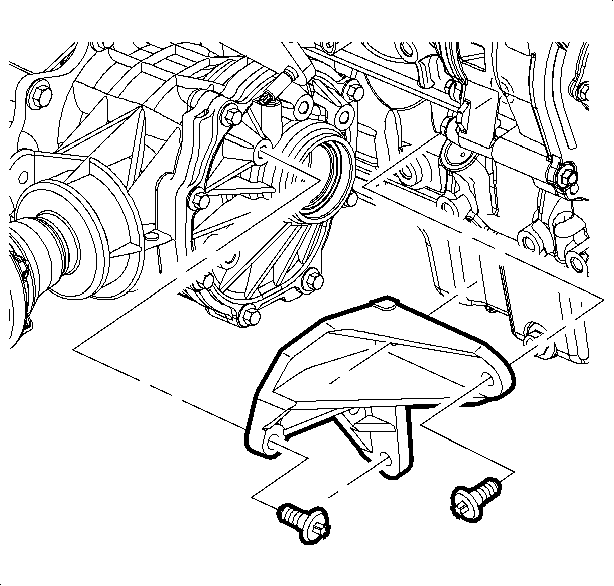
- Remove the PTU brace bolts and remove the brace.
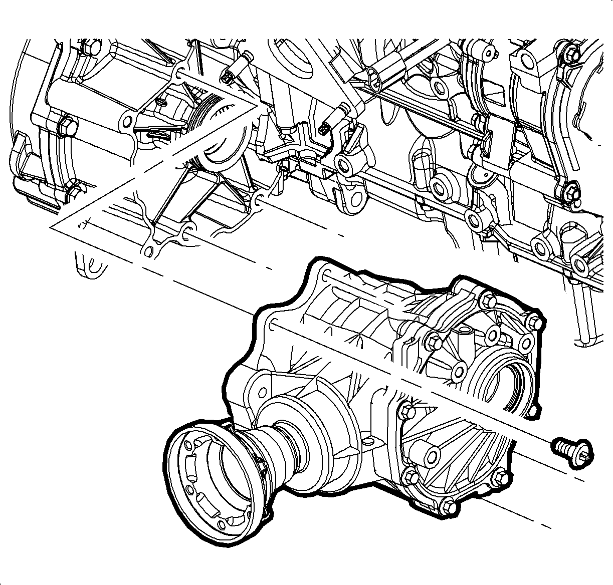
- Remove the PTU to transmission bolts.
- Remove the PTU vent hose.
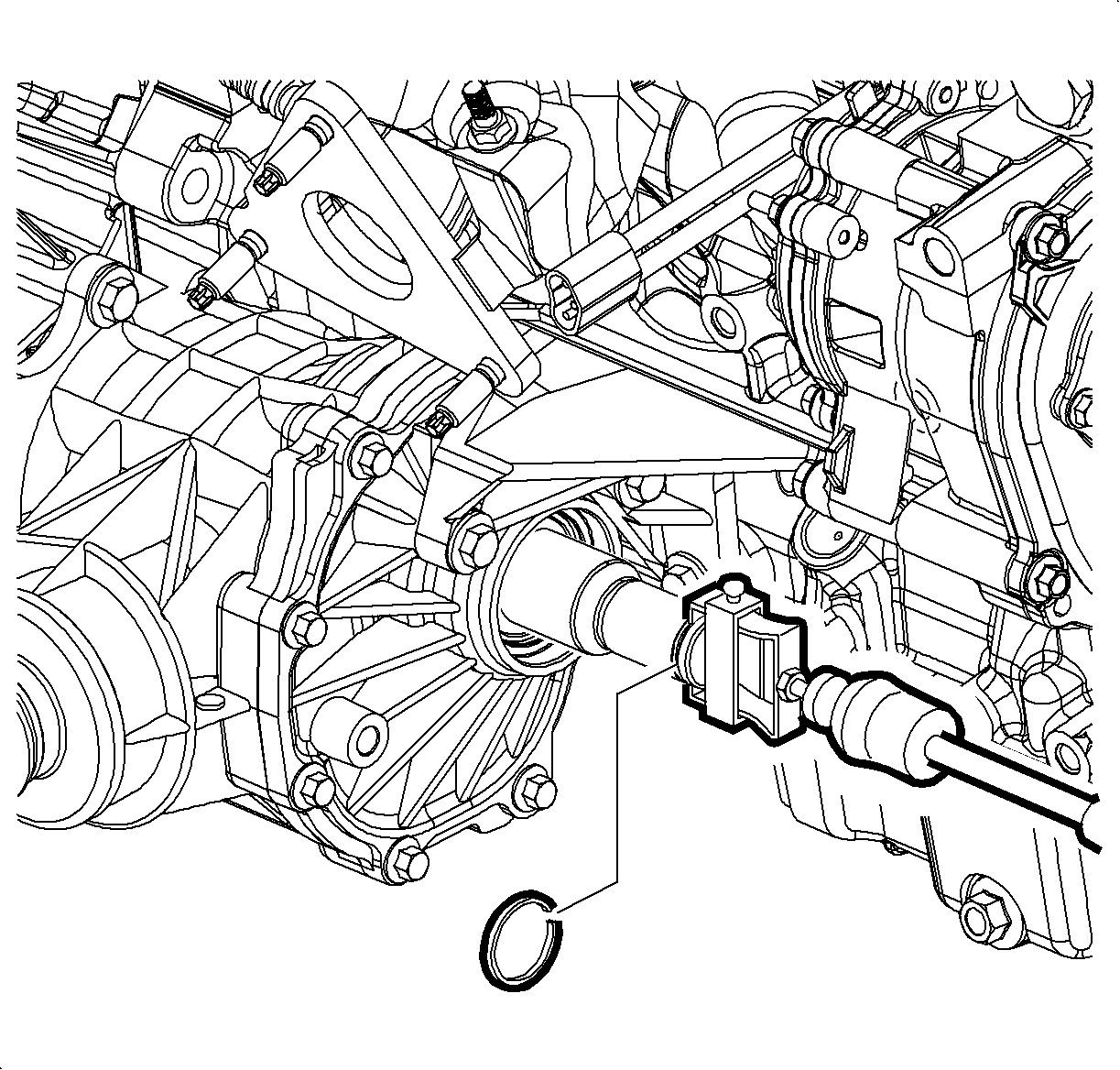
Important: Remove the retainer ring from the stub shaft for tool installation. Discard the used retainer ring.
Important: Use the proper container for fluid loss when the stub shaft is removed. Plug power take-off unit (PTU) to minimize fluid loss.
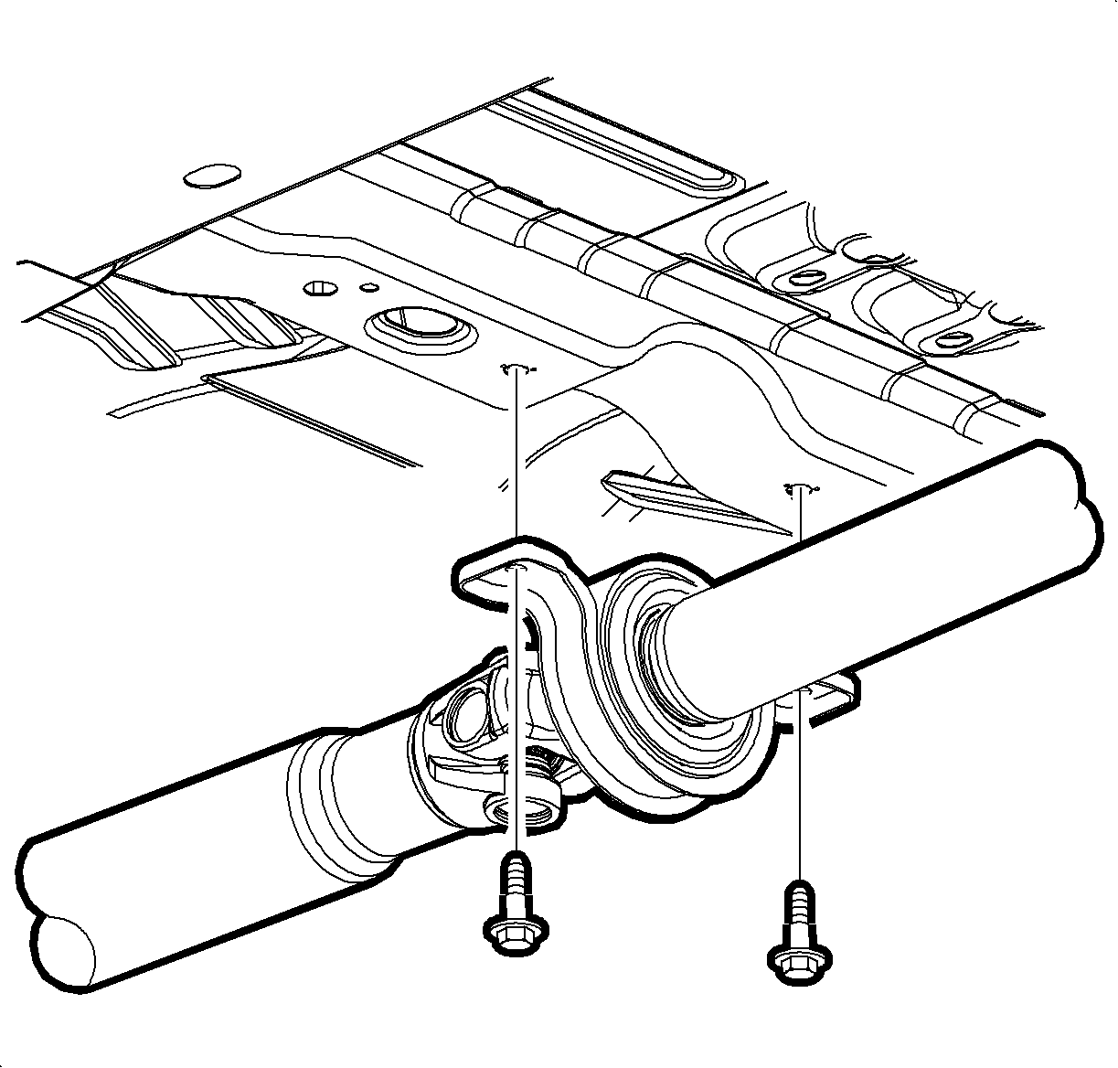
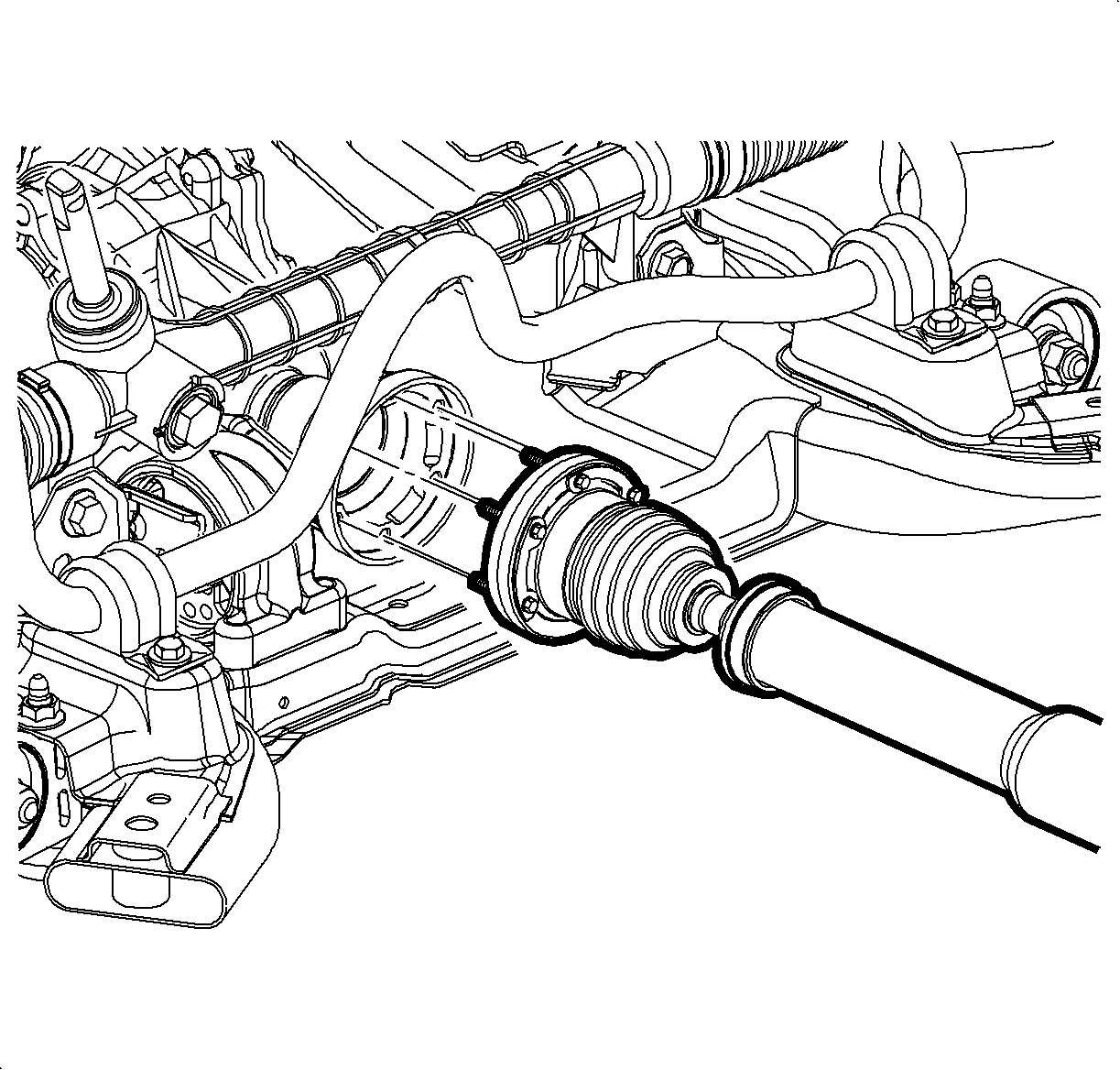
Important: Index mark the propshaft to PTU for re-installation.
Installation Procedure
- Inspect the transmission output shaft seal, replace if damaged.
- Install the PTU to transmission. Ensure the PTU is fully engaged. Hand start the PTU to transmission bolts. DO NOT tighten.
- Install the PTU brace. Hand start all 6 bolts.
- Tighten the PTU to transmission bolts.
- Tighten the PTU brace bolts.
- Hand start all the powertrain mount to PTU bolts and tighten.
- Hand start the propshaft center bearing bolts.
- Ensure all the PTU flange and propshaft coupling area is clean. Insert coupling into the PTU flange.
- Hand start all propshaft coupling bolts and tighten.
- Install the center bearing bolts.
- Install the intermediate drive shaft. Refer to Intermediate Shaft Replacement in Wheel Drive Shafts.
- Position the steering gear mounts to the cradle. Refer to Steering Gear Replacement .
- Install the PTU vent hose.
- Check the PTU fluid fill. Remove the fluid fill plug. Fill until fluid is just below the bottom of the fill hole.
- Lower the vehicle.
- Start the engine and observe idle shape. Compare to pre-removal condition. If excessive, perform powertrain balance procedure-operation #1. Refer to Powertrain Balance procedure.
- Check the transmission oil level and fill as required. Refer to Transmission Fluid Replacement in Automatic Transmission - VT25-E.

Important: Lubricate the seal with transmission fluid prior to PTU installation.

Notice: Refer to Fastener Notice in the Preface section.
Tighten
Tighten the bolts to 60 N·m (44 lb ft).
Tighten
Tighten the bolts to 60 N·m (44 lb ft).


Important: Use the index mark for reassembly.
Important: Apply Permatex Threadlocker®-Blue to bolt threads.
Tighten
Tighten the bolts to 25 N·m (19 lb ft).

Tighten
Tighten the bolts to 25 N·m (19 lb ft).
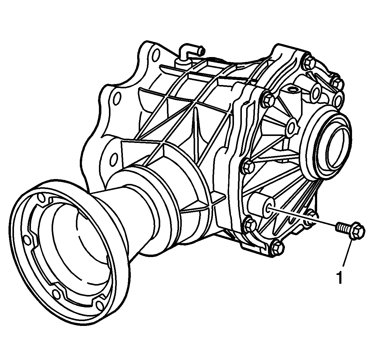
Important: Use sealant GM P/N 12345493 or equivalent on fill plug.
Specification
Add 500 ml (17 oz) PTU fluid.
Tighten
Tighten the fill plug to 15 N·m (11 lb ft).
