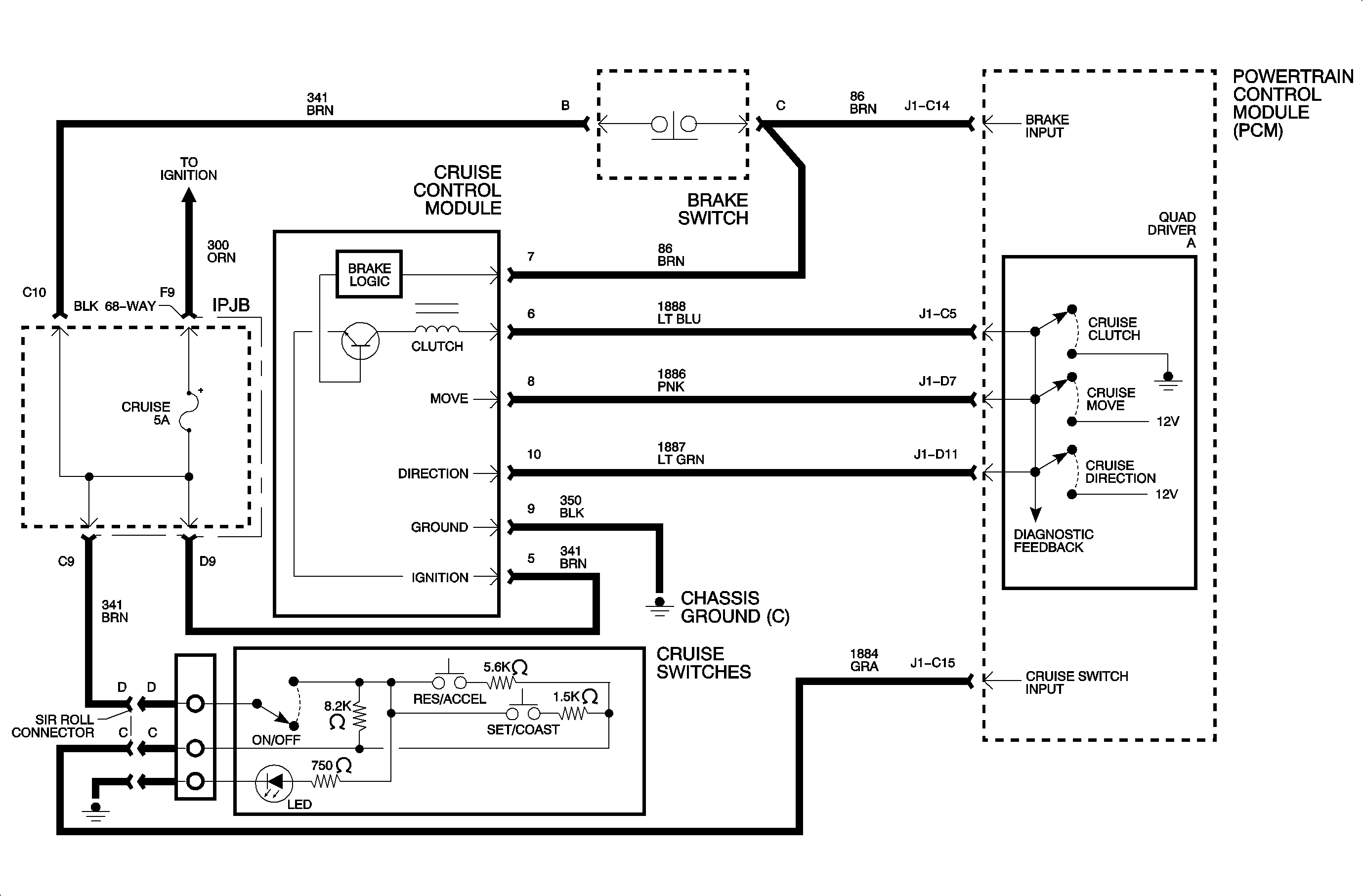
Circuit Description

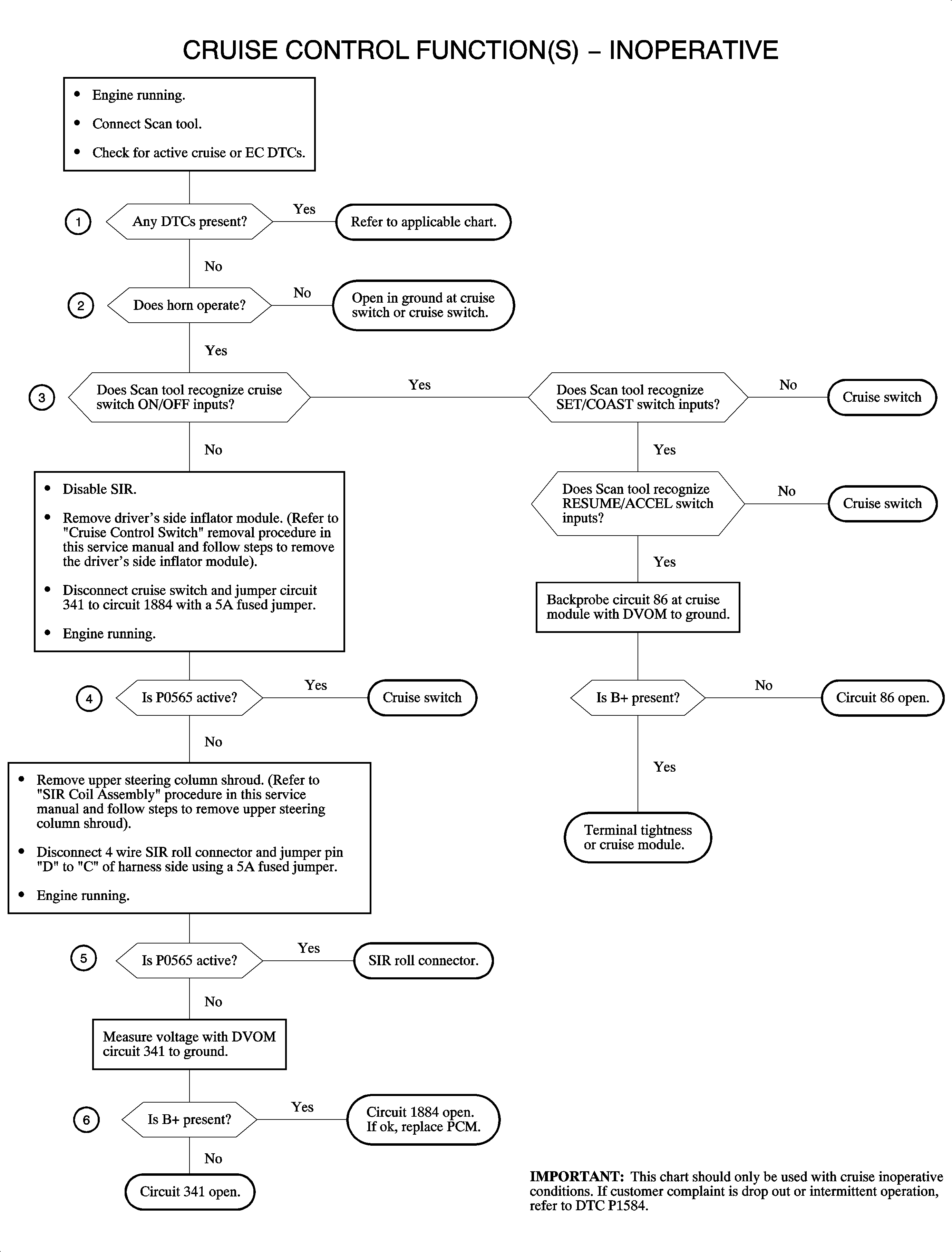
The cruise functions are not enabled until the powertrain control module (PCM)
recognizes the correct voltage from the cruise control ON/OFF switch. The following
flow chart verifies the integrity of the circuit and switch.
Test Description
- If any DTCs are present, diagnosis should begin with the specific DTC
chart.
- Verify the ground circuit at the cruise switch.
- If the PCM recognizes all switch inputs, circuit 1884 and the switch
are OK.
- Verify the cruise switch integrity.
- Verify the roll connector integrity.
- Verify the integrity of circuits 1884 and 341.
Diagnostic Aids
| • | If the complaint is an intermittent operation, refer to DTC P1584. |
| • | Special test functions will allow the scan tool to operate the cruise
rod from idle to 50 percent throttle angle. This will verify system operation. |
| • | If proper voltage level is not received from the ON/OFF switch on circuit 1884,
the system is never enabled. |
| • | On auto transaxle equipped vehicles, the PCM requires a brake switch transition
to occur to allow cruise enable. A rolling restart with no brake transition could
result in a cruise inoperative. |


