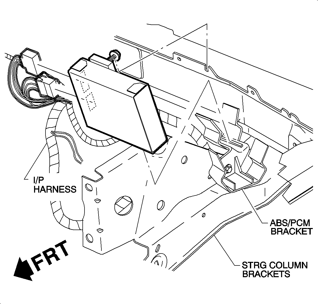
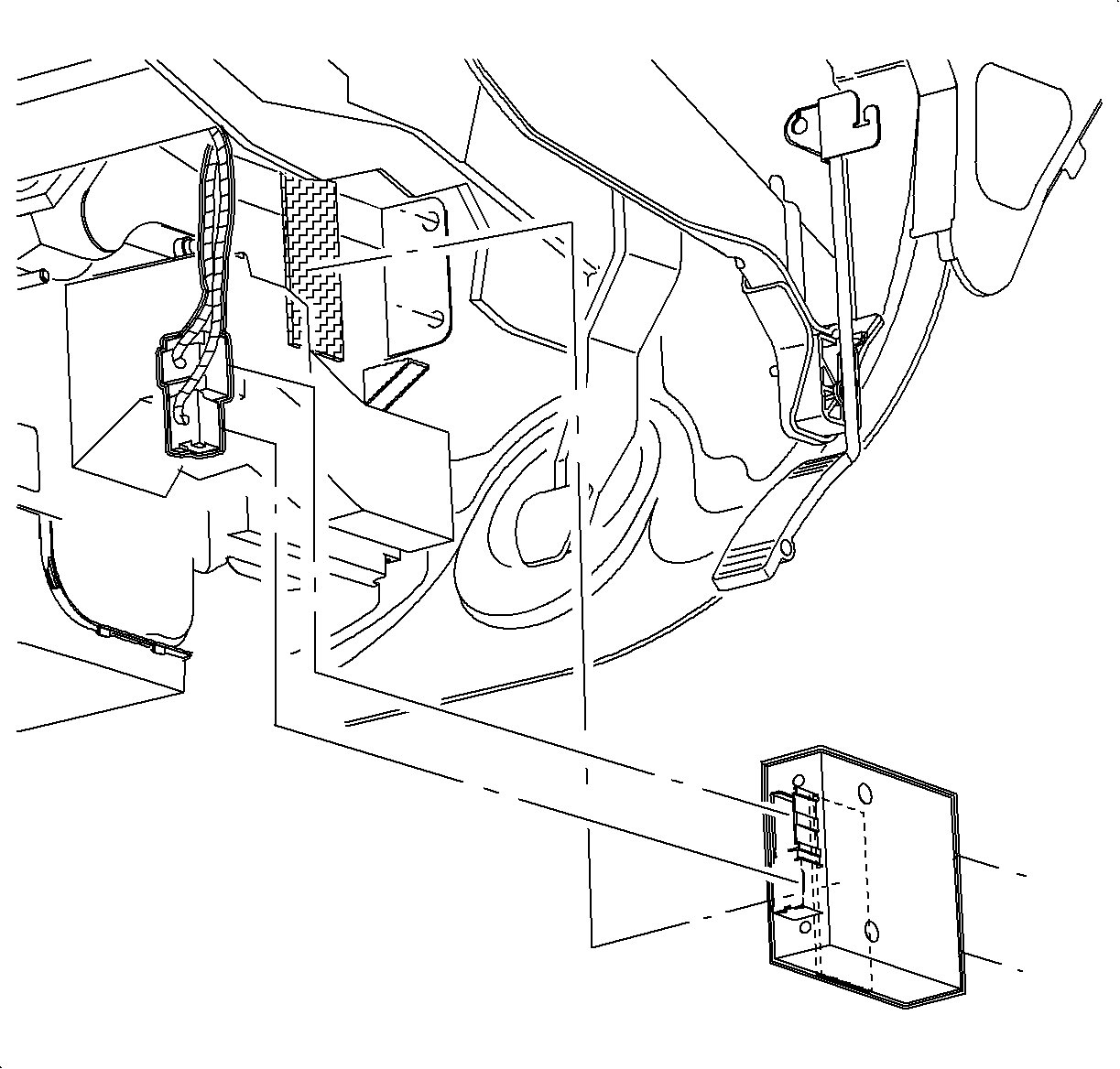
Electronic Brake Control Module Replacement LHD
Removal Procedure
- Remove I/P bolt caps by carefully prying with a small flat head screwdriver.
- Remove I/P upper trim panel screws.
- Lift I/P upper trim panel at clip locations on rear edge to disengage clips.
- Pull I/P upper trim panel rearward out of clips at bottom of windshield.
- Remove I/P upper trim panel.
- Remove I/P upper trim pad sound insulator.
- Loosen ABS module attachment nut at cross car beam and lift ABS module upward (towards windshield) to disengage ABS/PCM bracket.
- Disconnect ABS module electrical connectors and remove module.


Important: Be careful, when removing or replacing I/P upper trim panel rearward out of clips at bottom of windshield.
Important: Be careful, when removing upper trim panel, not to damage the upper trim panel seal (SL/SW only).


Installation Procedure
- Connect ABS module electrical connectors.
- Lower ABS module into bracket while guiding attachment stud into slot in cross car beam.
- Install nut and torque
- Install I/P upper trim pad sound insulator.
- Install I/P upper trim panel into clips at base of windshield.
- Lower I/P upper trim panel, making sure I/P upper trim panel alignment tabs interlock with windshield garnish slots (SL/SW only).
- Push down at clip locations to secure.
- Install I/P upper trim panel screws
- Install I/P bolt cap.
- Reprogram the electrically erasable programmable read only memory (EEPROM) using the Saturn Service Stall System (SSS).

Important: The ABS brake control module contains all calibrations. Reprogramming the ABS controller is not necessary.

Tighten
Tighten to 10 N·m (89 lb in).
Important: Make sure to tuck in all flaps.
Important: Be sure I/P upper trim panel seal is correctly seated on forward edge before installing upper trim panel (SL/SW only).
Important: Be careful, when removing or replacing upper trim panel, not to damage VIN Plate.

Important: The ABS control module contains an EEPROM that must be reprogrammed when a service replacement module is installed or a DTC 82 will result. (The ABS service replacement module will have a DTC 82 in it from the factory and can only be cleared by reprogramming the ABS control module with the correct calibration.)
Electronic Brake Control Module Replacement RHDD
Removal Procedure
- Disconnect ABS control module electrical connector.
- Grasp ABS control module, pull rearward to disengage front mounting tabs and dual-lock retainer.

Installation Procedure
- Install ABS control module front mounting tabs into bracket on HVAC module.
- Press ABS control module front mounting tabs into bracket on HVAC module.
- Connect electrical connectors.

Important: The ABS brake control module contains all calibrations. Reprogramming the ABS controller is not necessary.
