Cylinder and Camshaft Inspection SOHC
Tools Required
SA9179NE Dial Indicator
Inspection Procedure
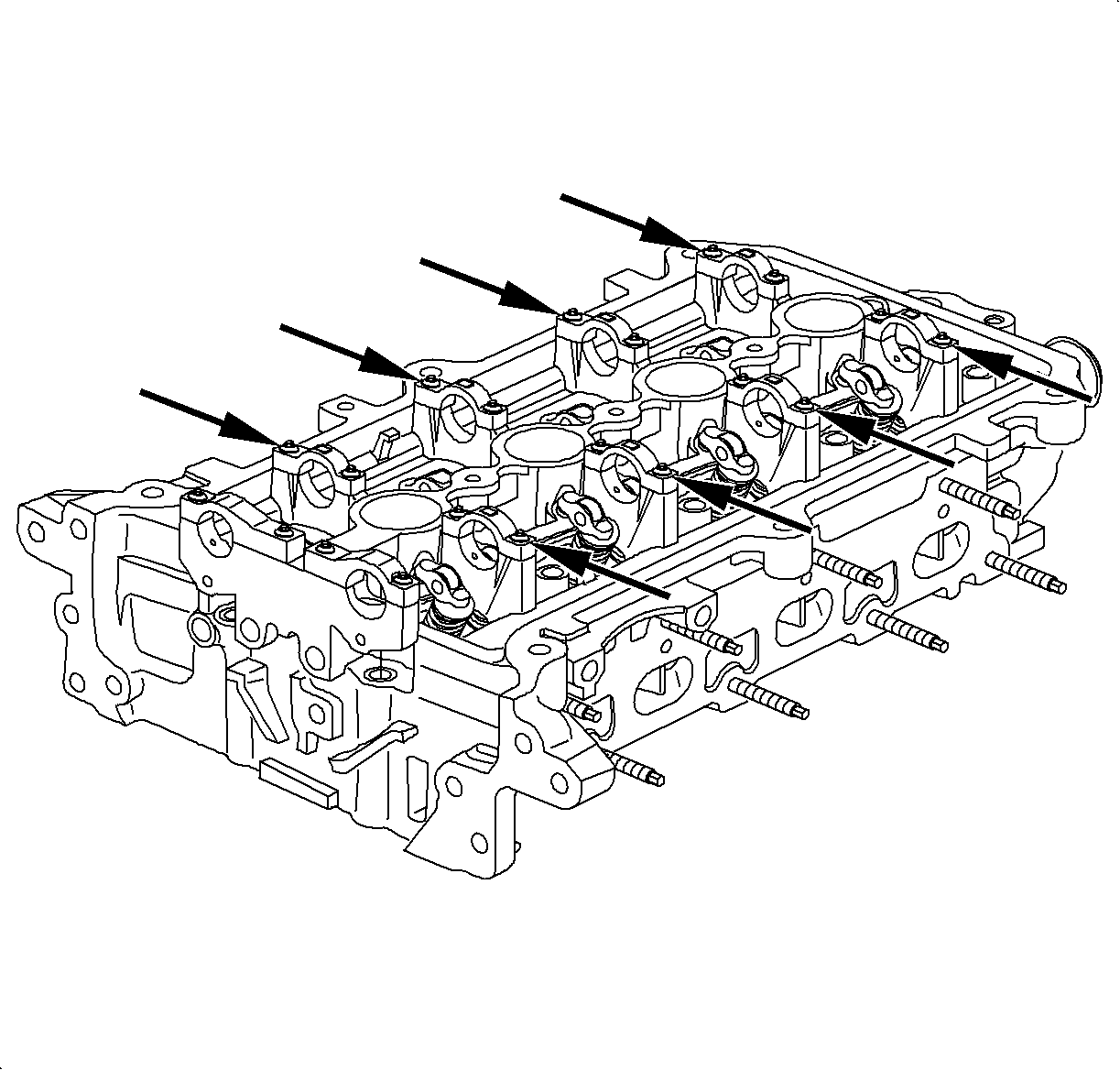
- Install camshaft and bearing caps. Refer to Cylinder Head Assembly procedure
for additional detail.
| 1.1. | Oil camshaft journals and install camshaft. Install the bearing caps with
arrows on caps pointed toward camshaft sprockets, front of cylinder head. |
| | Important: Bolt threads should be lightly oiled prior to installation. Holes must be clean
and free from oil and debris.
|
| 1.2. | Bolts must be pulled down uniformly. |
Tighten
Tighten camshaft bearing cap-to-head (LL0) to 14 N·m (10 lb in)
| 1.3. | Camshaft should rotate freely. If the camshaft binds, check for burrs
in the cylinder head and caps journals. |
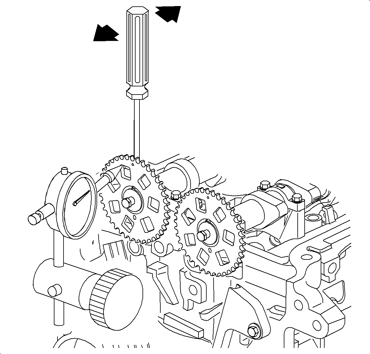
- Measure the camshaft thrust, end play. Using a SA9179NE
or equivalent, measure the thrust clearance while moving each camshaft
back and forth. If clearance is greater than maximum, replace the cylinder head or
camshaft.
Camshaft Thrust Clearance
| • | Standard: 0.006-0.396 mm (0.0002-0.0156 in) |
| • | Service Limit: 0.45 mm (0.018 in) max |
- Remove the camshafts from the cylinder head:
| 3.1. | Remove the bearing caps. |
| 3.2. | Remove each camshaft. |
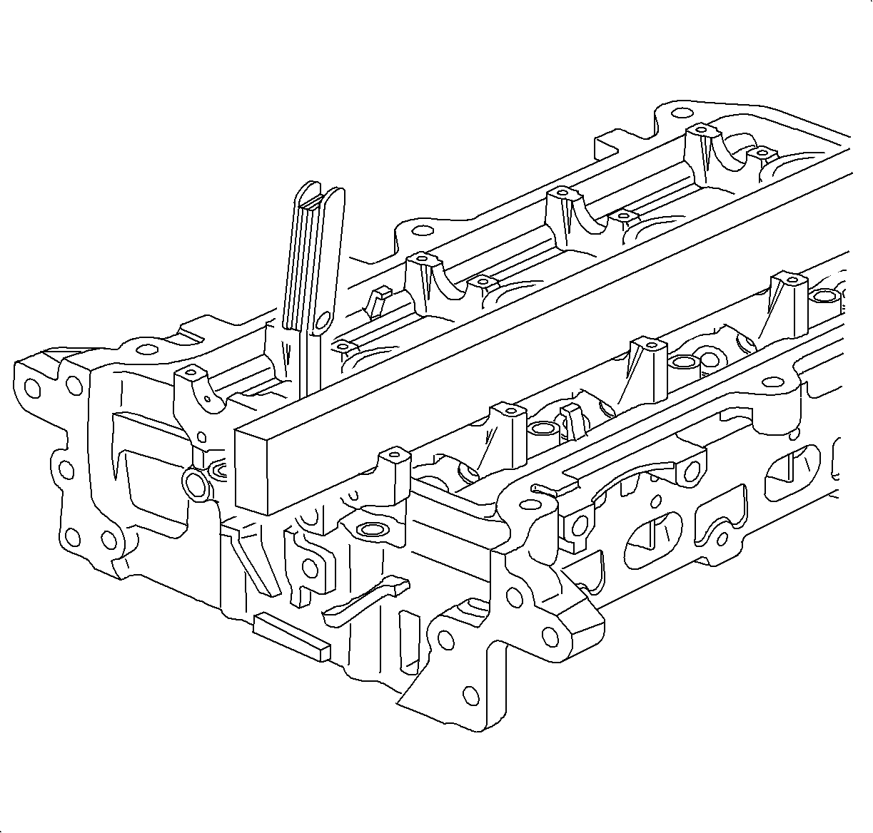
- Inspect camshaft bore for flatness. Using a precision straight edge and feeler
gauge, measure the surfaces contacting the camshaft for warpage. If warpage is greater
than maximum, replace the cylinder head.
Maximum Warpage
| • | Standard: 0.05 mm (0.0020 in) max |
| • | Service Limit: 0.075 mm (0.003 in) max |
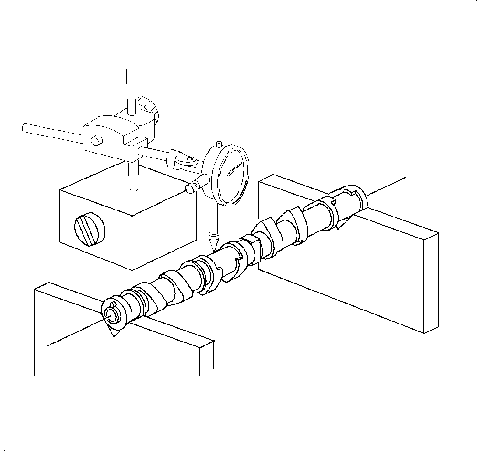
- Inspect camshaft:
- Place the camshaft ends in V-blocks and, using a dial indicator or service
tool SA9179NE
or equivalent, measure the
total runout at the center journal. If the runout is greater than maximum, replace
the camshaft.
Circle Total Runout
| • | Standard: 0.080 mm (0.003 in) max |
| • | Service Limit: 0.120 mm (0.0047 in) max |
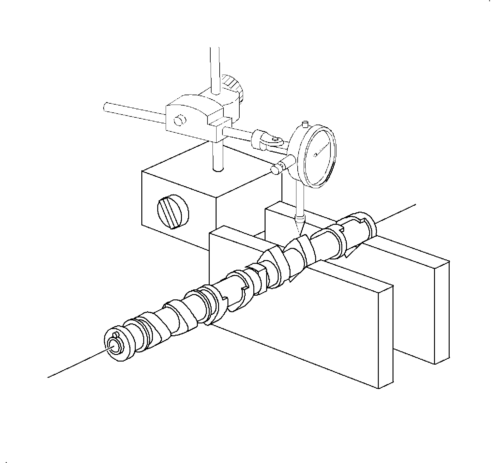
- Using a dial indicator, measure the cam lobe lift rise. Place the camshaft in
V-blocks located next to the lobe being measured.
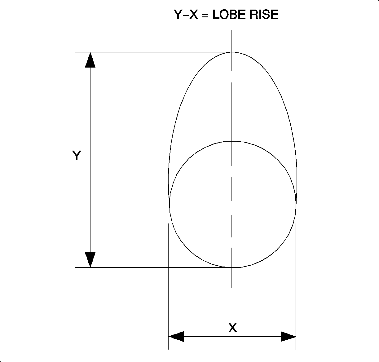
- If the cam lobe lift/rise is less than minimum, replace the camshaft.
Cam Lobe Lift Rise
| • | Standard: 5.183-5.263 mm (0.2042-0.2074 in) max |
| • | Service Limit: 5.133 mm (0.203 in) max |
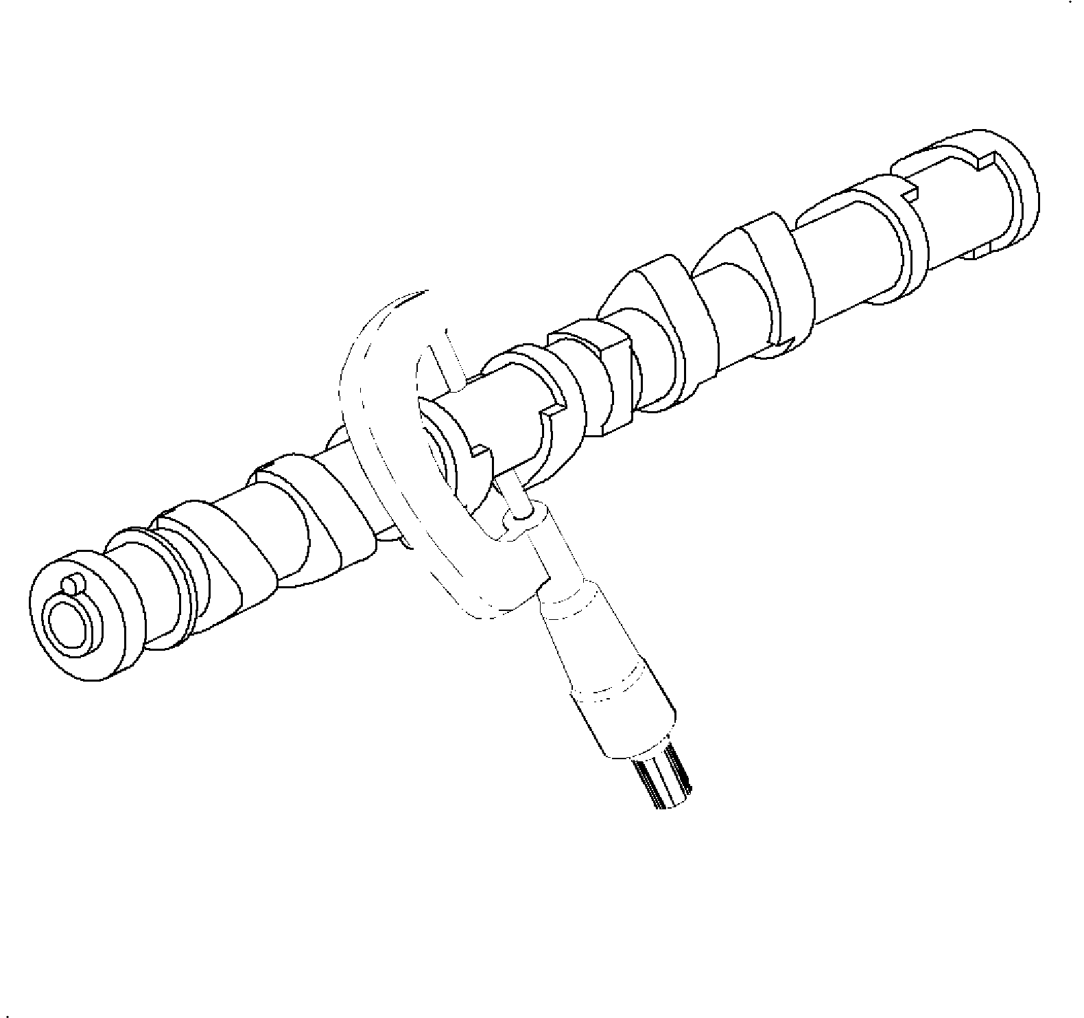
- Using a micrometer, measure the journal diameter.
Journal Diameter
| • | Standard: 26.950-26.970 mm (1.0638-1.0648 in) max |
| • | Service Limit: 26.925 mm (1.0608 in) max |
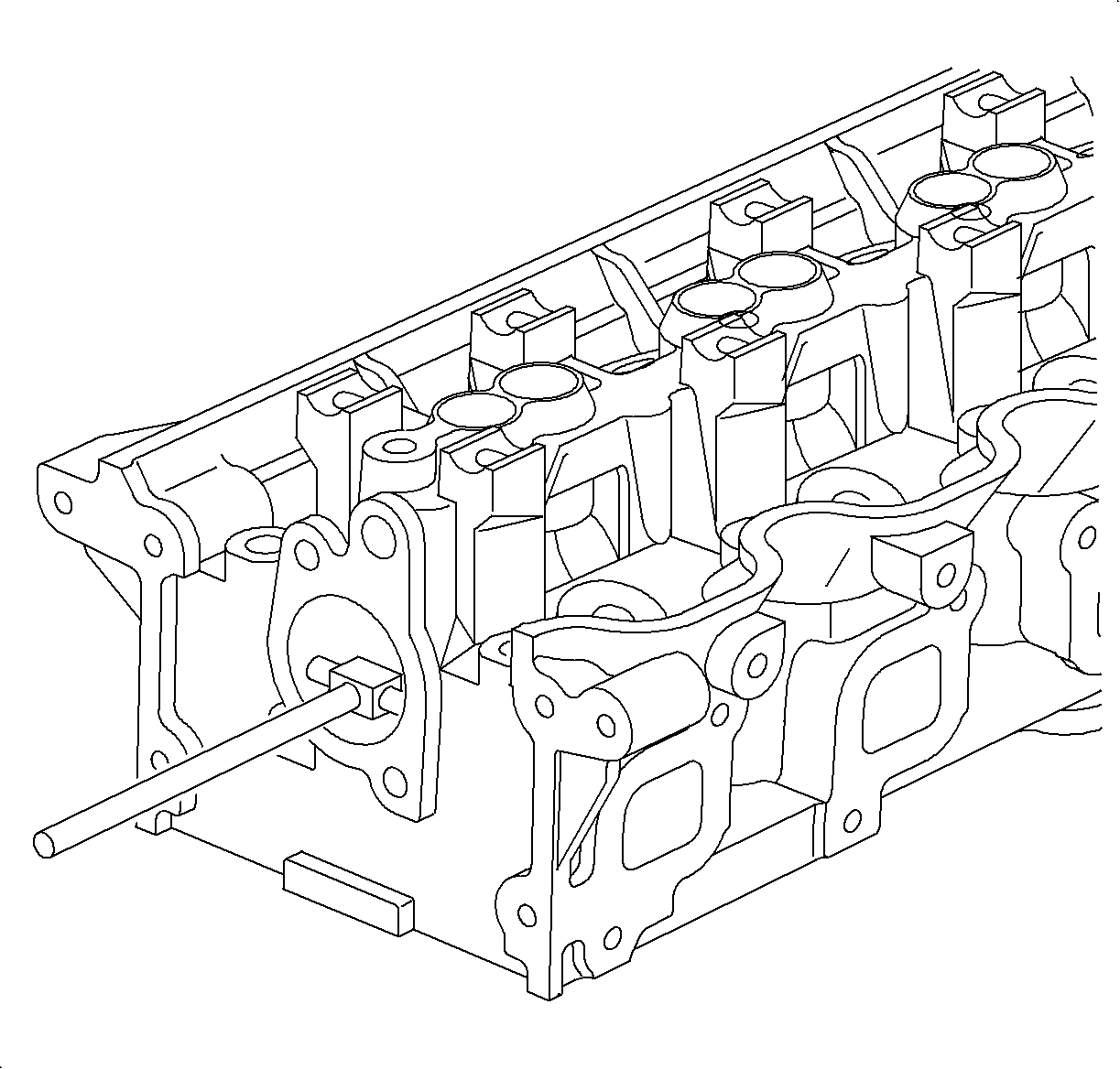
- Using an inside micrometer or SA91102NE
or equivalent, measure the housing bore diameter.
Bore Diameter
| • | Standard: 44.475-44.500 mm (1.751-1.752 in) max |
| • | Service Limit: 44.513 mm (1.753 in) max |
- Subtract the journal diameter measurement from the housing bore diameter
measurement. If the clearance is greater than maximum, replace the camshaft and/or
cylinder head.
Oil Clearance
| • | Standard: 0.51-1.101 mm (0.0020-0.0040 in) max |
| • | Service Limit: 0.138 mm (0.0054 in) max |
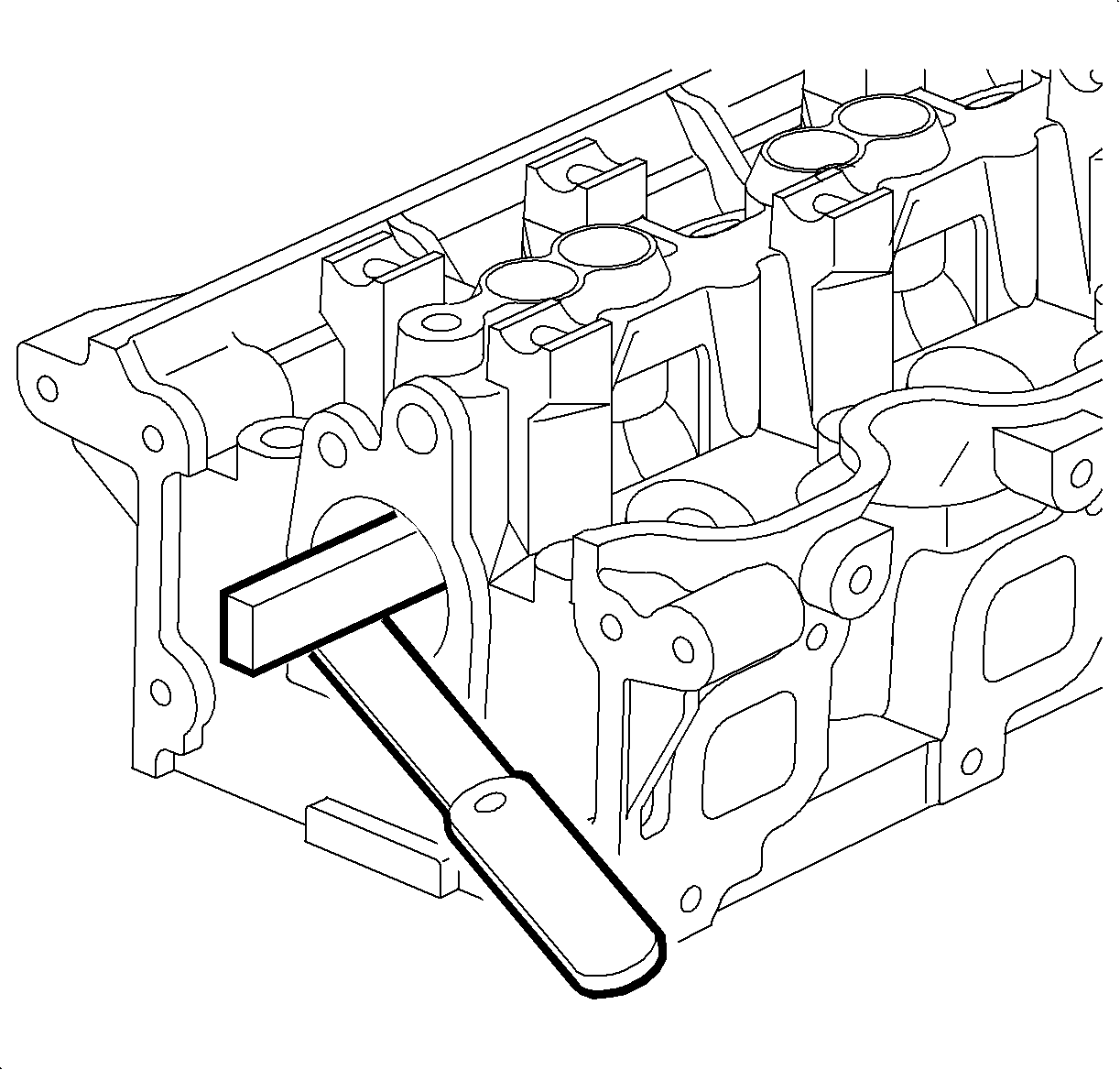
- Inspect camshaft bore for flatness. Using a precision SA9177NE
and SA91101NE
, measure the surfaces contacting the camshaft for warpage. If warpage
is greater than maximum, replace the cylinder head.
Maximum Warpage
| • | Standard: 0.05 mm (0.0020 in) max |
| • | Service Limit: 0.064 mm (0.0025 in) max |
Cylinder and Camshaft Inspection DOHC
Tools Required
SA9179NE Dial Indicator
Inspection Procedure

- Install camshaft and bearing caps. Refer to
Cylinder Head Assemble
for
additional detail.
| 1.1. | Oil camshaft journals and install the camshaft. Install the bearing caps
with the arrows on the caps pointed toward the camshaft sprockets, front of cylinder
head. |
| | Important: Bolt threads should be lightly oiled prior
to installation. Holes must be clean and free from oil and debris.
|
| 1.2. | Bolts must be pulled down uniformly. |
Tighten
Tighten camshaft bearing cap-to-head (LL0) to 14 N·m (10 lb in)
| 1.3. | The camshaft should rotate freely. If the camshaft binds, check for burrs
in the cylinder head and caps journals. |

- Measure the camshaft thrust (end play). Using a SA9179NE
or equivalent, measure the thrust clearance while moving each camshaft
back and forth. If clearance is greater than maximum, replace the cylinder head or
camshaft.
Camshaft Thrust Clearance
| • | Standard: 0.006-0.396 mm (0.0002-0.0156 in) |
| • | Service Limit: 0.45 mm (0.018 in) max |
- Remove the camshafts from the cylinder head:
| 3.1. | Remove the bearing caps. |
| 3.2. | Remove each camshaft. |

- Inspect camshaft bore for flatness. Using a precision straight edge and feeler
gauge, measure the surfaces contacting the camshaft for warpage. If warpage is greater
than maximum, replace the cylinder head.
Maximum Warpage
| • | Standard: 0.05 mm (0.0020 in) max |
| • | Service Limit: 0.075 mm (0.003 in) max |

- Inspect camshaft:
- Place the camshaft ends in V-blocks and, using a dial indicator or SA9179NE
, or equivalent, measure
the total runout at the center journal. If the runout is greater than maximum, replace
the camshaft.
Circle Total Runout
| • | Standard: 0.080 mm (0.003 in) max |
| • | Service Limit: 0.120 mm (0.0047 in) max |

- Using a dial indicator, measure the cam lobe lift rise. Place the camshaft in
V-blocks located next to the lobe being measured.

- If the cam lobe lift/rise is less than minimum, replace the camshaft.
Cam Lobe Lift Rise
| • | Standard: 5.183-5.263 mm (0.2042-0.2074 in) max |
| • | Service Limit: 5.133 mm (0.203 in) max |

- Using a micrometer, measure the journal diameter.
Journal Diameter
| • | Standard: 26.950-26.970 mm (1.0638-1.0648 in) max |
| • | Service Limit: 26.925 mm (1.0608 in) max |
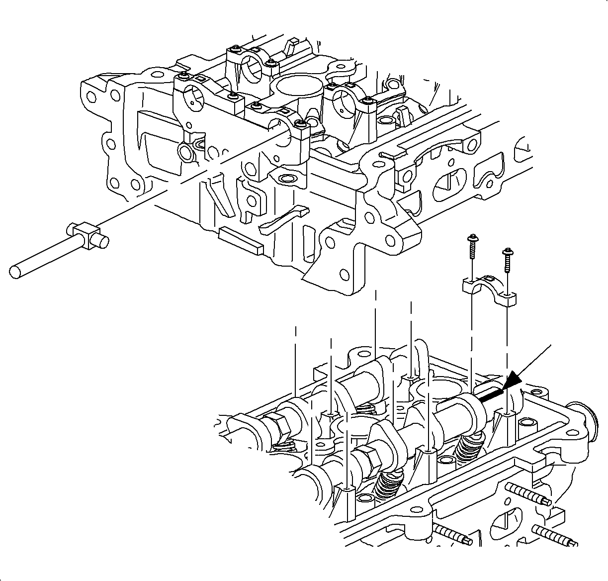
- Install the camshaft bearing caps. Using an inside micrometer, measure the housing
bore diameter.
Bore Diameter
| • | Standard: 27.000-27.026 mm (1.0638-1.0648 in) max |
| • | Service Limit: 27.05 mm (1.0658 in) max |
Important: Plastigage®, or equivalent can be used
to measure bearing clearance.
- Subtract the journal diameter measurement from the housing bore diameter measurement.
If the clearance is greater than maximum, replace the camshaft and/or cylinder head.
Oil Clearance
| • | Standard: 0.030-0.076 mm (0.0012-0.0030 in) max |
| • | Service Limit: 0.125 mm (0.005 in) max |


