2000 Saturn S- Series Vehicles (All Models)

| Subject: | INSPECTION AND REPLACEMENT OF BRAKE PIPES (IF NECESSARY) |
| Models: | 2000 SATURN S-SERIES VEHICLES (ALL MODELS) |
All Saturn Retailers and Authorized Service Providers
The Highway Safety Act, as amended, provides that each vehicle which is subject to a recall campaign of this type must be adequately repaired within a reasonable time after the customer has tendered it for repair. A failure to repair within sixty (60) days after tender of a vehicle is prima facie evidence of failure to repair within a reasonable time.
If the condition is not adequately repaired within a reasonable time, the customer may be entitled to an identical or reasonably equivalent vehicle at no charge or to a refund of the purchase price less a reasonable allowance for depreciation.
To avoid having to provide these burdensome remedies, every effort must be made to promptly schedule an appointment with each customer and to repair their vehicle as soon as possible. As you will see in reading the attached copy of the divisional letter that is being sent to customers, the customers are being instructed to contact the appropriate Customer Assistance Center if their dealer does not remedy the condition within five (5) days of the mutually agreed upon service date. If the condition is not remedied within a reasonable time, they are instructed on how to contact the National Highway Traffic Safety Administration.
Defect Involved
Saturn has decided that certain 2000 model year S-Series vehicles fail to conform to the requirements of Federal Motor Vehicle Safety Standard (FMVSS) #135, "Passenger Car Brake Systems." These vehicles were produced with brake pipe attachment nuts that may not be tightened to specification. If the brake pipe nuts are not properly tightened, brake fluid leakage could occur. Continuing to operate the vehicle with brake fluid leaking may result in illumination of the red 'BRAKE' warning light on the instrument panel, and/or an increase in brake pedal travel. If this condition were to occur in a situation where stopping distances were minimal, a vehicle crash could occur.
Vehicles Involved
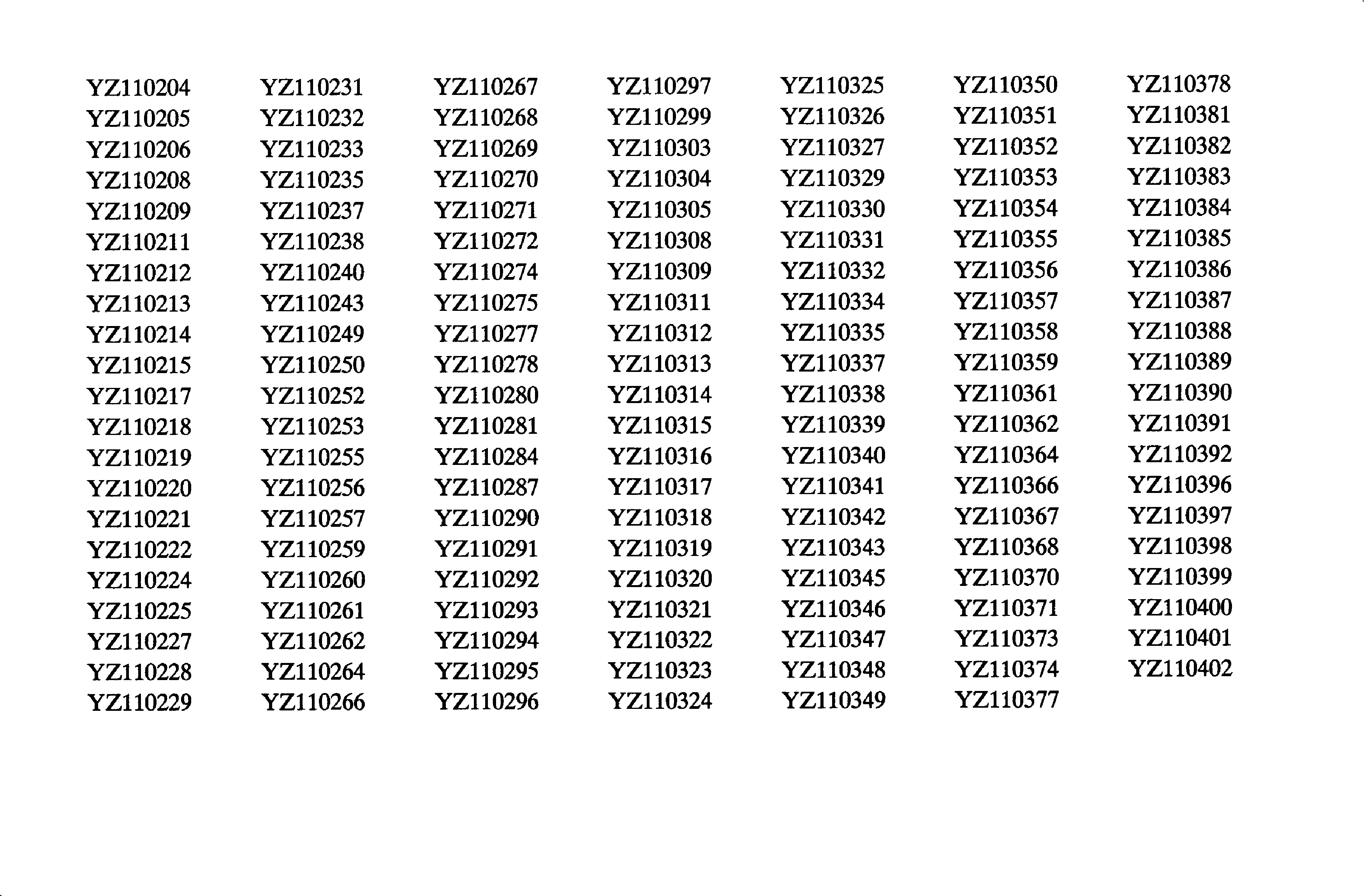
Only selected 2000 model year S-Series Saturn vehicles within the VIN range YZ100005 - YZ110402 will require this campaign. A VIN listing of the vehicles is included in this bulletin for your reference.
You must verify campaign involvement through your AS400 system, or with the listing attached to this bulletin. It is important to note that campaign claims will only be paid on involved vehicles.
Owner Notification
Owners of all involved vehicles will be notified of this campaign by Saturn. (Refer to the owner letter included in this bulletin.)
Facility VIN Listing
A list of vehicles assigned to you (Facility VIN Listing) , which our records indicate were sold by or shipped to you, (or are located in close proximity to your facility) is enclosed.
This listing contains:
| • | Owner's name with address and telephone number; |
| • | Complete vehicle identification number (VIN); and |
| • | VINs of vehicles which, according to Saturn records, are in route to your Retailer or already in retail stock. |
The Facility VIN Listing (with owner information) is furnished to involved Retailers with the Product Campaign Bulletin. Although these vehicles are assigned to your facility, it is important to note that owners may elect to have their vehicle serviced at the Saturn Retail Facility of their choice.
Those Retailers not involved initially in this campaign will receive a message at the top of a blank Facility VIN Listing that states: NO VEHICLES ASSIGNED AT THIS TIME FOR CAMPAIGN 00C05.
These listings may contain owner names and addresses obtained from State Motor Vehicle Registration Records. The use of such motor vehicle registration data for any other purpose is a violation of law in several states. Accordingly, you are urged to limit the use of this listing to the follow-up necessary to complete this campaign. Those records updated with California DMV registration information will have the following message printed adjacent to the appropriate VIN: "OWNER INFORMATION UPDATED BY CALIFORNIA DMV; PUBLICATION PROHIBITED."
Retailer Responsibility
All unsold vehicles in Retailers' possession and subject to this campaign must be held at the retail facility and repaired per the service procedure of this campaign bulletin before owners take possession of these vehicles.
Retailers are to service all vehicles subject to this campaign at no charge to owners, regardless of mileage, age of vehicle, or ownership, from this time forward.
Owners of vehicles recently sold from your vehicle inventory are to be contacted by the Retailer and arrangements made to make the required correction according to the procedure contained in this bulletin.
In summary, whenever a vehicle subject to this campaign enters your vehicle inventory, or is in your retail facility for service in the future, please take the steps necessary to be sure the campaign correction has been made before selling or releasing the vehicle.
Transfer of Campaign Responsibility
Saturn vehicles that have been sold by you, which may be closer in proximity to another Saturn Retailer, may still appear on your Facility VIN Listing. If either you or the vehicle owner determines that it is more desirable for a vehicle on your Facility VIN Listing to be serviced by another Saturn Retailer, or if the customer's address has recently changed, campaign responsibility may be transferred by completing the following:
| • | Submit a Campaign Vehicle Action Report to your Customer Assistance Manager (CAM) at the Saturn Customer Assistance Center; OR |
| • | Submit an update in owner information to the Saturn Owner of Record system, via SERVICELINE XL, for Saturn Customer Assistance Center review and approval. |
A copy of the Campaign Vehicle Action Report is included for your reference. Additional copies can be ordered from Saturn Publications (1-800-828-2112, prompt 3, Item #S0397050 ). All changes to campaign responsibility will be reflected in your next Unfixed VIN Report.
All other changes in vehicle status (e.g., scrapped, stolen, etc.) are to be made in accordance with section 4.4.3 of the Retailer Service Reference Guide, "Notifying Saturn of Vehicle Status Change."
Parts Information
- A shipment of brake pipe assemblies required to perform this campaign has been automatically sent to you from Saturn Service Parts Operations (SSPO). These shipments are to aid the Retailer in campaign preparation and ensure minimal customer inconvenience.
- Should additional parts be required, please contact your Parts Support Analyst (PSA) and we will expedite the shipment. Please do not enter any orders for any part numbers listed without first contacting your PSA.
- Required Parts:
Part Number | Description | Quantity Required Per Vehicle |
|---|---|---|
21012542 | Pipe Asm - RR Brk (Left) | 1 |
21012546 | Pipe Asm - Frt Brk (Left) | 1 |
21013048 | Pipe Asm - RR Brk (Right) | 1 |
21013345 | Pipe Asm - Frt Brk (Right) | 1 |
Disposition of Replaced Parts
Retailers will scrap all replaced parts in a manner that ensures that they cannot be reused, remanufactured, or otherwise entered into the stream of commerce in the future.
Suggestions for Ensuring Customer Satisfaction
As you know, Saturn's success hinges upon our ability to execute superior customer support throughout the ownership experience, especially when important corrective actions such as this are required.
It is imperative that every effort is made to accommodate the affected owners. Additionally, priority should be given to customer vehicles over retail inventory vehicles. If you have any questions, please coordinate with the Saturn Customer Assistance Center to help ensure customer satisfaction.
Torque and Inspect Brake Pipes
Materials Needed
| • | Torque Wrench 0-30 N·m (0-22 lb ft) |
| • | 12-mm Flare Nut Crows Foot |
| • | 14-mm Flare Nut Crows Foot |
| • | SA9150BR Brake Bleeder Adapter |
- Wipe all brake pipe to the master cylinder joints clean with a shop rag.
- Raise the vehicle on a hoist.
- Use a torque wrench to check the torque of the rear brake pipe to rear brake hose joint.
- Wipe both joints clean with a shop rag.
- Lower the vehicle.
- Exercise the brake hydraulic system by performing the following:
- Perform the following inspections:
- Based on the inspections performed above:
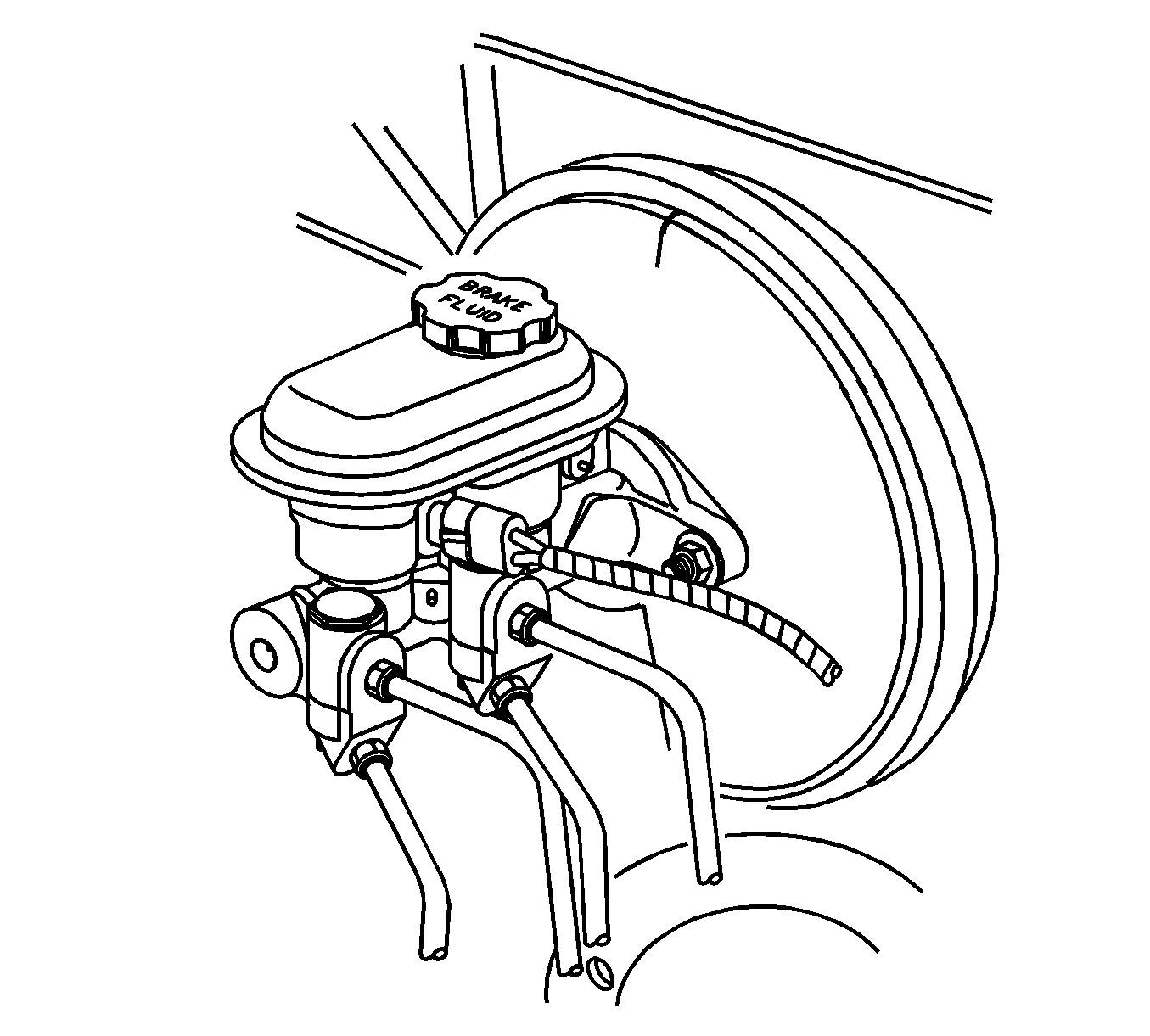
Caution: Make sure the vehicle is properly supported and squarely positioned on a hoist. To help avoid personal injury, provide additional support to the opposite end of the vehicle from which you will remove components.
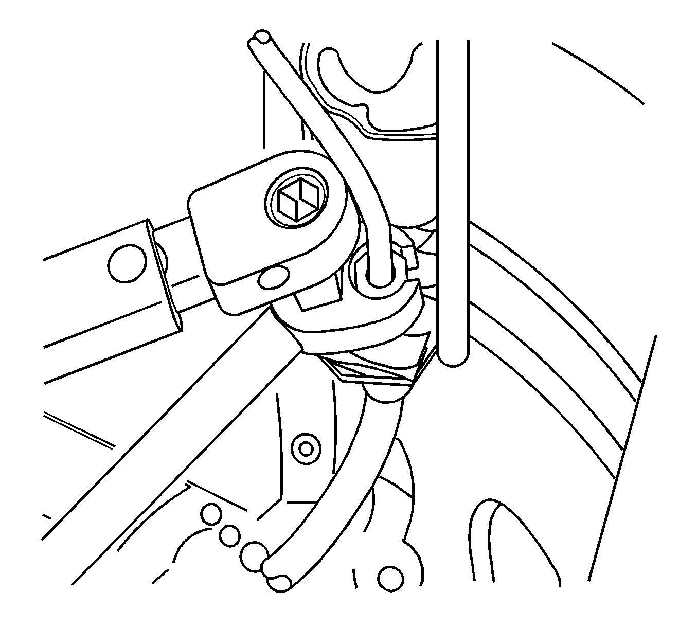
Notice: Always follow the recommended torque specifications and procedures. Over-torque or under-torque of a brake pipe connection may result in brake fluid leakage, brake pipe damage, or brake system failure.
Tighten
Tighten the joints to 18 N·m (14 lb ft).
| 6.1. | Start the vehicle. |
| 6.2. | Pump the brake pedal 10 times with moderate pressure. |
| 6.3. | Turn Off the vehicle. |
| 6.4. | Wait two minutes before continuing with this inspection. |
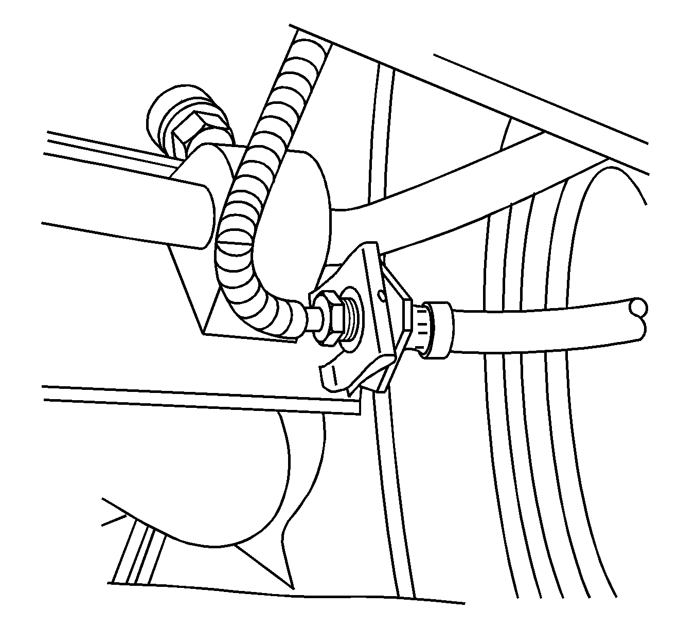
Caution: Make sure the vehicle is properly supported and squarely positioned on a hoist. To help avoid personal injury, provide additional support to the opposite end of the vehicle from which you will remove components.
| 7.1. | Raise the vehicle on a hoist. |
| 7.2. | Inspect the rear brake pipe to rear brake hose joints for visible signs of brake fluid leakage. |
| 7.3. | Lower the vehicle. |

| 7.4. | Inspect all 4 joints connecting the brake pipe to the master cylinder for visible signs of brake fluid leakage. |
| • | If brake fluid leakage is not present at any joints inspected, no additional repairs are necessary. |
| • | If brake fluid leakage is present at any of the joint(s) inspected, replace the affected brake pipe(s). Refer to the appropriate brake pipe replacement procedure in this bulletin. |
Brake Pipe Replacement - Left Front
- Remove the powertrain control module (PCM) attachment fasteners and move the PCM to gain access to the brake pipe to master cylinder joints.
- Place a shop rag under the master cylinder and disconnect the left front brake pipe.
- Remove the plastic 4-way brake pipe clamp located near the motor rail.
- Raise the vehicle on a hoist.
- Remove the splash shield from the left front wheelhouse area to gain access to the brake pipe.
- Disconnect the left front brake pipe from the left front brake hose.
- Remove the left front brake pipe from the vehicle.
- Obtain a replacement left front brake pipe, P/N 21012546.
- Install the left front brake pipe to the vehicle.
- Connect the brake pipe to the brake hose.
- Use a torque wrench to tighten the brake pipe to brake hose joint.
- Install the splash shield in the left front wheelhouse area.
- Lower the vehicle.
- Connect the left front brake pipe to the master cylinder.
- Position and install plastic 4-way brake pipe clamp.
- Install the PCM and the attachment fasteners.
- Bleed the brake system. Refer to "Manual Bleeding" or "Pressure Bleeding" in this bulletin.
- Test the brake system to ensure proper operation.
- Check for leaks.
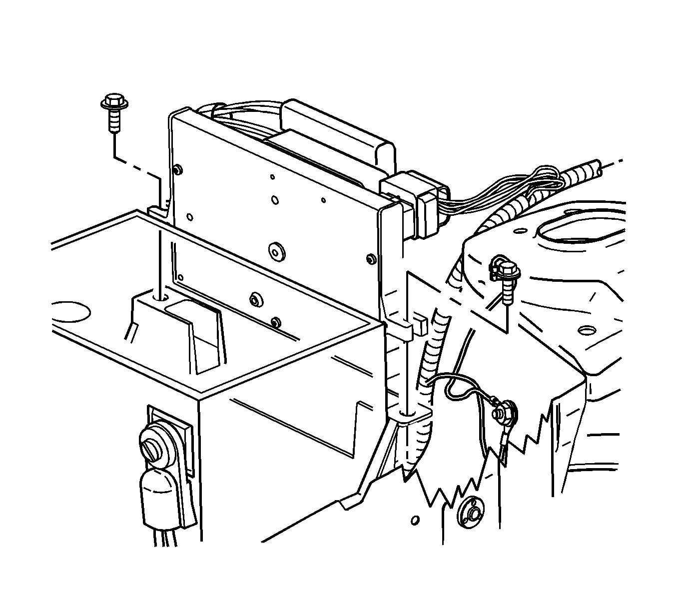
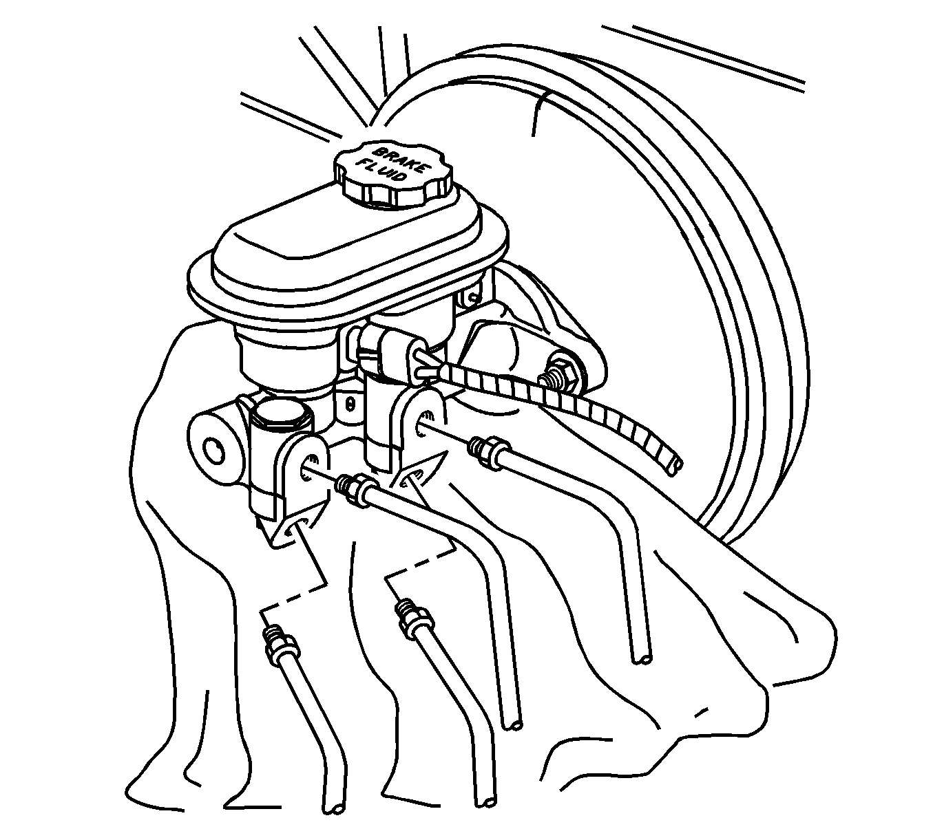
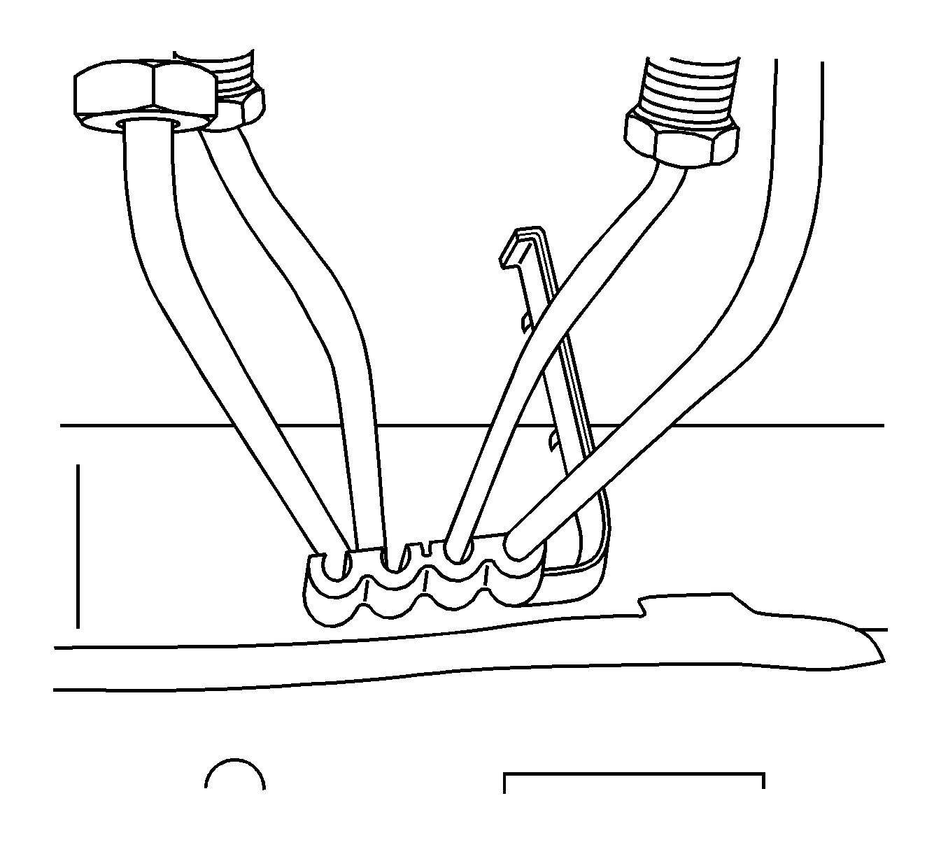
Caution: Make sure the vehicle is properly supported and squarely positioned on a hoist. To help avoid personal injury, provide additional support to the opposite end of the vehicle from which you will remove components.
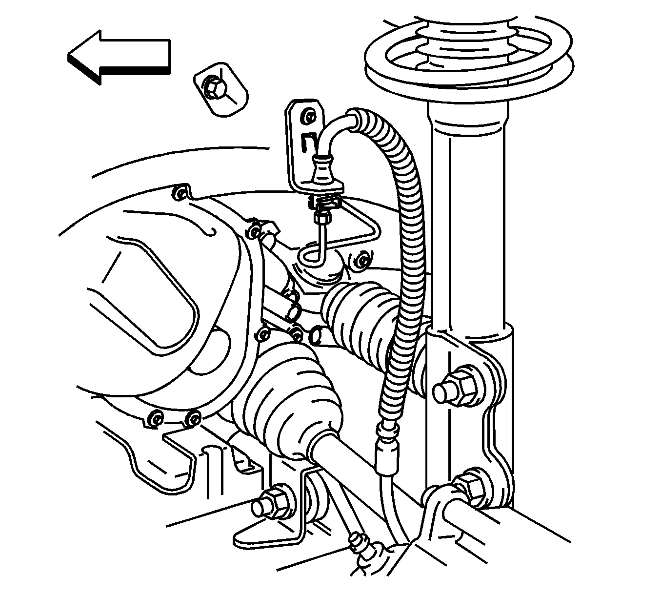
Notice: Always follow the recommended torque specifications and procedures. Over-torque or under-torque of a brake pipe connection may result in brake fluid leakage, brake pipe damage, or brake system failure.
Tighten
Tighten to 18 N·m (14 lb ft).
Tighten
Tighten to 27 N·m (20 lb ft).
Tighten
Tighten the fasteners to 6 N·m (53 lb in).
Brake Pipe Replacement - Right Front
- Remove the powertrain control module (PCM) attachment fasteners and move the PCM to gain access to the brake pipe to master cylinder joints.
- Place a shop rag under the master cylinder and disconnect the right front brake pipe.
- Remove the plastic 4-way brake pipe clamp located near the motor rail.
- Raise the vehicle on a hoist.
- Remove the splash shield from the right front wheelhouse area to gain access to the brake pipe.
- Disconnect the right front brake pipe from the right front brake hose.
- Remove the right front brake pipe from the pipe to cradle retaining clips.
- Remove the right front brake pipe from the vehicle.
- Obtain the replacement right front brake pipe, P/N 21013345.
- Install the right front brake pipe to the vehicle.
- Position and retain the right front brake pipe in the pipe to cradle retaining clips.
- Connect the brake pipe to the brake hose.
- Use a torque wrench to tighten the brake pipe to brake hose joint.
- Install the splash shield in the right front wheelhouse area.
- Lower the vehicle.
- Connect the right front brake pipe to the master cylinder.
- Position and install the plastic 4-way brake pipe clamp.
- Install the PCM and the attachment fasteners.
- Bleed the brake system. Refer to "Manual Bleeding" or "Pressure Bleeding" in this bulletin.
- Test the brake system to ensure proper operation.
- Test for leaks.


Caution: Make sure the vehicle is properly supported and squarely positioned on a hoist. To help avoid personal injury, provide additional support to the opposite end of the vehicle from which you will remove components.
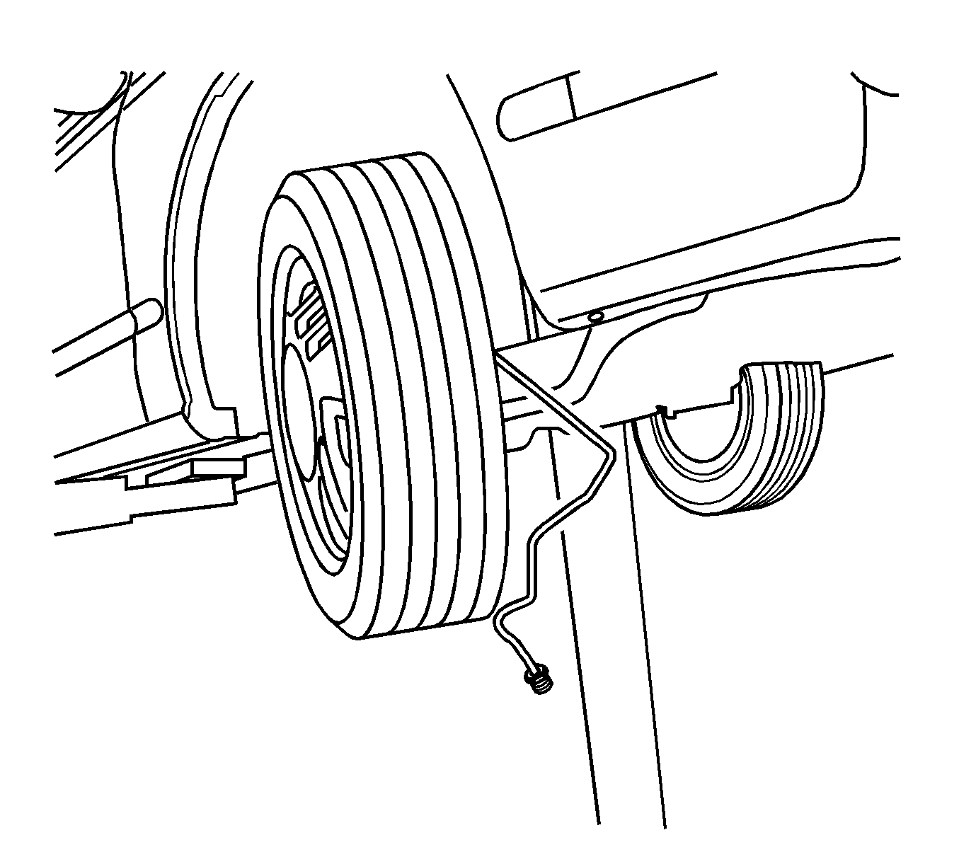
Notice: Always follow the recommended torque specifications and procedures. Over-torque or under-torque of a brake pipe connection may result in brake fluid leakage, brake pipe damage, or brake system failure.
Tighten
Tighten to 18 N·m (14 lb ft).
Tighten
Tighten the joint to 27 N·m (20 lb ft).
Tighten
Tighten the fasteners to 6 N·m (53 lb in).
Brake Pipe Replacement - Rear (Left, Right, or Both)
- Remove the powertrain control module (PCM) attachment and move the PCM to gain access to the brake pipe to master cylinder joints.
- Place a shop rag under the master cylinder and disconnect the affected rear brake pipe.
- Remove the plastic 4-way brake pipe clamp located near the motor rail.
- Raise the vehicle on a hoist.
- Remove the fuel line and the brake line shield.
- Remove the nuts that retain the rear brake pipe(s).
- Remove the plastic push-pin brake pipe retainer at the motor rail.
- Remove the trailing arm fastener that attaches the parking brake strap to the body.
- Disconnect the rear brake pipe(s) from the rear brake hose(s).
- If you are removing the right rear brake pipe, release the pipe from the retaining clips on the rear suspension.
- Remove the rear brake pipe(s) from the vehicle.
- Obtain a replacement brake pipe(s).
- Install the rear brake pipe(s) to the vehicle.
- If you are installing the right rear brake pipe, secure the pipe to the retaining clips on the rear suspension.
- Connect the brake pipe(s) to the brake hose(s).
- Use a torque wrench to tighten the joint between the brake pipe and the brake hose.
- Install the trailing arm fastener that attaches the parking brake strap to the body.
- Install the plastic push-pin retainer to brake pipes at the motor rail.
- Install the retaining clips on the brake pipes and the body attachment studs with nuts.
- Install the fuel line and the brake line shield to the body with bolts.
- Lower the vehicle.
- Connect the rear brake pipe(s) to the master cylinder.
- Position and install a plastic 4-way brake pipe clamp
- Install the PCM and the attachment fasteners.
- Bleed the brake system. Refer to "Manual Bleeding" or "Pressure Bleeding" in this bulletin.
- Test the brake system to ensure proper operation.
- Check for leaks.


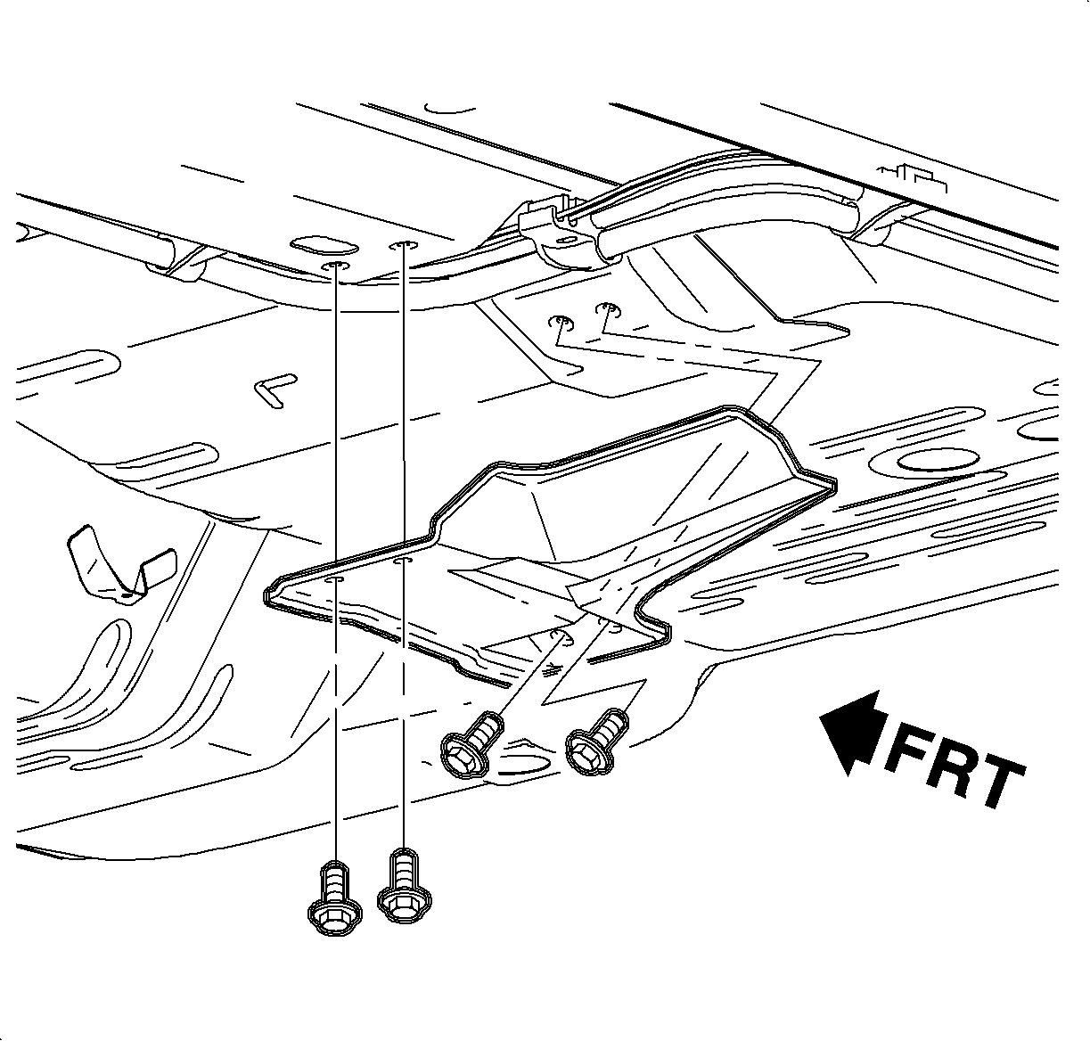
Caution: Make sure the vehicle is properly supported and squarely positioned on a hoist. To help avoid personal injury, provide additional support to the opposite end of the vehicle from which you will remove components.

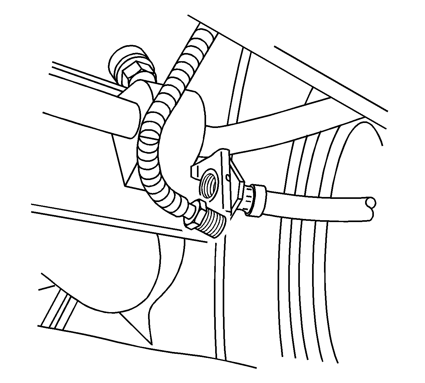
| • | Left Rear Brake Pipe, P/N 21012542 |
| • | Right Rear Brake Pipe, P/N 21013048 |
Notice: Always follow the recommended torque specifications and procedures. Over-torque or under-torque of a brake pipe connection may result in brake fluid leakage, brake pipe damage, and/or brake system failure.
Tighten
Tighten to 18 N·m (14 lb ft).

Tighten
Tighten to 140 N·m (103 lb ft).
Tighten
Tighten the nuts to 2.5 N·m (22 lb in).

Tighten
Tighten the bolts to 12 N·m (9 lb ft).
Tighten
Tighten to 27 N·m (20 lb ft).
Tighten
Tighten the fasteners to 6 N·m (53 lb in).
Manual Bleeding
- Fill the master cylinder reservoir with brake fluid. Keep the reservoir at least half full during the bleeding procedure.
- If the master cylinder is suspected of having air in its bore, it must be bled before proceeding to brake line bleeding.
- Bleed the individual calipers and the wheel cylinders in the following sequence:
- Check the brake pedal feel for sponginess. If the pedal exhibits this feel, repeat the bleeding procedure until the condition disappears.
- When the bleeding procedure is completed on each wheel, check the reservoir fluid level. Fill the as necessary.
Notice: Always follow the recommended torque specifications and procedures. Over-torque or under-torque of a brake pipe connection may result in brake fluid leakage, brake pipe damage, or brake system failure.
Notice: Brake fluid is corrosive to painted surfaces. Take care not to allow brake fluid to contact painted surfaces on vehicle.
Notice: Use only DOT 3 brake fluid from a clean, sealed container. Do NOT use any fluid from a container which is wet with water. Do NOT use DOT 5 silicone fluid.
| 2.1. | Loosen the left front brake pipe (front upper port) at the master cylinder. |

| 2.2. | Allow brake fluid to flow from the front master cylinder port. |
| 2.3. | Tighten the left front brake pipe into the master cylinder. |
Tighten
Tighten the pipe to 27 N·m (20 lb ft)
| 2.4. | Loosen the left front brake pipe at the master cylinder ¼ turn. |
| 2.5. | Depress the brake pedal slowly until fluid is seen coming from the pipe nut. |
| 2.6. | Once again, tighten the left front brake pipe into the master cylinder while pedal is being depressed. |
Tighten
Tighten the pipe to 27 N·m (20 lb ft)
| 2.7. | Slowly release the pedal. |
| 2.8. | Repeat the sequence until all air is removed from the front (secondary) master cylinder bore. |
| 2.9. | Loosen the right front brake pipe (rear upper port) at the master cylinder. |
| 2.10. | Allow brake fluid to flow from the rear master cylinder port. |
| 2.11. | Tighten the right front brake pipe into the master cylinder. |
Tighten
Tighten the pipe to 27 N·m (20 lb ft)
| 2.12. | Loosen the right front brake pipe at the master cylinder ¼ turn. |
| 2.13. | Depress the brake pedal slowly until fluid is seen coming from the pipe nut. |
| 2.14. | Once again, tighten right front brake pipe into master cylinder while pedal is being depressed. |
Tighten
Tighten the pipe to 27 N·m (20 lb ft)
| 2.15. | Slowly release the pedal. |
| 2.16. | Repeat this sequence until all air is removed from the rear (primary) master cylinder bore. |
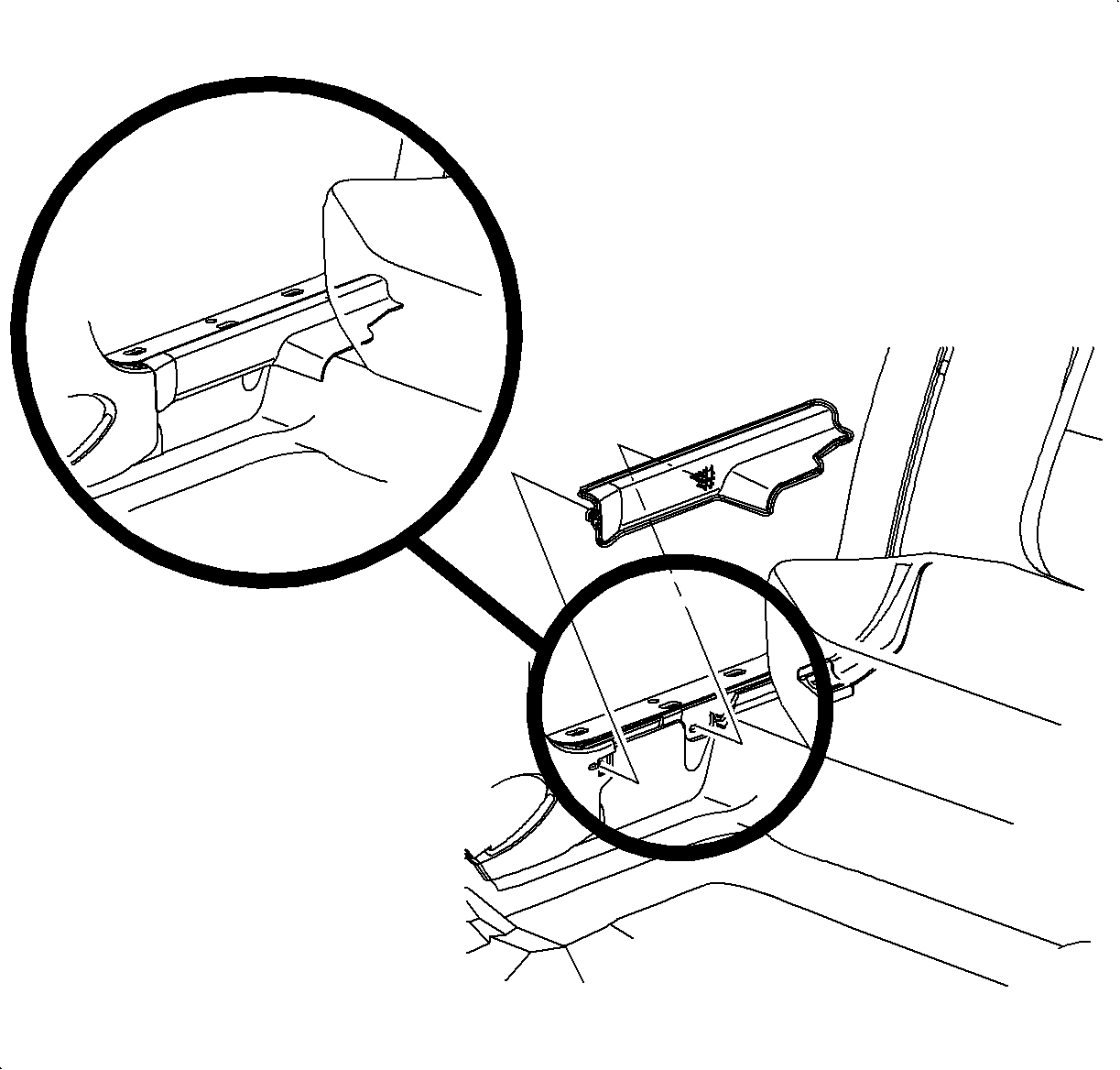
| • | Right rear (A) |
| • | Left front (B) |
| • | Left rear (C) |
| • | Right front (D) |
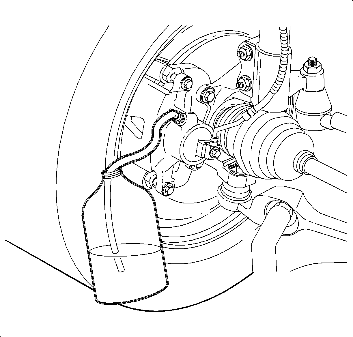
| Important: To assist in freeing entrapped air, tap lightly on caliper and wheel cylinder castings with a rubber mallet. |
| 3.1. | Place a wrench over the bleeder valve. |
| 3.2. | Attach a transparent hose over the bleeder valve nipple. Submerge the other end of the hose into a transparent container of brake fluid. |
| 3.3. | Loosen the bleeder screw. |
| 3.4. | Apply the brake pedal slowly and hold. |
| 3.5. | Tighten the bleeder valve. |
| 3.6. | Release the brake pedal. |
| 3.7. | Repeat the sequence until all air is removed from the brake pipes. |
| 3.8. | Final tighten the bleeder valve. |
Tighten
| • | Tighten the front valve to 11 N·m (97 lb in). |
| • | Tighten the rear valve to 7.5 N·m (66 lb in). |
Pressure Bleeding
Tools Required
SA9150BR Brake Bleeder Adapter
- Clean the brake fluid reservoir cap and the area around the cap.
- Remove the cap.
- Fill the master cylinder reservoir with clean brake fluid.
- Install a bleeder adapter (SA9150BR or equivalent) to the brake fluid reservoir.
- Connect the pressure bleeder to the adapter.
- Charge the pressure bleeder equipment.
- Perform steps 2-5 of "Manual Bleeding" procedure in this bulletin and skip steps involving brake pedal operation.
Notice: Use only DOT 3 brake fluid from a clean, sealed container. Do not use any fluid from a container which is wet with water. Do not use DOT 5 silicone fluid.
Notice: Pressure bleeding equipment must be of the diaphragm type. It must have a rubber diaphragm between the air supply and the brake fluid to prevent air, moisture, and other contaminants from entering the hydraulic system.
Notice: Always follow the recommended torque specifications and procedures. Over-torque or under-torque of a brake pipe connection may result in brake fluid leakage, brake pipe damage, or brake system failure.

Pressure
138-172 kPa (20-25 psi)
Campaign Completion Label
Upon completion of the campaign, a Campaign Identification Label and a Clear Protective Cover should be affixed on a clean, dry surface of the radiator core support in an area clearly visible when the hood is raised. Each label provides a space to print in ink (or type) the campaign number (00C05) and the five (5) digit facility code of the Retailer performing the campaign service.
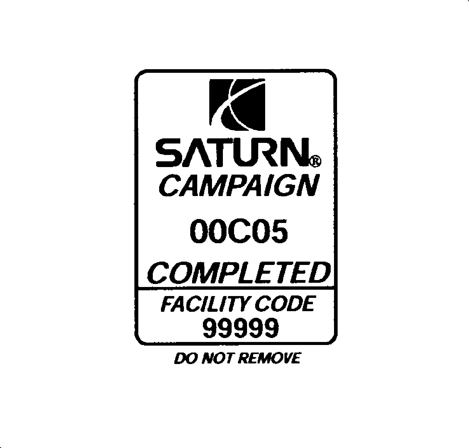
As a reminder, additional labels may be ordered from Saturn publications (1-800-828-2112, prompt 3, Item #S03 00013A for the Campaign Completion Label and Item #S03 00013B for the Clear Protective Cover ).
Credit
1. To receive credit for replacing the hazard warning switch assembly, submit a claim with the information below:
Repair Performed | Failed Part No. | Parts Allow. | Sale Type | Case Type | Labor Op | Labor Hours | Admin. Hours** |
|---|---|---|---|---|---|---|---|
Inspect Brake Pipe Fittings | N/A | * | WC | VC | V0382 | 0.4 | 0.1 |
Inspect Brake Pipe Fittings and Replace Brake Pipe(s) | 21013345 (R/Frt) | -- | WC | VC | V0383 | 0.4 | 0.1 |
21012546 (L/Frt) | |||||||
21013048 (R/Rear) | |||||||
21012542 (L/Rear) | |||||||
Add: | |||||||
A. To Replace Right Front Brake Pipe | -- | -- | -- | -- | -- | 0.8 | -- |
B. To Replace Left Front Brake Pipe | -- | -- | -- | -- | -- | 0.7 | -- |
C. To Replace Both Front Brake Pipes | -- | -- | -- | -- | -- | 0.9 | -- |
D. To Replace Right Rear Brake Pipe | -- | -- | -- | -- | -- | 1.1 | -- |
E. To Replace Left Rear Brake Pipe | -- | -- | -- | -- | -- | 1.1 | -- |
F. To Replace Both Rear Brake Pipes | -- | -- | -- | -- | -- | 1.2 | -- |
G. To Replace One Front Brake Pipe and One Rear Brake Pipe | -- | -- | -- | -- | -- | 1.3 | -- |
H. To Replace Both Front Brake Pipes and One Rear Brake Pipe | -- | -- | -- | -- | -- | 1.4 | -- |
I. To Replace One Front Brake Pipe and Both Rear Brake Pipes | -- | -- | -- | -- | -- | 1.4 | -- |
J. To Replace All Brake Pipes | -- | -- | -- | -- | -- | 1.5 | -- |
2. To receive credit for loaner/rental car costs incurred while owner awaits campaign repair or other goodwill expenses, submit a claim with the information below:
Repair Performed | Sale Type | Case Type | Labor Op | Net Item Amount | Net Item Code | # Days Rental |
|---|---|---|---|---|---|---|
Loaner Reimbursement | WC | VC | Z4054 | *** | C | **** |
Other/Goodwill | WC | VC | Z4055 | *** | R | N/A |
3. Retailers are empowered to use good judgement regarding loaner/rental cars or any other goodwill expenses deemed necessary. It will not be necessary to call the Saturn Customer Assistance Center for authorization of goodwill. The Goodwill Worksheet (printed towards the back of this bulletin) must be used to document goodwill expenses. The completed Goodwill Worksheet must be attached to the hard copy of the CSO. Retailers are to make sufficient copies of the blank Goodwill Worksheet to document goodwill expenses.
4. Check your Saturn SERVICELINE.XL Claim Memorandum daily. Remember to code the claim as a WC sale type and VC case type. Contact your field representative if you need assistance.
5. All labor operations claimed in this bulletin must be submitted on individual (unrelated) CSO lines. Refer to the Customer Service Order Preparation Manual for details on Product Campaign Claim Submission.
* The parts allowance should be the sum total of the current SSPO Retailer net price plus 30% of all parts required for the repair.
** Campaign administrative allowance.
*** Net amount must be submitted as a miscellaneous sale...Loaner reimbursement not to exceed $30/day.
**** Enter number of days vehicle was rented...Not to exceed 1 day.
00-C-05 GOODWILL WORKSHEET
As stated in the "Credit" section of this bulletin, Retailers are empowered to use good judgement regarding loaner/rental cars or other goodwill expenses that might become necessary for customer satisfaction.
Complete this worksheet and attach it to the hard copy of the Customer Service Order (CSO) to document all campaign goodwill claims submitted to Saturn.
VIN #
A. Vehicle Loaner/Rental Allowance Explanation: | $ | ||||
| |||||
| |||||
| |||||
Repair Performed | Sale Type | Case Type | Labor OP | Net Item Code | # Days Rental |
Loaner Reimbursement | WC | VC | Z4054 | C | * |
* Not to exceed $30/day for 1 day | |||||
| |||||
| |||||
| |||||
B. Other/Goodwill Allowance Explanation (Specify what was done and why): | $ | ||||
| |||||
| |||||
| |||||
Repair Performed | Sale Type | Case Type | Labor OP | Net Item Code | # Days Rental |
Other Goodwill | WC | VC | Z4055 | R | N/A |
| |||||
| |||||
| |||||
Authorized Retailer Signature | |||||
(Please copy this form as necessary) | |||||
Dear Saturn Owner:
This notice is sent to you in accordance with the requirements of the National Traffic and Motor Vehicle Safety Act.
Saturn has decided that certain 2000 model year S-Series vehicles fail to conform to the requirements of Federal Motor Vehicle Safety Standard (FMVSS) #135, "Passenger Car Brake Systems." These vehicles were produced with brake pipe attachment nuts that may not be tightened to specification. If the brake pipe nuts are not properly tightened, brake fluid leakage could occur. Continuing to operate the vehicle with brake fluid leaking may result in illumination of the red 'BRAKE' warning light on the instrument panel, and/or an increase in brake pedal travel. If this condition were to occur in a situation where stopping distances were minimal, a vehicle crash could occur.
What Saturn will do
We will inspect brake pipe nuts for leakage, verify they are tightened to specification, and replace brake pipes as needed at no charge to you. It will take less than two hours to make the repairs, although some additional time may be required for paperwork and processing.
What you should do
Contact your Saturn Retailer to arrange to have this service performed.
Your Retailer is prepared to perform this service promptly and with minimal inconvenience to you. However if your car is provided to the Retailer on the agreed service date and the condition is not remedied on that date, or within five days, please contact the Saturn Customer Assistance Center at 1-800-553-6000 prompt 3, or for the hearing impaired, 1-800-833-6000. We will assist you and the Retailer in getting your car serviced.
If, after contacting your Saturn Retailer and the Saturn Customer Assistance Center, you are still not satisfied that we have done our best to remedy this condition without charge and within a reasonable time, you may wish to write the Administrator, National Highway Traffic Safety Administration, 400 Seventh Street SW, Washington, DC 20590 or call 1-800-424-9393 (Washington, DC residents use 202-366-0123).
Again, we sincerely regret any inconvenience or concern this situation may cause you. We want you to know that we will do our best, throughout your ownership experience, to ensure that your Saturn provides you many miles of enjoyable driving.
Sincerely,
Saturn Corporation
00-C-05
