2000 Saturn S-Series Vehicles (All Models)

| Subject: | INSPECTION AND REINFORCEMENT OF INSTRUMENT PANEL CARRIER ASSEMBLY (IF NECESSARY) |
| Models: | 2000 SATURN S-SERIES VEHICLES (ALL MODELS) |
All Saturn Retailers and Authorized Service Providers
The Highway Safety Act, as amended, provides that each vehicle which is subject to a recall campaign of this type must be adequately repaired within a reasonable time after the customer has tendered it for repair. A failure to repair within sixty (60) days after tender of a vehicle is prima facie evidence of failure to repair within a reasonable time.
If the condition is not adequately repaired within a reasonable time, the customer may be entitled to an identical or reasonably equivalent vehicle at no charge or to a refund of the purchase price less a reasonable allowance for depreciation.
To avoid having to provide these burdensome remedies, every effort must be made to promptly schedule an appointment with each customer and to repair their vehicle as soon as possible. As you will see in reading the attached copy of the divisional letter that is being sent to customers, the customers are being instructed to contact the appropriate Customer Assistance Center if their dealer does not remedy the condition within five (5) days of the mutually agreed upon service date. If the condition is not remedied within a reasonable time, they are instructed on how to contact the National Highway Traffic Safety Administration.
Defect Involved
Saturn has decided that certain 2000 Model Year S-Series vehicles fail to meet the sled test performance requirement of Federal Motor Vehicle Safety Standard (FMVSS) #208, "Occupant Crash Protection". Some of these vehicles were manufactured with welds in the instrument panel carrier assembly that fail to meet Saturn's stringent quality standards. a front seat occupant, particularly an unbelted occupant, may have an increased risk of injury in a frontal crash.
Vehicles Involved
Only selected 2000 model year S-Series Saturn vehicles within the following VIN range will require this campaign:
YZ100005 - YZ105319
A VIN listing of the involved vehicles is included in this bulletin for your reference.
You must verify campaign involvement through your AS400 system, or with the listing attached to this bulletin. It is important to note that campaign claims will only be paid on involved vehicles.
Owner Notification
Owners of all involved vehicles will be notified of this campaign by Saturn. (Refer to the owner letter included in this bulletin.)
Facility VIN Listing
A list of vehicles assigned to you (Facility VIN Listing) , which our records indicate were sold by or shipped to you, (or are located in close proximity to your facility) is enclosed.
This listing contains:
| • | Owner's name with address and telephone number; |
| • | Complete vehicle identification number (VIN); and |
| • | VINs of vehicles which, according to Saturn records, are in route to your Retailer or already in retail stock. |
The Facility VIN Listing (with owner information) is furnished to involved Retailers with the Product Campaign Bulletin. Although these vehicles are assigned to your facility, it is important to note that owners may elect to have their vehicle serviced at the Saturn Retail Facility of their choice.
Those Retailers not involved initially in this campaign will receive a message at the top of a blank Facility VIN Listing that states: NO VEHICLES ASSIGNED AT THIS TIME FOR CAMPAIGN 00C04.
These listings may contain owner names and addresses obtained from State Motor Vehicle Registration Records. The use of such motor vehicle registration data for any other purpose is a violation of law in several states. Accordingly, you are urged to limit the use of this listing to the follow-up necessary to complete this campaign. Those records updated with California DMV registration information will have the following message printed adjacent to the appropriate VIN: "OWNER INFORMATION UPDATED BY CALIFORNIA DMV; PUBLICATION PROHIBITED."
Retailer Responsibility
All unsold vehicles in Retailers' possession and subject to this campaign must be held at the retail facility and repaired per the service procedure of this campaign bulletin before owners take possession of these vehicles.
Retailers are to service all vehicles subject to this campaign at no charge to owners, regardless of mileage, age of vehicle, or ownership, from this time forward.
Owners of vehicles recently sold from your vehicle inventory are to be contacted by the Retailer and arrangements made to make the required correction according to the procedure contained in this bulletin.
In summary, whenever a vehicle subject to this campaign enters your vehicle inventory, or is in your retail facility for service in the future, please take the steps necessary to be sure the campaign correction has been made before selling or releasing the vehicle.
Transfer of Campaign Responsibility
Saturn vehicles that have been sold by you, which may be closer in proximity to another Saturn Retailer, may still appear on your Facility VIN Listing. If either you or the vehicle owner determines that it is more desirable for a vehicle on your Facility VIN Listing to be serviced by another Saturn Retailer, or if the customer's address has recently changed, campaign responsibility may be transferred by completing the following:
| • | Submit a Campaign Vehicle Action Report to your Customer Assistance Manager (CAM) at the Saturn Customer Assistance Center; OR |
| • | Submit an update in owner information to the Saturn Owner of Record system, via SERVICELINE XL, for Saturn Customer Assistance Center review and approval. |
A copy of the Campaign Vehicle Action Report is included for your reference. Additional copies can be ordered from Saturn Publications (1-800-828-2112, prompt 3, Item # S0397050 ). All changes to campaign responsibility will be reflected in your next Unfixed VIN Report.
All other changes in vehicle status (e.g., scrapped, stolen, etc.) are to be made in accordance with section 4.4.3 of the Retailer Service Reference Guide, "Notifying Saturn of Vehicle Status Change."
Parts Information
- A pre-shipment of structural fasteners required to perform this campaign has been automatically sent to you from Saturn Service Parts Operations (SSPO). These initial shipments are to aid the Retailer in campaign preparation and ensure minimal customer inconvenience.
- Should you require any additional parts, please order as needed.
- Required Part:
Part Number | Description | Quantity Required Per Vehicle |
|---|---|---|
21127002 | Structural Fastener | 2 |
Suggestions for Ensuring Customer Satisfaction
As you know, Saturn's success hinges upon our ability to execute superior customer support throughout the ownership experience, especially when important corrective actions such as this are required.
It is imperative that every effort is made to accommodate the affected owners. Additionally, priority should be given to customer vehicles over retail inventory vehicles. If you have any questions, please coordinate with the Saturn Customer Assistance Center to help ensure customer satisfaction.
Instrument Panel Carrier Assembly Inspection and/or Reinforcement Procedure
Materials Needed
| • | 3/8 Inch Right Angle Drill Motor (provided) |
| • | Hand-Held Hydraulic Rivet Tool (provided) |
| • | 1/8 Inch and 1/4 Inch Drill Bits (2 of each provided) |
- Disconnect negative battery cable.
- Turn the steering wheel so that the vehicle's wheels are pointing straight ahead.
- Turn the ignition switch to LOCK and remove the key.
- Remove the AIR BAG fuse from the instrument panel fuse block (IPFB)
- Disconnect the drive yellow two-way connector; clipped to the steering column brace.
- Detach the clip holding the passenger yellow two-way connector to the metal brace, near the HVAC fan.
- Disconnect passenger yellow two-way connector.
- Remove left endcap assembly:
- Gently pry the edges of the ignition lock bezel with a blunt tool and remove the bezel from the lower shroud.
- Remove the steering column upper shroud:
- Remove the dimmer/traction control switch assembly:
- Remove the I/P cluster bezel. Disengage the clips from the retainer assembly by grasping the edges of the bezel near the clip locations and pulling outward.
- Remove the radio:
- Inspect the I/P carrier assembly at the locations indicated in the illustration views A and B for structural fasteners already being installed.
- Remove the HVAC controller.
- Cover the IPFB and the surrounding area with shop rags to collect the metal shavings.
- Using a right angle drill and drill bit, drill 1/8 in pilot holes in the following locations:
- Using the right angle drill and drill bit provided, final drill both pilot holes to the proper diameter of 1/4 in.
- Install a structural fastener (P/N 21127002) into the drilled hole. Use the rivet tool to compress the structural fastener until the compression stud pops free.
- Vacuum any metal shavings from the area repair and carefully remove the covering on the IPFB, ensuring that no metal shavings fall free.
- Install the HVAC controller:
- Install the radio.
- Install the I/P cluster bezel.
- Install the upper steering column shroud.
- Install the ignition bezel.
- Connect the dimmer/traction control switch assembly connectors.
- Install the dimmer/traction control switch assembly into the bezel opening.
- Install the left endcap assembly.
- Connect the passenger yellow two-way connector.
- Attach the connector clip to the metal brace near the HVAC fan.
- Connect the driver yellow two-way connector and clip to the steering column brace.
- Install the AIR BAG fuse in the IPFB.
- Connect the negative battery cable.
- Verify the following are operating properly:
Caution: When you are performing service on or near SIR components or SIR wiring, you must disable the SIR system. Failure to follow the correct procedure could cause air bag deployment, personal injury, or unnecessary SIR system repairs.
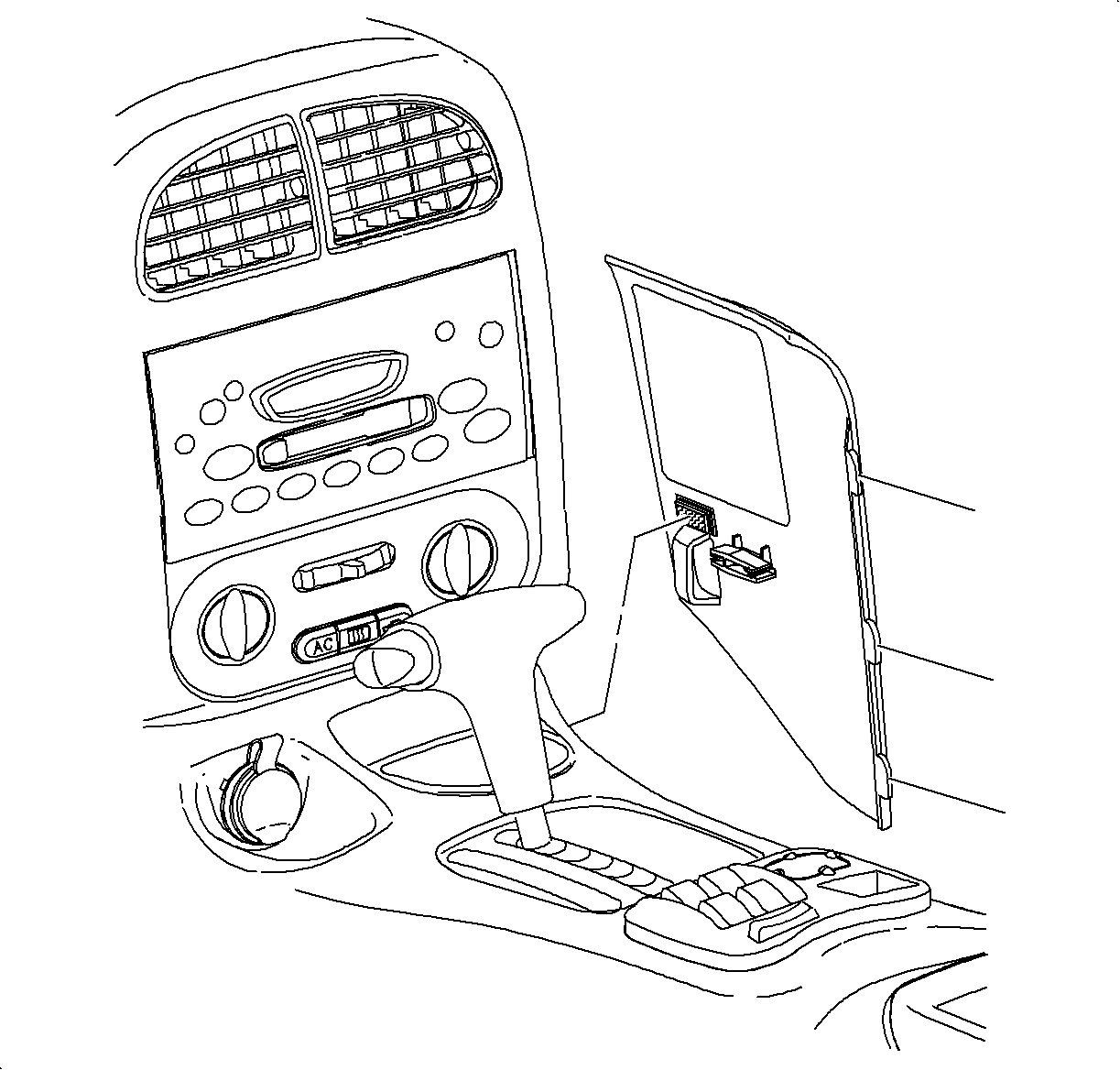
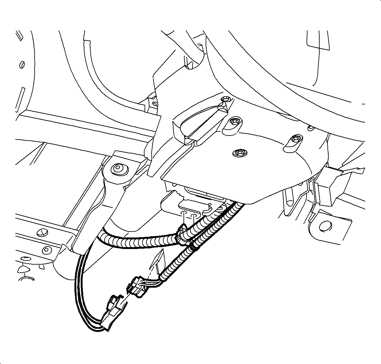
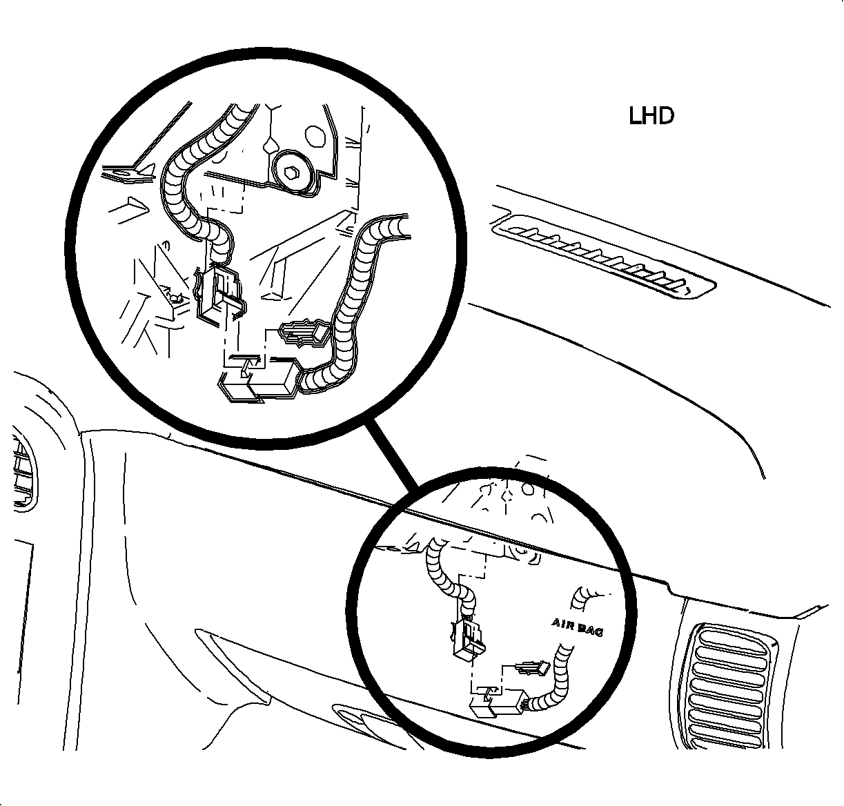
Important: Do not remove the upper trim panel. The passenger disconnect is accessible from the underside of the I/P.

Notice: Do not remove door primary weatherstrip. Adhesion will be lost if removed.
| 8.1. | Remove the screws. |
| 8.2. | Carefully disengage the endcap clips at the I/P retainer locations. Use a blunt tool to disengage the clips. |
| 8.3. | Maneuver the endcap assembly past the inner I/P retainer assembly and the weatherstrips. |
| 8.4. | Disconnect the left door jamb switch connector by disengaging the retaining tabs on the connector. |
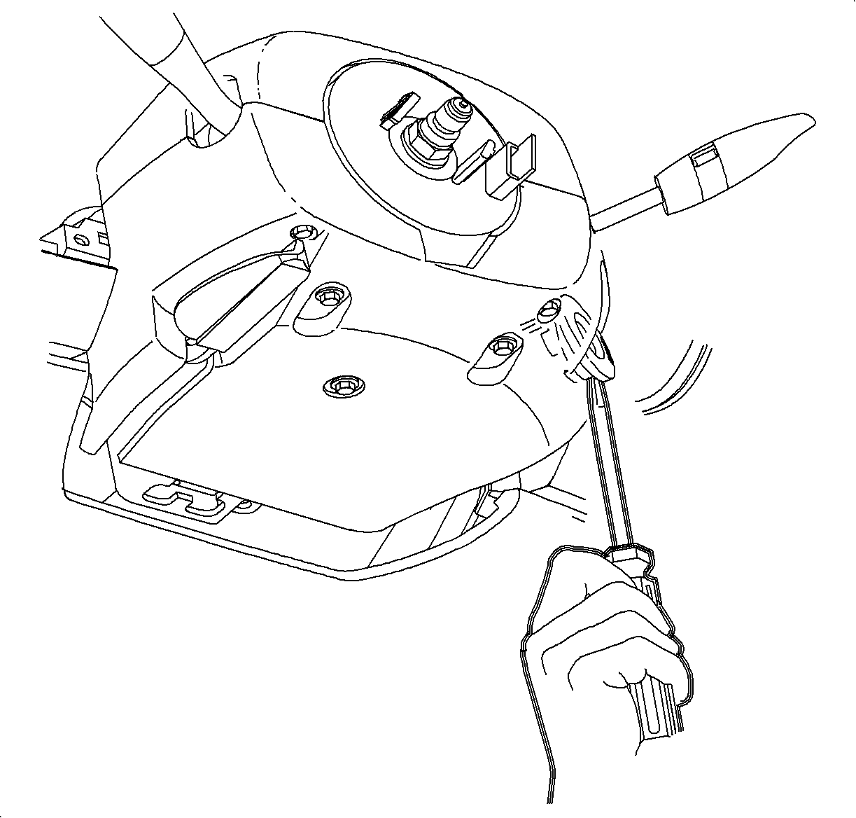

| 10.1. | Remove two screws from the long recessed holes in the lower steering column shroud. |
| 10.2. | Lower the steering column by pushing down on the steering column adjusting handle. |
| 10.3. | Lift and remove the upper shroud from the steering column. |

| 11.1. | Use a blunt tool to pry and depress the retaining tab on the left side of the switch housing. |
| 11.2. | Depress the wiring connector tabs and remove the connectors from the switch. |

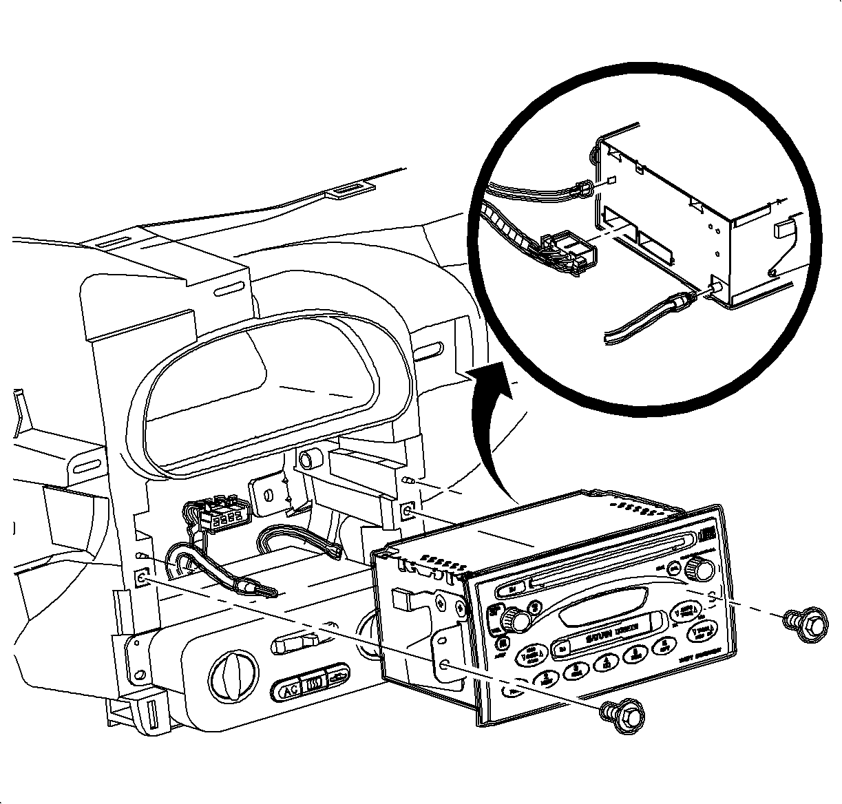
| 13.1. | Remove the radio screws. |
| 13.2. | Pull the radio out slightly to access the rear. |
| 13.3. | Disconnect the electrical connector, the antenna lead, and the ground strap spade terminal. |
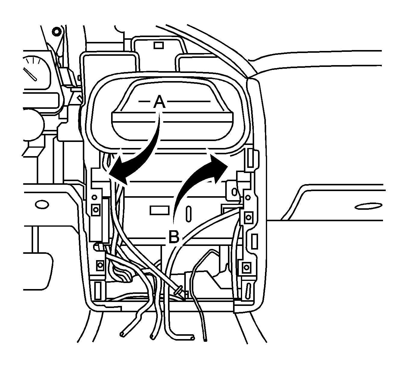
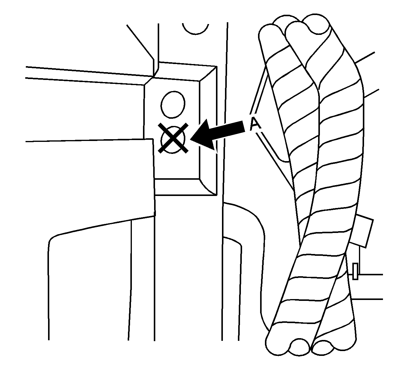
| • | If the structural fasteners are already installed , go to step 22. |
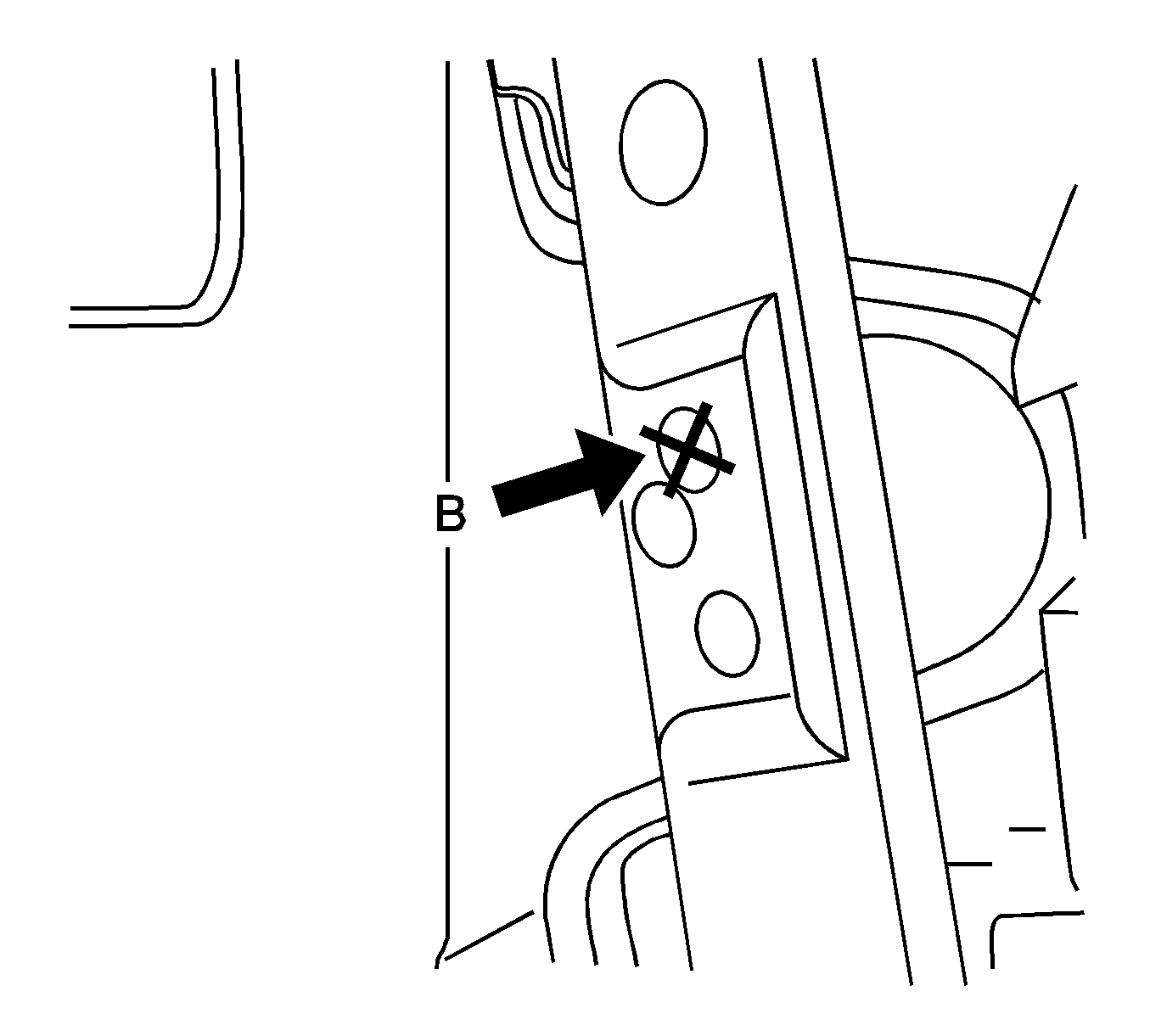
| • | If the structural fasteners are not already installed , continue with the next step. |
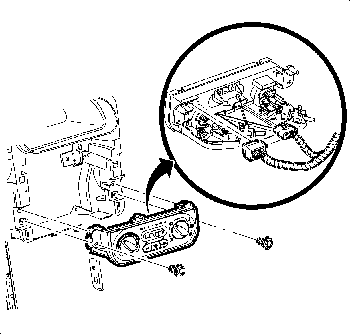
| 15.1. | Remove the screws. |
| 15.2. | Disconnect the HVAC blower switch connector. |
| 15.3. | Disconnect the HVAC controller connector. |

| Notice: When removing the HVAC control cables, only pull at the coiled ends of the cable. Do NOT pull on the straight wire section of the cable. If the straight wire section of the cable is damaged or bent, effort required to rotate the control knobs will increase. |
| 15.4. | Remove the temperature control cable by squeezing the lock tabs together while pulling the coiled end of the cable straight up beyond the retaining tabs. |
| 15.5. | Remove the mode control cable by squeezing the lock tabs together while pulling the coiled end of the cable straight up beyond the retaining tabs. |

Important: Covering the instrument panel fuse block (IPFB) is critical to prevent the possibility of metal shavings causing shorts at the IPFB connections.

| • | The left H-brace support between the two spot weld locations as indicated in View A: Left H-Brace. |

| Important: The following hole location is critical for a proper repair. All 3 layers of metal at the H-brace support location must be retained by the structural fastener. |
| • | The right H-brace support in the upper rear corner of the stamping as indicated in View A: Right H-Brace. |
Important: When compressing the structural fastener, you may have to release the rivet tool and grip lower on the compression stud.

Notice: When installing the HVAC control cables, only push at the coiled ends of the cable. Do not push on the straight wire section of the cable. If the straight wire section of the cable is damaged or bent, effort required to rotate the control knobs will increase.
Important: Make sure the wiring harnesses do not interfere with the control lever movement.
Cable Identification:
| • | Temperature control cable -- white |
| • | Mode control cable -- black |

| 21.1. | Install the mode control cable onto the mode control pin. |
| 21.2. | Snap the slot on the cable into the HVAC controller base. |
| 21.3. | Install the temperature control cable onto the temperature control pin. |
| 21.4. | Snap the slot on the cable into the HVAC controller base. |
| 21.5. | Install the HVAC blower switch connector. |
| 21.6. | Install the HVAC controller connector. |
| 21.7. | Install and tighten screws. |
Tighten
Tighten the screws to 1.5 N·m (13 lb in).

| 22.1. | Connect the radio ground strap spade terminal. |
| 22.2. | Connect the electrical connector. |
| 22.3. | Connect the antenna lead. |
| 22.4. | Install the radio by sliding it into the guides on the instrument panel. |
| 22.5. | Install and tighten the screws. |
Tighten
Tighten the screws to 2.5 N·m (22 lb in).

| 23.1. | Place the dimmer/traction control switch assembly connectors through the bezel opening. |
| 23.2. | Position the I/P cluster bezel by lining up the clip locations. |
| 23.3. | Snap the I/P cluster bezel in place by pushing at the clip locations. |
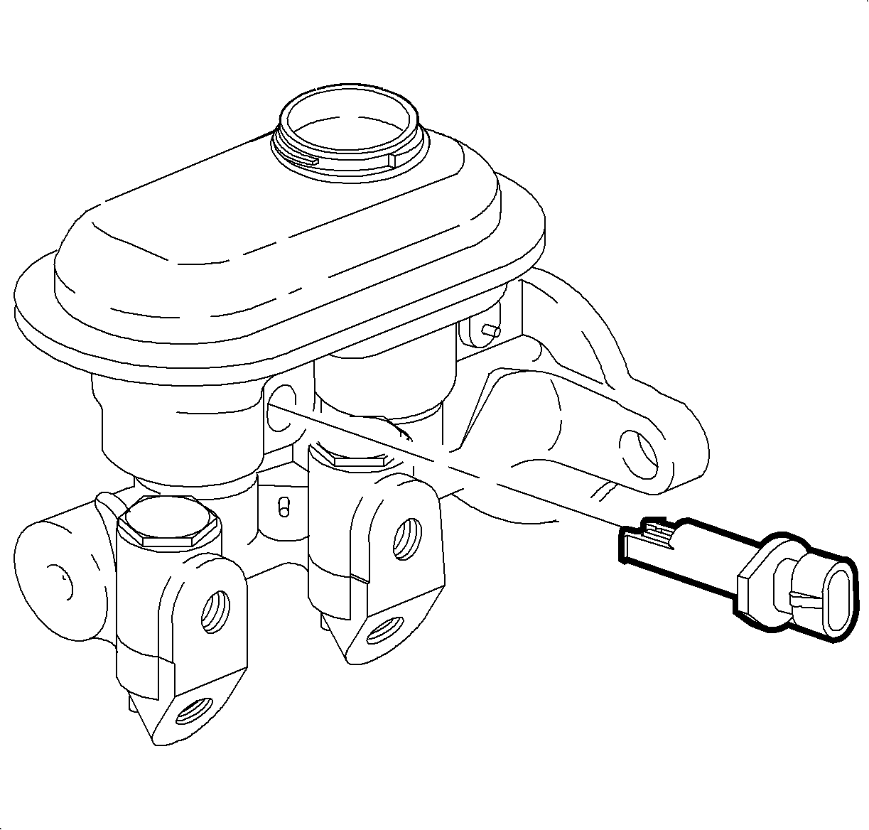
| 24.1. | Position the upper steering column shroud. |
| 24.2. | Raise the steering column by pushing down on the steering column adjusting handle. |
| 24.3. | Install two retaining screws in the long recessed holes in the lower steering column shroud. |
Tighten
Tighten the screws to 1.5 N·m (13 lb in).
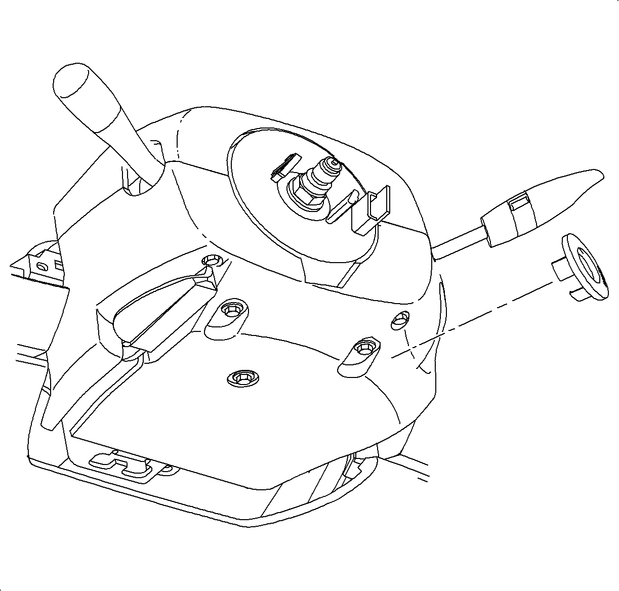
| • | Align the peg of the ignition bezel with the cut out in the lower shroud. |
| • | Snap the bezel into place. |
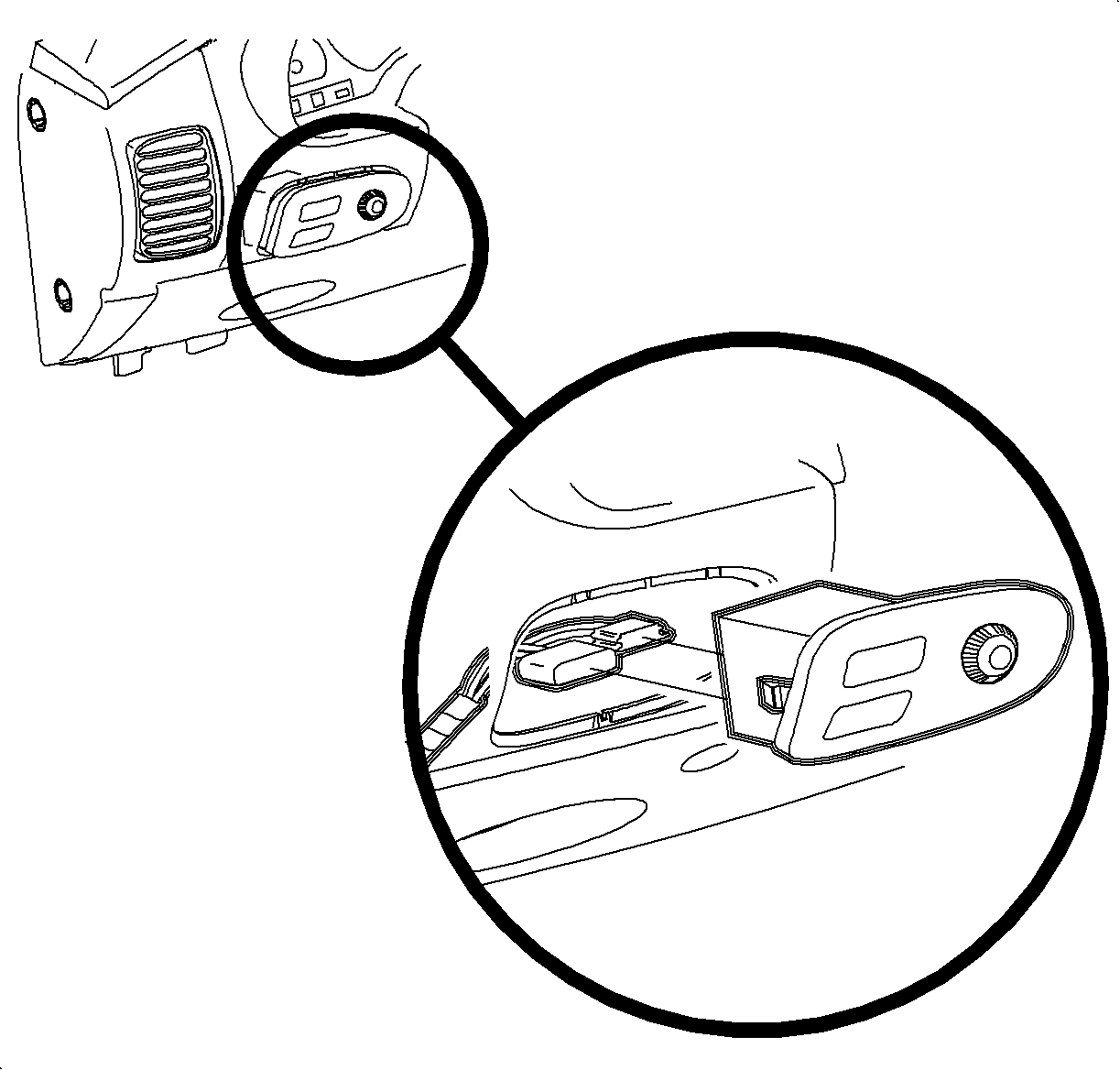

Important: Ensure that the endcap bottom portions are inside the I/P filler panel.
| 28.1. | Connect the left door jamb switch connector. |
| 28.2. | Maneuver the endcap past the inner I/P retainer assembly and the door primary weatherstrip. |
| 28.3. | Snap the clips into the I/P retainer assembly locations. |
| 28.4. | Install the screws. |
Tighten
Tighten the screws to 2.2 N·m (19 lb in).


Tighten
Tighten the battery cable screw to 17 N·m
(33 lb ft).
| • | The AIR BAG telltale |
| • | The HVAC controls |
| • | The radio |
| • | The dimmer switch |
| • | The traction control switch, if equipped |
Campaign Completion Label
Upon completion of the campaign, a Campaign Identification Label and a Clear Protective Cover should be affixed on a clean, dry surface of the radiator core support in an area clearly visible when the hood is raised. Each label provides a space to print in ink (or type) the campaign number (00C04) and the five (5) digit facility code of the Retailer performing the campaign service.
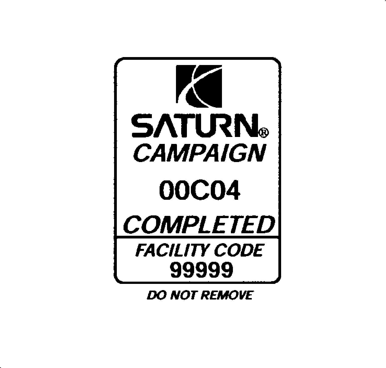
As a reminder, additional labels may be ordered from Saturn publications (1-800-828-2112, prompt 3, Item #S03 00013A for the Campaign Completion Label and Item #S03 00013B for the Clear Protective Cover ).
Credit
1. To receive credit for inspecting and reinforcing the instrument panel carrier assembly (if necessary), submit a claim with the information below:
Repair Performed | Part No. | Parts Allow. | Sale Type | Case Type | Labor Op | Labor Hours | Admin. Hours** |
|---|---|---|---|---|---|---|---|
Inspect for Structural Fasteners in Instrument Panel Carrier Assembly | N/A | * | WC | VC | V0377 | 0.6 | 0.1 |
Add: | |||||||
A. To Install Structural Fasteners in Instrument Panel Carrier Assembly | 21127002 | -- | -- | -- | -- | 0.5 | -- |
2. To receive credit for loaner/rental car costs incurred while owner awaits campaign repair or other goodwill expenses, submit a claim with the information below:
Repair Performed | Sale Type | Case Type | Labor Op | Net Item Amount | Net Item Code | # Days Rental |
|---|---|---|---|---|---|---|
Loaner Reimbursement | WC | VC | Z4049 | *** | C | **** |
Other/Goodwill | WC | VC | Z4050 | *** | R | N/A |
3. Retailers are empowered to use good judgement regarding loaner/rental cars or any other goodwill expenses deemed necessary. It will not be necessary to call the Saturn Customer Assistance Center for authorization of goodwill. The Goodwill Worksheet (printed towards the back of this bulletin) must be used to document goodwill expenses. The completed Goodwill Worksheet must be attached to the hard copy of the CSO. Retailers are to make sufficient copies of the blank Goodwill Worksheet to document goodwill expenses.
4. Check your Saturn SERVICELINE.XL Claim Memorandum daily. Remember to code the claim as a WC sale type and VC case type. Contact your field representative if you need assistance.
5. All labor operations claimed in this bulletin must be submitted on individual (unrelated) CSO lines. Refer to the Customer Service Order Preparation Manual for details on Product Campaign Claim Submission.
* The parts allowance should be the sum total of the current SSPO Retailer net price plus 30% of all parts required for the repair.
** Campaign administrative allowance.
*** Net amount must be submitted as a miscellaneous sale...Loaner reimbursement not to exceed $30/day.
**** Enter number of days vehicle was rented...Not to exceed 1 day.
00-C-04 GOODWILL WORKSHEET
As stated in the "Credit" section of this bulletin, Retailers are empowered to use good judgement regarding loaner/rental cars or other goodwill expenses that might become necessary for customer satisfaction.
Complete this worksheet and attach it to the hard copy of the Customer Service Order (CSO) to document all campaign goodwill claims submitted to Saturn.
VIN #
A. Vehicle Loaner/Rental Allowance Explanation: | $ | ||||
| |||||
| |||||
| |||||
Repair Performed | Sale Type | Case Type | Labor OP | Net Item Code | # Days Rental |
Loaner Reimbursement | WC | VC | Z4049 | C | * |
* Not to exceed $30/day for 1 day | |||||
| |||||
| |||||
| |||||
B. Other/Goodwill Allowance Explanation (Specify what was done and why): | $ | ||||
| |||||
| |||||
| |||||
Repair Performed | Sale Type | Case Type | Labor OP | Net Item Code | # Days Rental |
Other Goodwill | WC | VC | Z4050 | R | N/A |
| |||||
| |||||
| |||||
Authorized Retailer Signature | |||||
(Please copy this form as necessary) | |||||
Dear Saturn Owner:
This notice is sent to you in accordance with the requirements of the National Traffic and Motor Vehicle Safety Act.
Saturn has decided that certain 2000 model year S-Series vehicles may fail to meet the sled test performance requirements of Federal Motor Vehicle Safety Standard 208, "Occupant Crash Protection." Some of these vehicles were manufactured with welds in the instrument panel carrier assembly that fail to meet Saturn's stringent quality standards. A front seat occupant, particularly an unbelted occupant, may have an increased risk of injury in a frontal crash.
What Saturn will do
We will repair your vehicle's instrument panel carrier assembly at no charge to you. It will take approximately 1½ hours to make the repairs, although some additional time may be required for paperwork and processing.
What you should do
Contact your Saturn Retailer to arrange to have this service performed.
Your Retailer is prepared to perform this service promptly and with minimal inconvenience to you. However if your car is provided to the Retailer on the agreed service date and the condition is not remedied on that date, or within five days, please contact the Saturn Customer Assistance Center at 1-800-553-6000 prompt 3, or for the hearing impaired, 1-800-833-6000. We will assist you and the Retailer in getting your car serviced.
If, after contacting your Saturn Retailer and the Saturn Customer Assistance Center, you are still not satisfied that we have done our best to remedy this condition without charge and within a reasonable time, you may wish to write the Administrator, National Highway Traffic Safety Administration, 400 Seventh Street SW, Washington, DC 20590, or call 1-800-424-9393 (Washington, DC residents use 202-366-0123).
Again, we sincerely regret any inconvenience or concern this situation may cause you. We want you to know that we will do our best, throughout your ownership experience, to ensure that your Saturn provides you many miles of enjoyable driving.
Sincerely,
Saturn Corporation
00-C-04
