SMU for All 2000 S Series Automatic Transaxle Service Manuals Regarding DTCs P0731, P0732, P0733, P0734, and P0741

| Subject: | Service Manual Update for the 2000 S-Series Automatic Transaxle Service Manual Regarding DTC P0731, P0732, P0733, P0734, and P0741 |
| Models: | 2000 Saturn S-Series Vehicles |
Purpose
The purpose of this bulletin is to update all the 2000 S-Series Automatic Transaxle Service Manuals at your location.
Obtain all the 2000 S-Series Automatic Transaxle Service Manuals at your location and update as indicated below.
Cross out the following pages with a marker or pen:
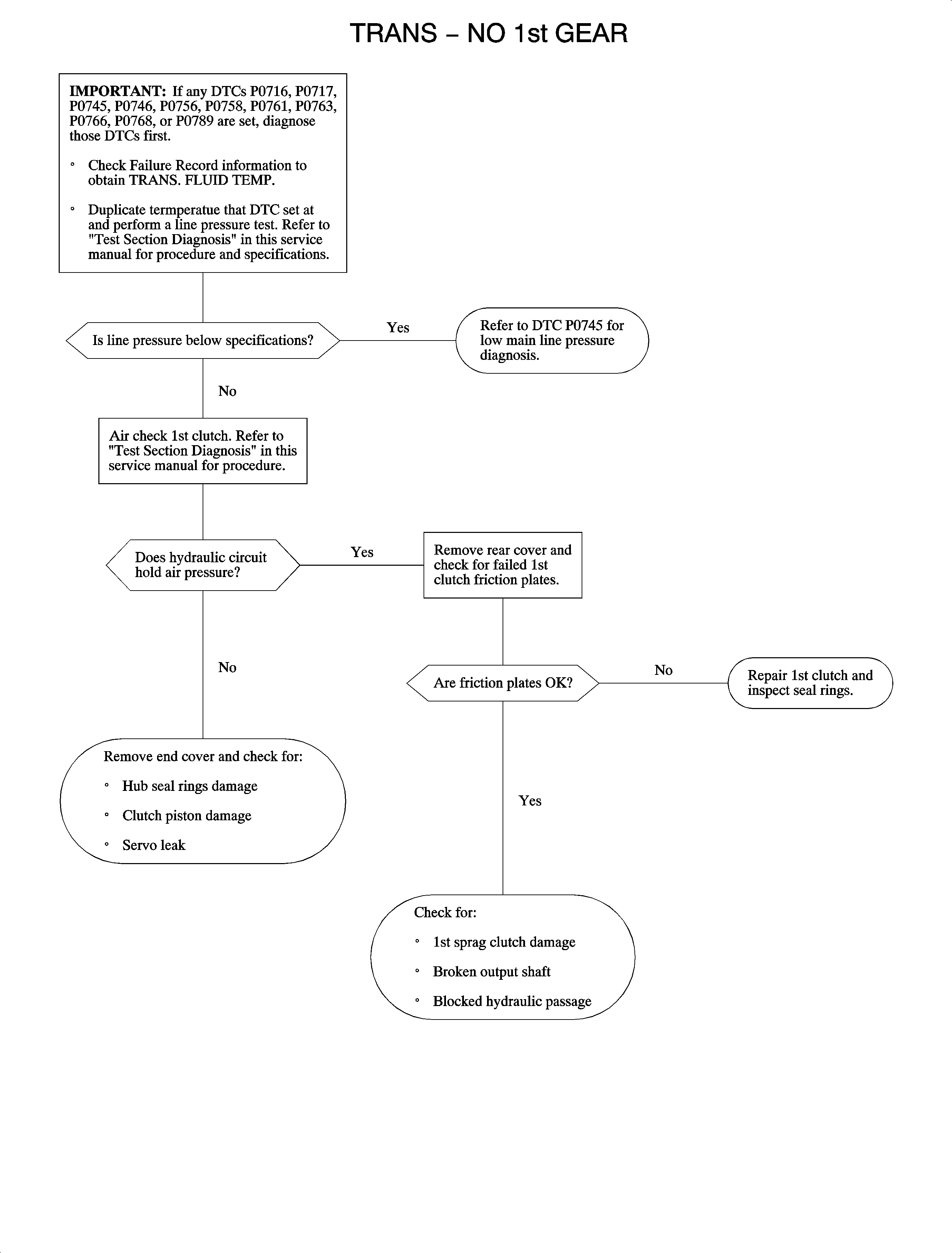
| • | 140 and 141 for DTC P0731 - Trans - No 1st Gear |
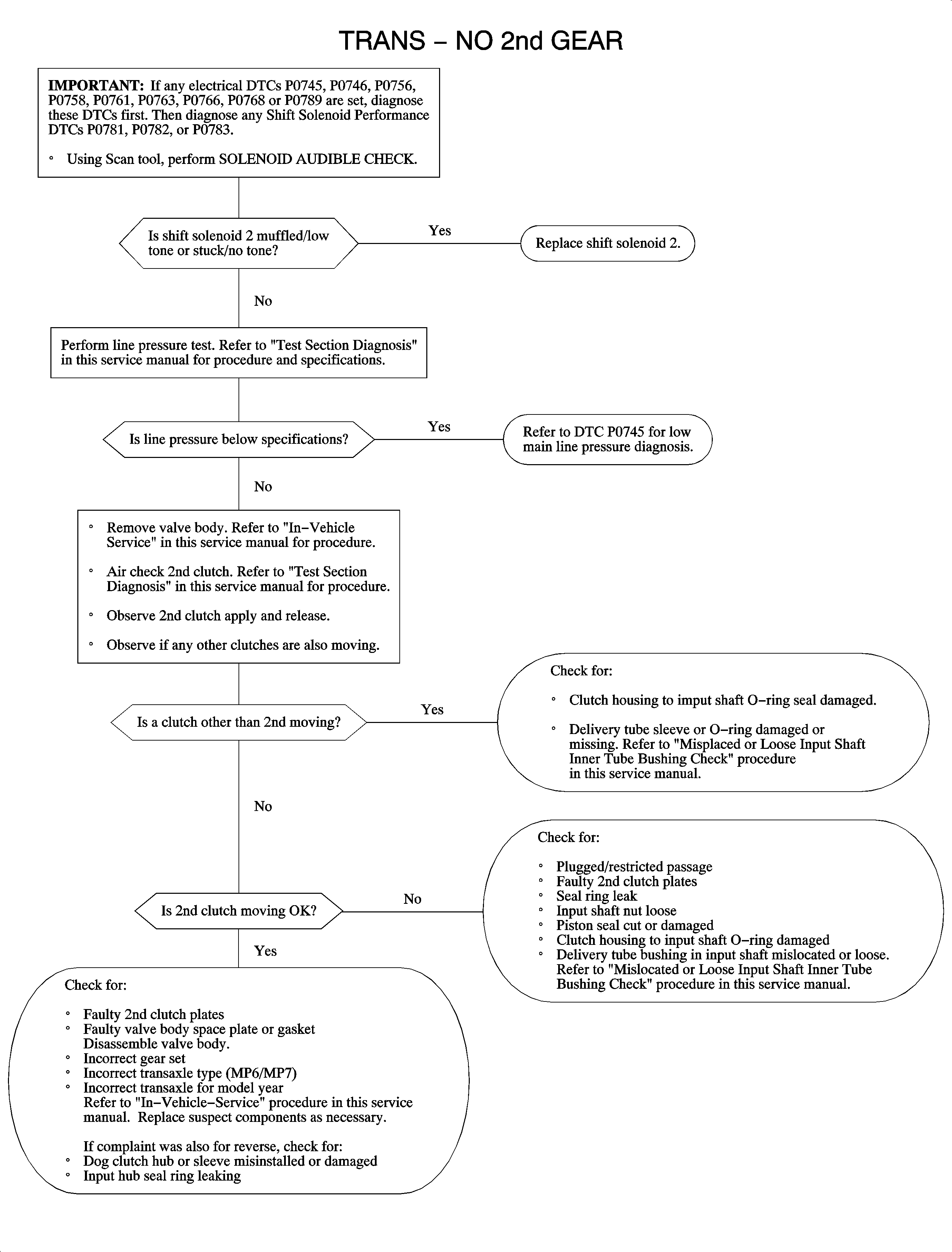
| • | 142 and 143 for DTC P0732 - Trans - No 2nd Gear |
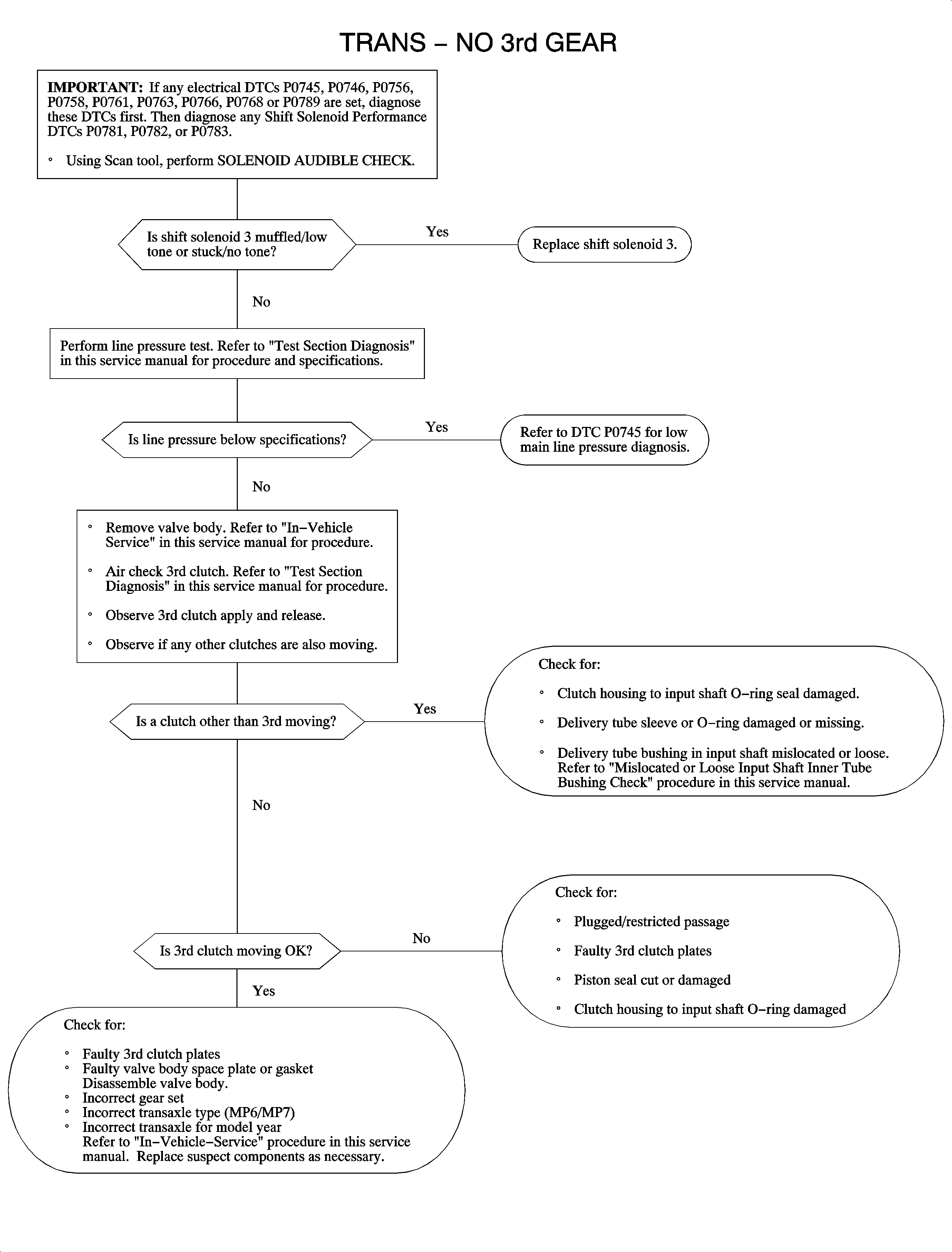
| • | 144 and 145 for DTC P0733 - Trans - No 3rd Gear |
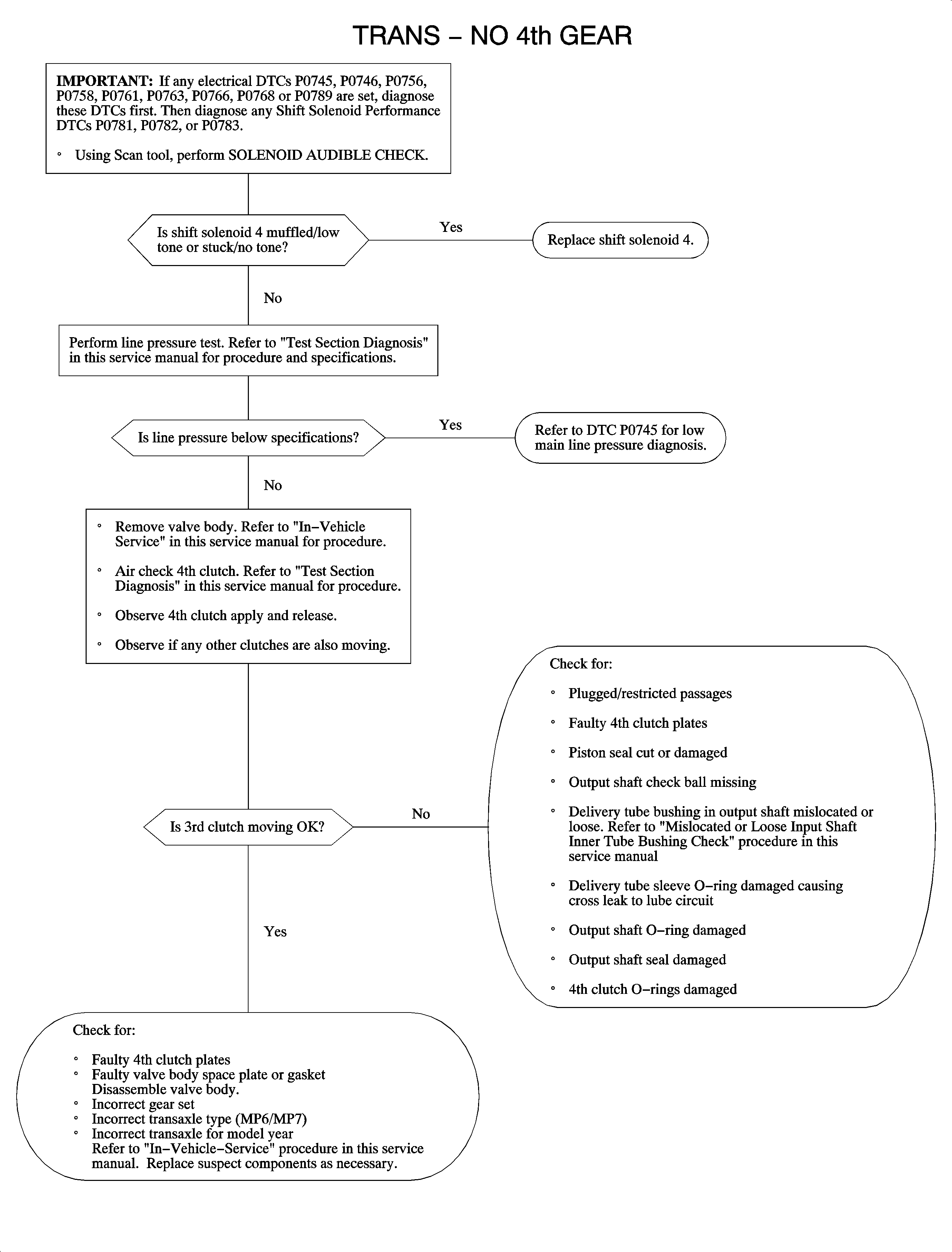
| • | 146 and 147 for DTC P0734 - Trans - No 4th Gear |
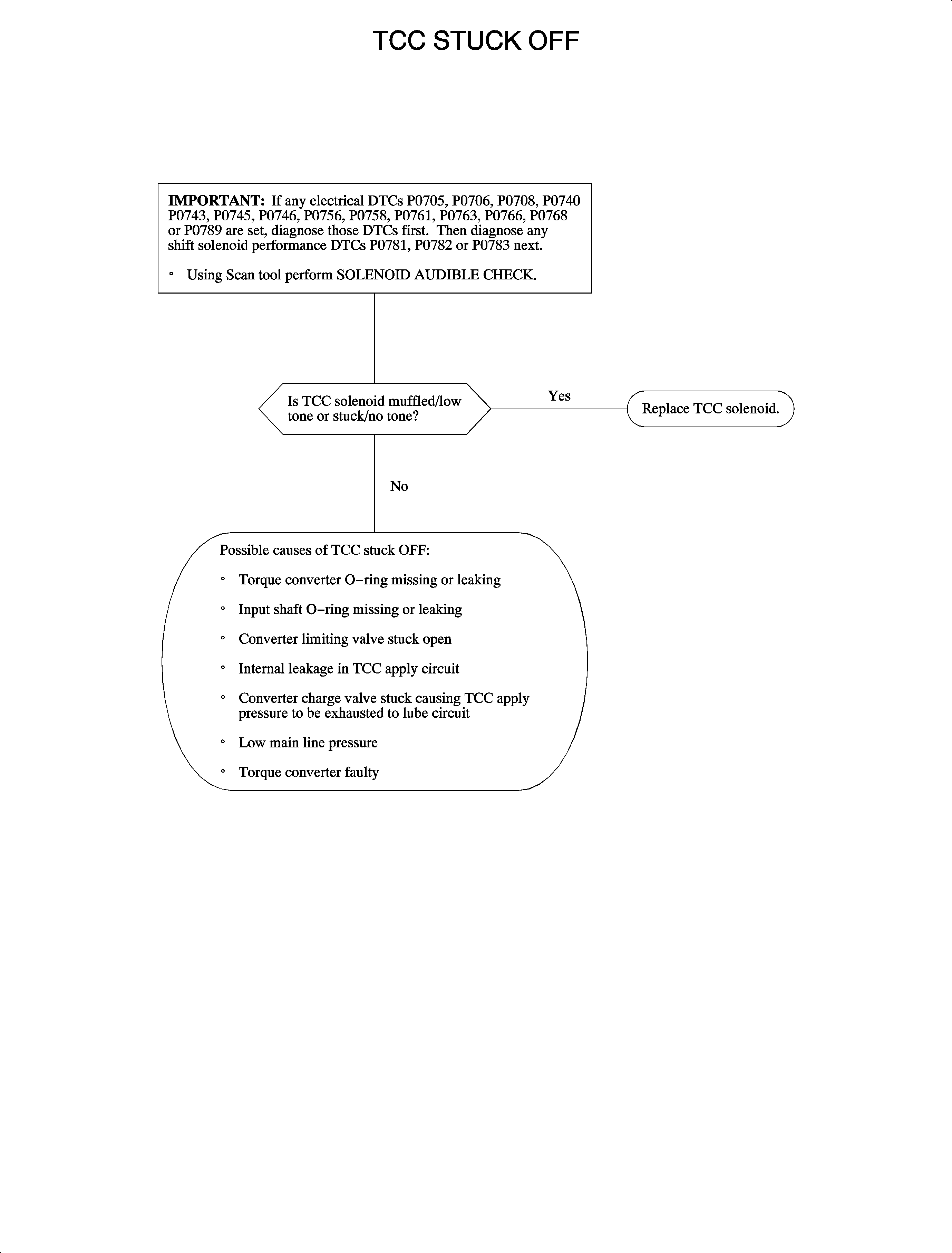
| • | 150 and 151 for DTC P0741 - TCC System Stuck Off |
DTC P0731 - Trans - No 1st Gear
The powertrain control module (PCM) uses the crankshaft position (CKP) sensor, input speed sensor (ISS) and output speed sensor (OSS) to determine engine speed, input shaft speed and output shaft speed. These sensor readings are used to determine the current gear ratio and RPM slip across the torque converter. The PCM uses this information from the sensors to determine if the commanded gear matches the actual gear. During normal driving conditions, the PCM will adapt main line pressure via the pressure control (PC) solenoid to prevent slipping and harsh shifts. First gear clutch is fed fluid directly from the manual valve and is applied in all forward gears. DTC P0731 sets when 1st clutch still slips after the PCM has commanded high main line pressure.
DTC Parameters
DTC P0731 will set if the PCM detects an incorrect actual 1st gear ratio when 1st gear is commanded ON when:
| • | The condition exists twice in one ignition cycle |
| • | A high main line pressure has been commanded |
| • | The transaxle is in a forward gear |
| • | The input speed is greater than 224 RPM. |
| • | The vehicle speed is greater than 5 km/h (3 mph) |
| • | The steady state ratio fail counter equals 255 for an in-gear failure, or the shift fail counter is greater than 100 on a downshift to 1st during acceleration (128=0 or normal operation) |
OR
| • | The condition exists twice in one ignition cycle |
| • | The second gear must be commanded ON for the vehicle to move. |
Diagnostic Aids
Important: If input speed sensor DTCs P0716 or P0717 are present, diagnose those DTCs first. These codes can cause a DTC P0731 to set.
Important: If DTC P0745, P0746, P0756, P0758, P0761, P0763, P0766, P0768, or P0789 is set, diagnose that DTC first. A diagnosed PC solenoid, shift solenoid 2, 3 or 4 low/high circuit fault DTC may have caused DTC P0731 to set.
Important: If any shift solenoid performance DTCs P0781, P0782, or P0783 (2nd , 3rd or 4th gear stuck On) are set, diagnose the highest gear first. A gear stuck On will cause no 1st gear.
Refer to "Test Section Diagnosis" for pressure apply points and for the following component/location description.
Possible causes of no 1st gear ratio:
| • | The end cover first gear hub seal rings damaged |
| • | 1st clutch piston leaking |
| • | The input shaft feed tube to end cover blocked |
| • | The servo leaking or passages blocked causing no oil pressure to 1st clutch |
| • | 1st gear sprag failed |
| • | 1st gear clutch plates worn |
Verify VSS and TRANSMISSION ISS read correctly on Scan tool.
Make sure the pressure control, shift 2, shift 3 and shift 4 solenoids are not intermittently sticking. Sticking solenoids may cause 2nd , 3rd or 4th gear to be applied from an initial start causing no 1st gear. Audible sound should be similar for all solenoids. A muffled tone indicates the need for replacement.
Important: 1st gear is a mechanical hydraulic apply. Other than line pressure, there is no electrical circuit for 1st gear.
DTC P0732 - Trans - No 2nd Gear
The powertrain control module (PCM) uses the crankshaft position (CKP) sensor, input speed sensor (ISS) and output speed sensor (OSS) to determine engine speed, input shaft speed and output shaft speed. These sensor readings are used to determine the current gear ratio and RPM slip across the torque converter. The PCM uses this information from the sensors to determine if the commanded gear matches the actual gear. During normal driving conditions, the PCM will adapt main line pressure via the pressure control (PC) solenoid to prevent slipping and harsh shifts. Shift solenoid 2 is used to apply or release second gear clutch. The PCM controls 2nd gear by controlling the ground for shift solenoid 2. The PCM will turn the solenoid Off (open the driver circuit) when second gear is commanded On to apply 2nd clutch. Shift solenoid 2 is supplied ignition voltage from the fuel pump relay whenever the PCM commands the fuel pump relay On. DTC P0732 sets when 2nd clutch still slips after the PCM has commanded high main line pressure.
DTC Parameters
DTC P0732 will set if the PCM detects an incorrect actual 2nd gear ratio when 2nd gear is commanded On when:
| • | The condition exists twice in one ignition cycle |
| • | The high main line pressure has been commanded |
| • | The transaxle is in a forward gear |
| • | The input speed is greater than 224 RPM |
| • | The vehicle speed is greater than 5 km/h (3 mph) |
| • | The steady state ratio fail counter equals 255 for an in-gear failure, or the shift fail counter is greater than 100 on a downshift or upshift to 2nd gear (128=0 or normal operation) |
DTC P0732 diagnostic runs continuously once the above conditions have been met.
DTC P0732 is a type A DTC
Diagnostic Aids
Important: If DTCs P0745, P0746, P0756, P0758, P0761, P0763, P0766, P0768 or P0789 is set, diagnose that DTC first. A diagnosed PC solenoid, shift solenoid 2, 3 or 4 low/high circuit fault DTC may have caused DTC P0732 to set.
Important: If any shift solenoid performance DTCs P0782 or P0783 3rd or 4th gear stuck On) are set, diagnose the highest gear first. A 3rd or 4th gear stuck On may cause no 2nd gear.
Refer to "Test Section Diagnosis" for pressure apply points and for the following component/location description.
Possible causes of no 2nd gear are listed in the flowchart on the succeeding page.
Verify VSS and TRANSMISSION ISS read correctly on Scan tool.
Make sure the pressure control, shift 2, shift 3 and shift 4 solenoids are not intermittently sticking. Sticking shift solenoid 3 or 4 may cause 3rd or 4th gear to be applied from an initial start causing no 2nd gear. Audible sound should be similar for all solenoids. A muffled tone indicates the need for replacement.
Important: There are different cases and different fwd/rev servo pistons for different model years. Incorrect use of these parts may result in no 2nd gear.
DTC P0733 - Trans - No 3rd Gear
The powertrain control module (PCM) uses the crankshaft position (CKP) sensor, input speed sensor (ISS) and output speed sensor (OSS) to determine engine speed, input shaft speed and output shaft speed. These sensor readings are used to determine the current gear ratio and RPM slip across the torque converter. The PCM uses this information from the sensors to determine if the commanded gear matches the actual gear. During normal driving conditions, the PCM will adapt main line pressure via the pressure control (PC) solenoid to prevent slipping and harsh shifts. Shift solenoid 3 is used to apply or release third gear clutch. The PCM controls 3rd gear by controlling the ground for shift solenoid 3. The PCM will turn the solenoid OFF, open the driver circuit, when 3rd gear is commanded On to apply 3rd clutch. Shift solenoid 3 is supplied ignition voltage from the fuel pump relay whenever the PCM commands the fuel pump relay ON. DTC P0733 sets when 3rd clutch still slips after the PCM has commanded high main line pressure.
DTC Parameters
DTC P0733 will set if the PCM detects an incorrect actual 3rd gear ratio when 3rd gear is commanded On when:
| • | The condition exists twice in one ignition cycle |
| • | The high main line pressure has been commanded |
| • | The transaxle is in a forward gear |
| • | The input speed is greater than 224 RPM |
| • | The vehicle speed is greater than 5 km/h (3 mph) |
| • | The steady state ratio fail counter equals 255 for an in-gear failure, or the shift fail counter is greater than 100 on a downshift or upshift to 3rd gear (128=0 or normal operation) |
DTC P0733 diagnostic runs continuously once the above conditions have been met.
DTC P0733 is a type A DTC
Diagnostic Aids
Important: If DTCs P0745, P0746, P0756, P0758, P0761, P0763, P0766, P0768 or P0789 is set, diagnose that DTC first. A diagnosed PC solenoid, shift solenoid 2, 3 or 4 low/high circuit fault DTC may have caused DTC P0733 to set.
Important: If a shift solenoid performance DTC P0783, 4th gear stuck ON, is set, diagnose that DTC first. A 4th gear stuck ON may cause no 3rd gear, no 2nd gear, or TCC stuck Off.
Refer to "Test Section Diagnosis" for pressure apply points and for the following component/location description.
Possible causes of no 3rd gear are listed in the flowchart on the succeeding page.
Verify VSS and TRANSMISSION ISS read correctly on Scan tool.
Make sure the pressure control, shift 2, shift 3 and shift 4 solenoids are not intermittently sticking. A sticking shift solenoid 4 may cause 4th gear to be applied from an initial start resulting in no 3rd gear. Audible sound should be similar for all solenoids. A muffled tone indicates the need for replacement.
DTC P0734 - Trans - No 4th Gear
The powertrain control module (PCM) uses the crankshaft position (CKP) sensor, input speed sensor (ISS) and output speed sensor (OSS) to determine engine speed, input shaft speed and output shaft speed. These sensor readings are used to determine the current gear ratio and RPM slip across the torque converter. The PCM uses this information from the sensors to determine if the commanded gear matches the actual gear. During normal driving conditions, the PCM will adapt main line pressure via the pressure control (PC) solenoid to prevent slipping and harsh shifts. Shift solenoid 4 is used to apply or release 4th gear clutch. The PCM controls 4th gear by controlling the ground for shift solenoid 4. The PCM will turn the solenoid OFF, open the driver circuit , when 4th gear is commanded ON to apply 4th clutch. Shift solenoid 4 is supplied ignition voltage from the fuel pump relay whenever the PCM commands the fuel pump relay On. DTC P0734 sets when 4th clutch still slips after the PCM has commanded high main line pressure.
DTC Parameters
DTC P0734 will set if the PCM detects an incorrect actual 4th gear ratio when 4th gear is commanded On when:
| • | The condition exists twice in one ignition cycle |
| • | The high main line pressure has been commanded |
| • | The transaxle is in a forward gear |
| • | The input speed is greater than 224 RPM |
| • | The vehicle speed is greater than 5 km/h (3 mph) |
| • | The steady state ratio fail counter equals 255 for an in-gear failure, or the shift fail counter is greater than 100 on a downshift or upshift to 4th gear (128=0 or normal operation) |
DTC P0734 diagnostic runs continuously once the above conditions have been met.
DTC P0734 is a type A DTC
Diagnostic Aids
Important: If DTC P0745, P0746, P0756, P0758, P0761, P0763, P0766, P0768 or P0789 is set, diagnose that DTC first. A diagnosed PC solenoid, shift solenoid 2, 3 or 4 low/high circuit fault DTC may have caused DTC P0734 to set.
Refer to "Test Section Diagnosis" for pressure apply points and for the following component/location description.
Possible causes of no 4th gear are listed in the flowchart on the succeeding page.
Verify VSS and TRANSMISSION ISS read correctly on Scan tool.
Ensure that the pressure control, shift 2, shift 3 and shift 4 solenoids are not intermittently sticking. Audible sound should be similar for all solenoids. A muffled tone indicates the need for replacement.
DTC P0741 - TCC System Stuck Off
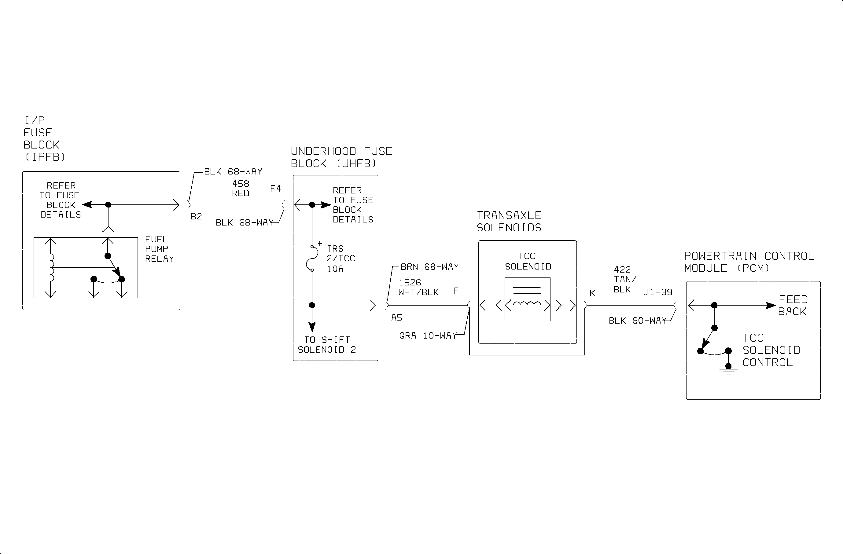
Circuit Description
The torque converter clutch (TCC) solenoid is used to apply and release TCC. The TCC can be applied in all forward gears. The powertrain control module (PCM) controls TCC by pulse width modulating an internal driver that pulls solenoid circuit to ground. When the TCC solenoid is commanded ON, circuit grounded, TCC is applied, which works opposite to all other four transaxle solenoids. The TCC solenoid circuit is monitored for low and high voltage faults. The PCM uses the crankshaft position sensor (CKP) and input speed sensor (ISS) to calculate RPM slip acros torque converter. The PCM will use this information to determine torque converter clutch (TCC) slip. DTC P0741 sets when the TCC solenoid is commanded ON and engine speed does not equal input shaft speed, indicating TCC slip.
DTC Parameters
DTC P0741 will set if speed difference across torque converter is greater than 280 RPM, indicating TCC stuck OFF when:
| • | The TCC has been commanded ON for longer than 5 seconds with no gear change. |
| • | The condition exists longer than 7.5 seconds |
| • | The condition exists twice in one ignition cycle |
| • | The engine speed is greater than 908 RPM. |
| • | The input speed is greater than 224 RPM. |
| • | The ECT is greater than 50°C (122°F). |
| • | The TFT is greater than 20°C (68°F). |
| • | DTCs P0336, P0716 or P0717 have not been set. |
DTC P0741 diagnostic runs continuously when the above conditions have been met.
DTC P0741 is a type A DTC
Diagnostic Aids
Important: If DTCs P0705, P0706, P0708, P0740, P0743, P0745, or P0789 is set, diagnose that DTC first. A diagnosed TCC solenoid circuit, shift solenoid circuit or low main line pressure DTC may have caused DTC P0741 to set.
Refer to "Test Section Diagnosis" for pressure apply points and for the following component/location description.
Make sure TCC solenoid is not intermittently sticking. Audible sound should be similar for all solenoids. A muffled tone indicates the need for replacement.
An intermittent open anywhere in the circuit or short to voltage on circuit 422 will cause no TCC. Use Scan tool to command TCC SOLENOID ON (PWM) by performing SOLENOID AUDIBLE CHECK. Wiggling wires while performing test may locate a problem.
The TCC will not apply if clutch priority valve is moving to make a shift due to 2nd, 3rd or 4th gear stuck On. DTC P0741 will be set.
The TCC solenoid resistance: 3.8-7.2 ohms
Nominal value: 4.5 ohms at 68°F
