Refrigerant Dye - Leak Testing
Whenever a refrigerant leak is suspected in the system or a service operation
is performed which results in disturbing lines or connections, it is advisable to
test for leaks.
Caution: R-134a service equipment or vehicle a/c systems should not be pressure tested
or leak tested with compressed air. Some mixtures of air/R-134a have been
shown to be combustible at elevated pressures. These mixtures are potentially dangerous
and may result in fire or explosion causing injury or property damage. Additional
health and safety information may be obtained from refrigerant and lubricant manufacturers.
Saturn vehicles are equipped with refrigerant dye in the air conditioning system.
This dye is installed in the receiver-dehydrator unit. The dye is distributed throughout
the system as the vehicle is run during validation at the factory.
The preferred procedure of diagnosing a leaking refrigerant system is as follows:
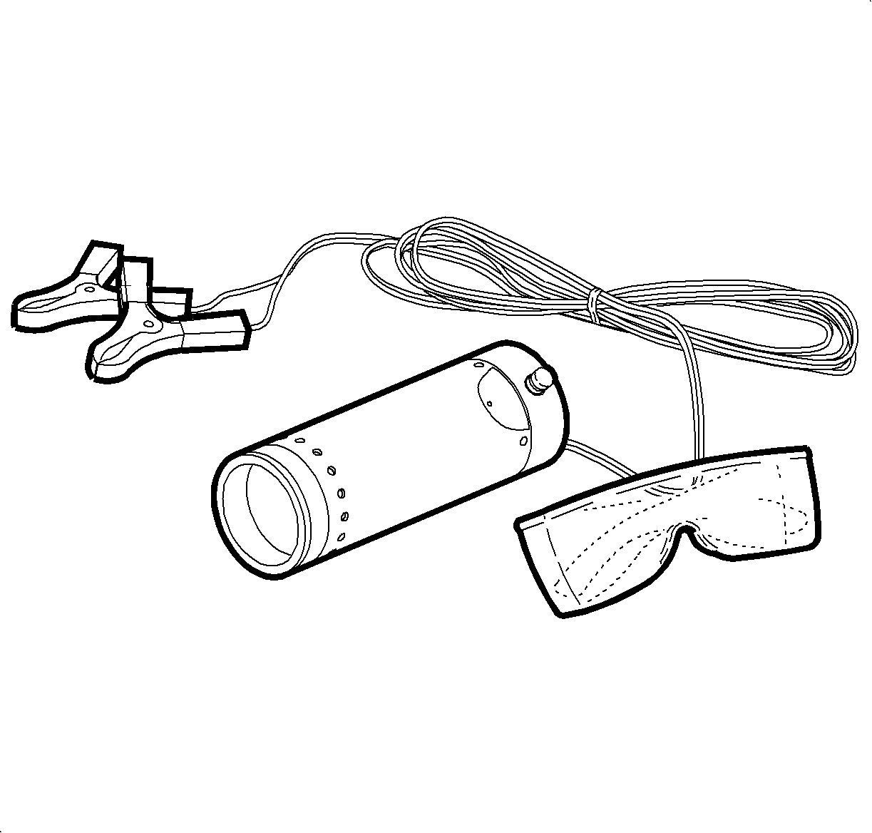
- Obtain service tool J 42220
with specially tinted goggles.
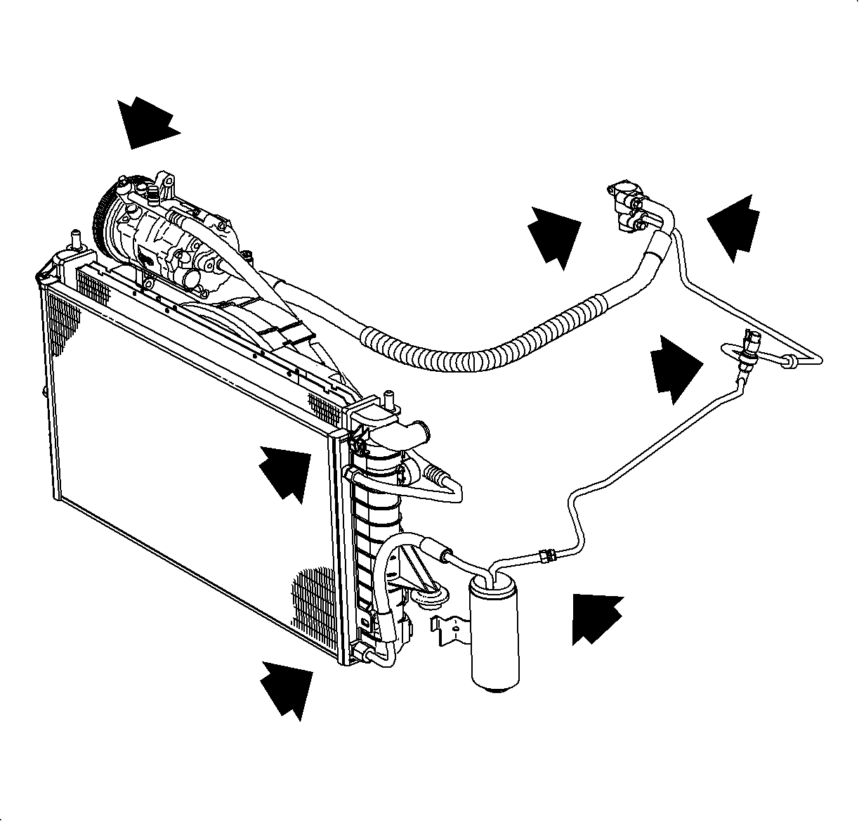
Important: A small amount of residue at various joints in the system may not be an actual
leak that needs repair.
- Point the black light at the refrigerant plumbing joints illustrated and inside
the blower motor housing as illustrated in the Electronic Leak Detector procedure.
- Observe any areas that have an excessive collection of glowing, yellow
to green, refrigerant/oil residue.
- Any area that shows excessive residue should be repaired. If the area
has some residue and you suspect it may be leaking, use of an electronic leak detector
is required.
- Follow the electronic leak testing of fittings and connections following.
- After the repair is done, check refrigerant charged A/C system with an
electronic leak detector to verify there are no more leaks.
- Clean any refrigerant dye on components with brake and choke cleaner,
Saturn P/N 21007432.
- If any refrigerant dye contacts an exterior paint surface, remove it by
performing the following steps:
| 8.1. | Carefully wash affected surfaces according to the Saturn Owner's Handbook
to remove any dirt and to ensure that paint is not scratched during dye removal. |
| 8.2. | Mix water and isopropyl alcohol to obtain 50/50 mixture. Soak a soft 100
percent cotton cloth towel with the solution and wet down affected areas to remove
dye. |
| 8.3. | After dye has been removed, wash affected areas and inspect to make sure
that the dye has been removed. |
Electronic Leak Testing
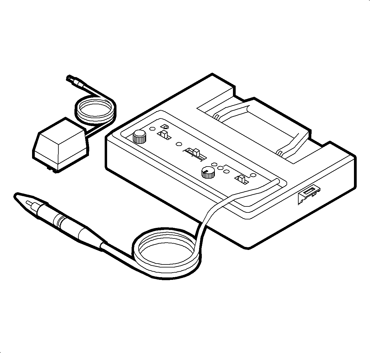
Caution: Care should be taken to prevent personal injury which could occur due to touching
a hot engine when testing. Tests should be done with the engine off and as cool as
possible. Do not operate the detector in a combustible atmosphere since its sensor
operates at a high temperature.
The successful use of this and any other electronic leak detector depends greatly
upon the scan rate and carefully following the manufacturer's instructions regarding
calibration, operation and maintenance. Each joint, including soldered, brazed and
welded areas, must be circled moving at 25-30 mm (1-2 in)
per second with the tip of the probe as close to the surface as possible. The tip
should be no more than 6.35 mm (1/4 in) away and must not block air
intake. A leak is indicated when the audible tone goes from a steady one to two
clicks per second to a solid alarm.
Liquid Leak Detector
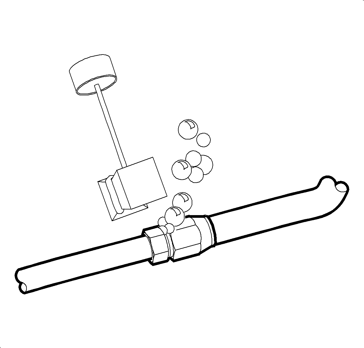
Important: Rinse soap solution from fitting before making repair.
There are a number of locations (such as fittings, valves, etc.) on the air
conditioning system where a liquid leak detector solution may be used to pinpoint
refrigerant leaks. Apply soap solution to the area in question. Bubbles will form
indicating a leak.
Electronic Leak Testing Of Fittings and Connections

- Install a R134a manifold gage set to determine if refrigerant is present in
the system. If no pressure is indicated, charge system with 0.50 kg (1 lb)
of refrigerant.
Low side service ports (1).
High side service ports (2).
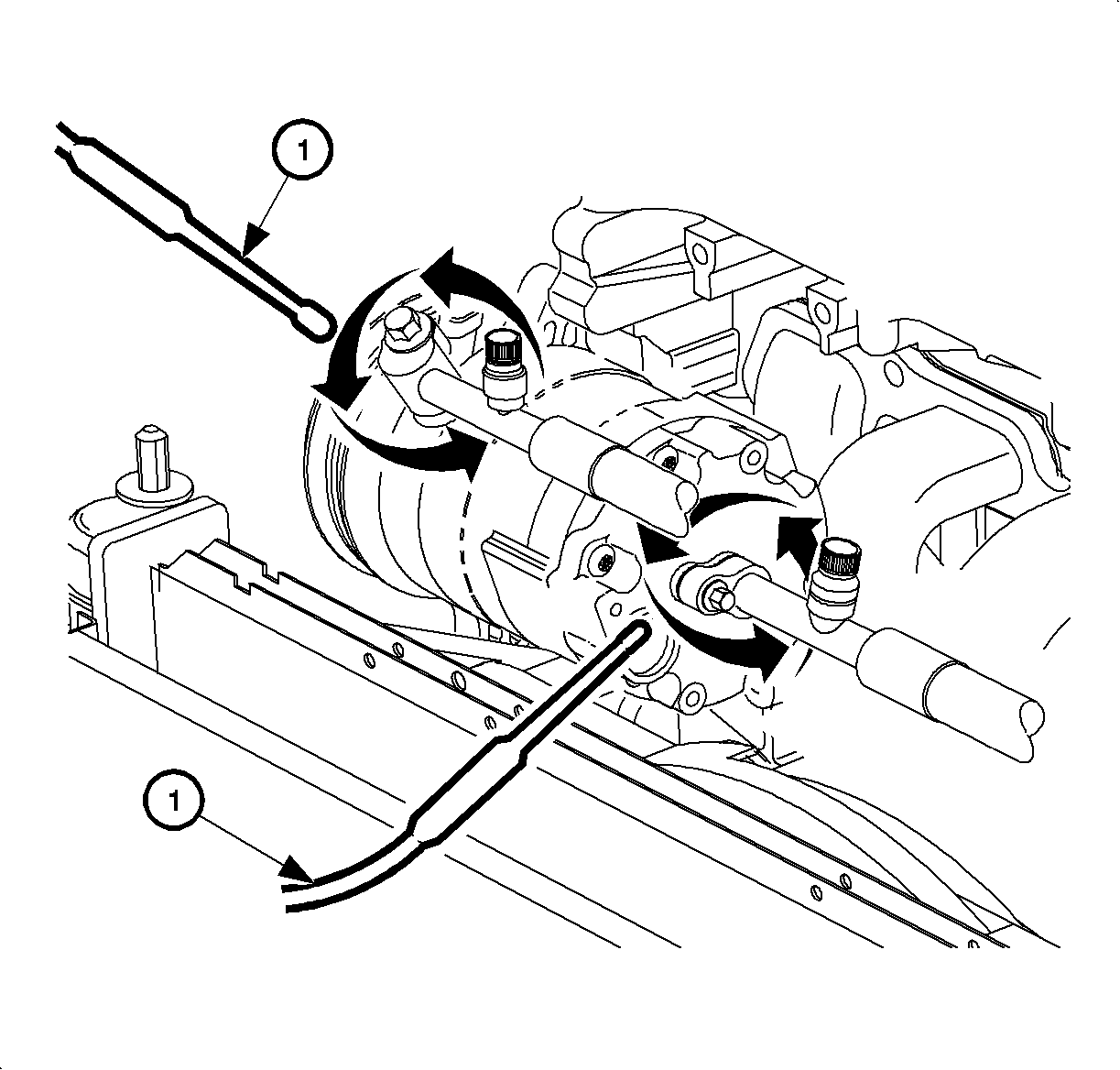
- Position the probe of the electronic leak detector to discharge the hose fittings:
| 2.1. | Move the probe (1) 25-50 mm (1-2 in)
per second around the connection to the compressor making sure air is able to flow
past the tip. |
| 2.2. | Move the probe to the service valve on the discharge hose. Circle the
service valve. |
| 2.3. | Check other possible sources of a refrigerant leak along the hose. |
- Position the probe of the electronic leak detector to the suction hose
fittings:
| 3.1. | Move the probe (1) 25-50 mm (1-2 in)
per second around the connection to the compressor making sure air is able to flow
past the tip. |
| 3.2. | Move the probe to the service valve on the suction hose. Circle the service
valve. |
| 3.3. | Check other possible sources of a refrigerant leak along the hose. |
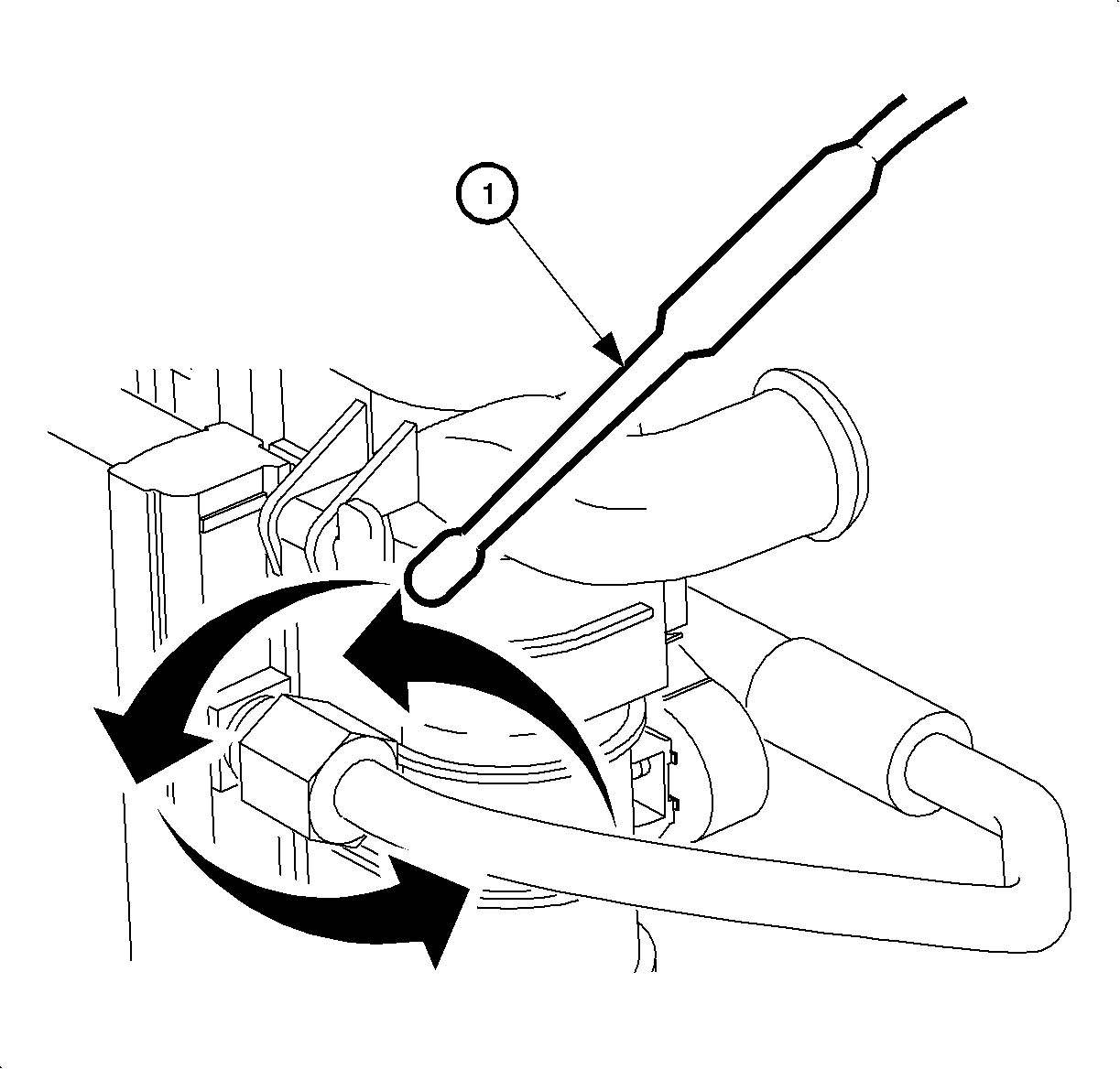
- Position the probe (1) of the electronic leak detector to the condenser
inlet fitting.
- Move the probe along the aluminum fins of the condenser and tubes within
the fins. Cover all soldered, brazed and welded areas.
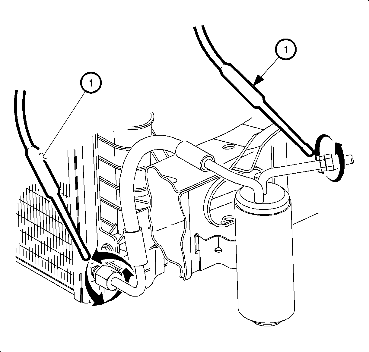
- Position the probe (1) of the electronic leak detector to the condenser
outlet fitting.
- Move the probe along the receiver-dehydrator hose assembly.
- Position the probe on top of the receiver-dehydrator.
- Position the probe to the receiver-dehydrator and liquid line connection.
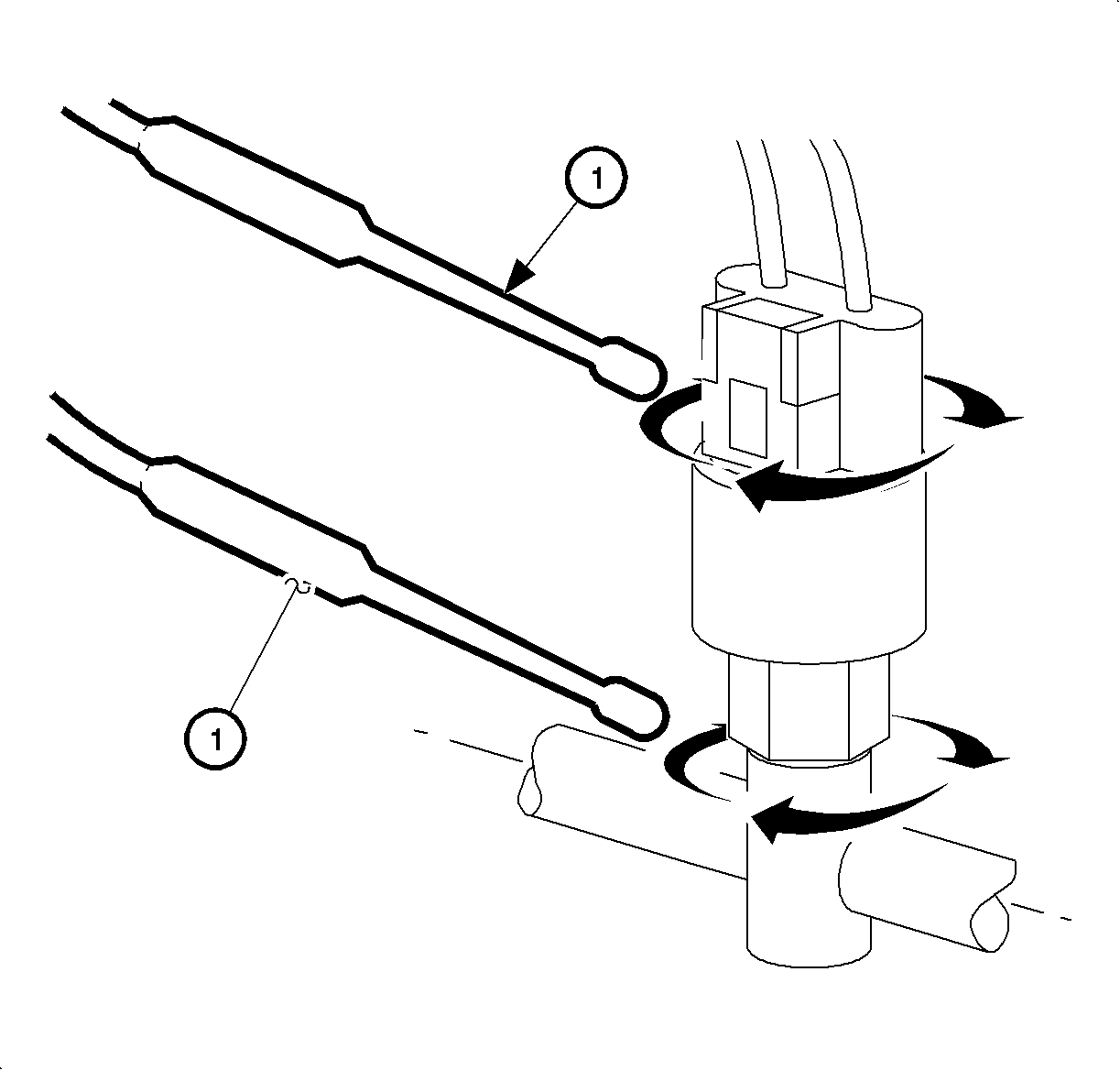
- Position the probe (1) to the pressure sensor.
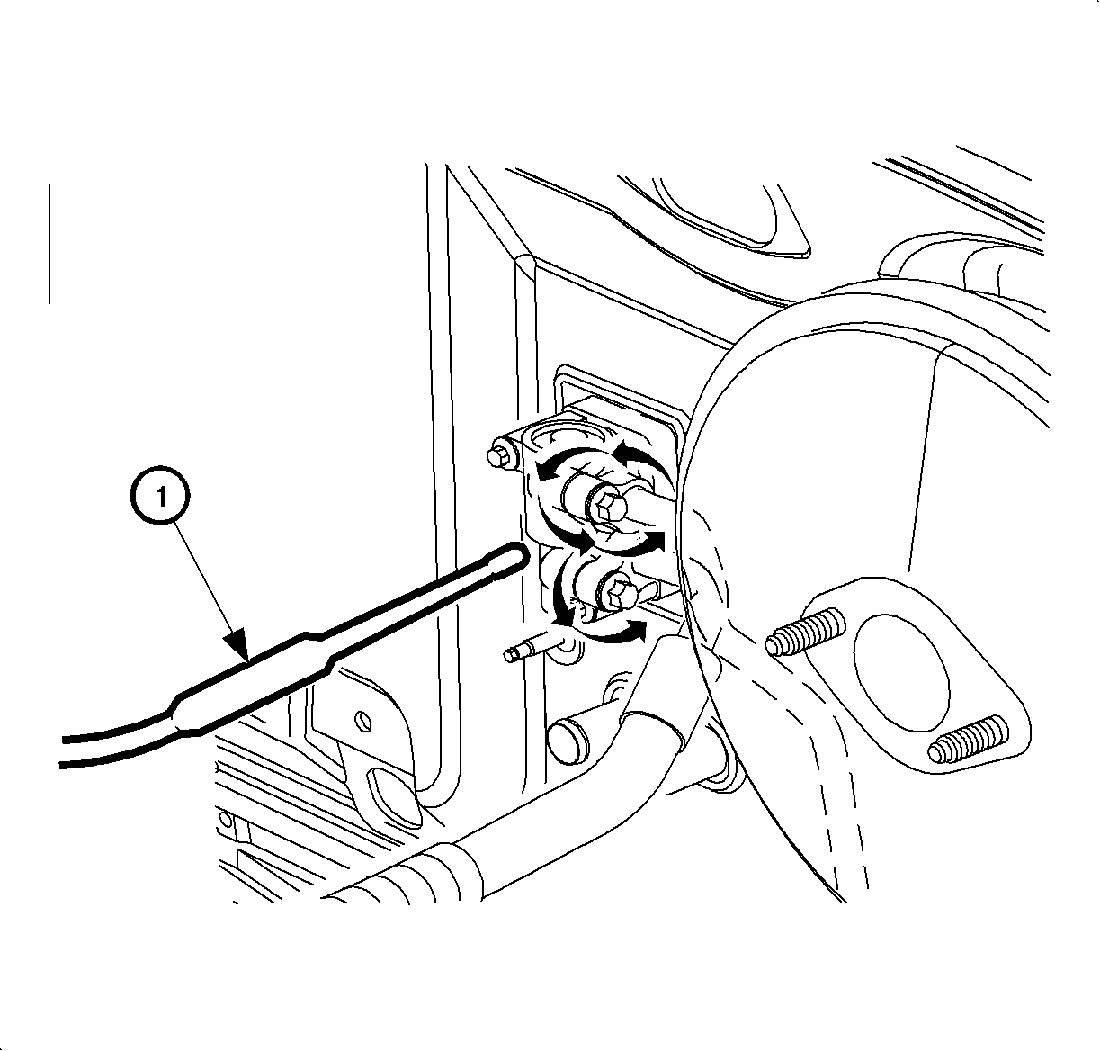
- Position the probe (1)
to the liquid line connection at the thermal expansion valve (TXV).
- Circle the entire area of the thermal expansion valve including the rear
portion that contacts cowl (engine side of front of dash).
Important: Turn On blower fan for at least 15 seconds before removing the blower motor
assembly. Wait 10 minutes before leak checking the evaporator. This step will reduce
the chance of misdiagnosis of the evaporator due to other possible contaminants
in the evaporator area that might trigger the electronic leak detector.
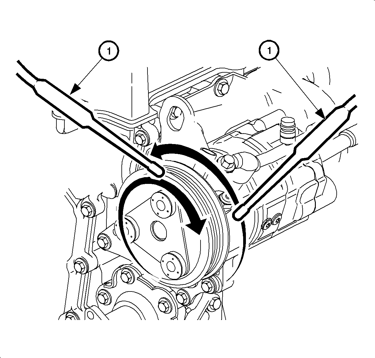
- Circle the compressor clutch area with the probe (1) in the front and back.
Important: Steps 14 and 15 pertain to left-hand drive vehicles only.
If the procedure is being performed on a right-hand drive vehicle, skip steps 14 and 15
and proceed with steps 16 and 17.
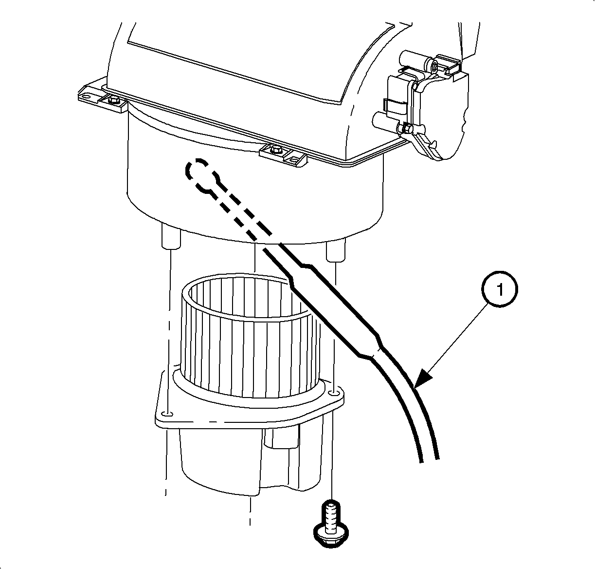
- Check evaporator leak:
| 14.1. | Disconnect the blower motor electrical connector. |
| 14.2. | Remove the blower motor mounting screws. |
| 14.3. | Remove the blower motor and cover. |
| 14.4. | Position the probe (1) inside of the blower motor housing. |
| 14.5. | Point the probe towards the left side of the vehicle or driver's position
(the evaporator is to the left of the blower motor housing). |
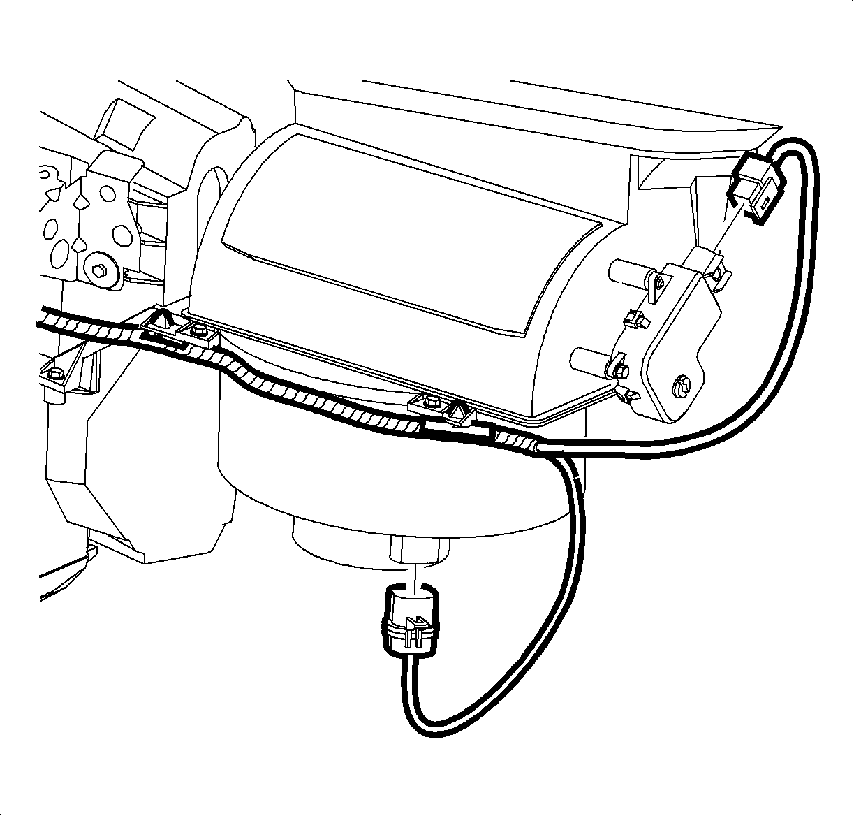
- After the evaporator leak check is complete, install the blower motor:
| 15.1. | Install the blower motor and cover. |
| 15.2. | Install the blower motor mounting screws. |
| 15.3. | Install the electrical connector to the blower motor. |
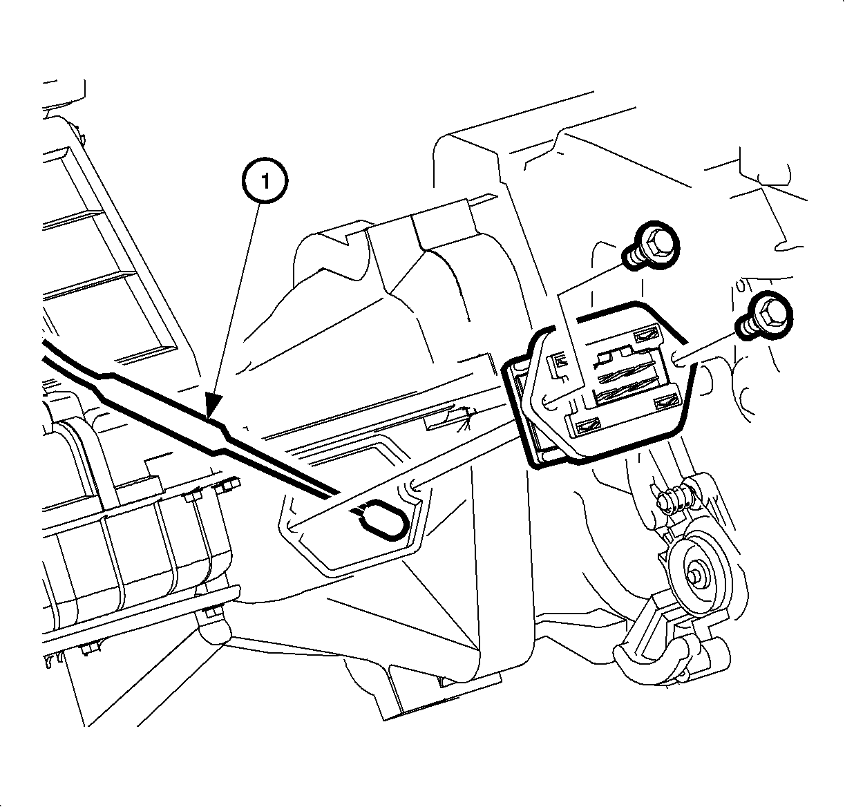
- Check evaporator leak (POSTAL VEHICLES ONLY):
| 16.1. | Disconnect the blower motor resistor electrical connector. |
| 16.2. | Remove the blower motor resistor mounting screws. |
| 16.3. | Remove the blower motor resistor. |
| 16.4. | Position the probe inside of the blower motor housing. |
| 16.5. | Point the probe towards the right side of the vehicle or driver's position
(the evaporator is to the right of the blower motor housing). |
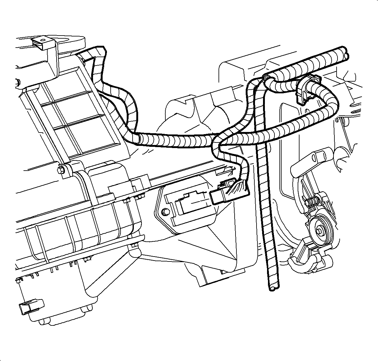
- After the evaporator leak check is complete, replace the blower motor resistor
(POSTAL VEHICLES ONLY):
| 17.1. | Install the blower motor resistor. |
| 17.2. | Install the blower motor resistor mounting screws. |
| 17.3. | Install the electrical connector to the blower motor resistor. |
- If the above procedures have not identified a refrigerant leak and you
still suspect there is one, recheck the above connections. Additionally, check the
path, along the entire routing of the A/C components, with an electronic detector,
for nicked or damaged hoses, fittings, bends in tubing and corrosion
under protective tubing. Check any hidden areas such as the receiver-dehydrator
routing.


