Removal Procedure
The transaxle range switch contains four switches that ground four different circuits. These circuits are 771 (switch A), 772 (switch B), 773 (switch C), and 776 (switch D). The switch also contains the backup lamp switch and the neutral/start switch.
The transaxle monitors these four circuits and determines what gear the operator has selected by the combinations of opens and grounds. Each combination indicates a specific selection in the manual shift quadrant (PRND32).
Refer to chart for transaxle range switch in this manual for further information.
- Remove air induction system.
- INSERT GRAPHIC SMPAT49040AA
- Disconnect shifter cable from control lever.
- Place control lever in the full clockwise position.
- Prevent the manual shift shaft from rotating by holding control lever while removing retaining nut from manual shift shaft. Remove control lever.
- Remove two switch-to-transaxle case bolts and remove switch.

Disconnect electrical connectors from selector switch.
Installation Procedure
- Install switch to transaxle and install switch to case bolts. Do not tighten bolts at this time.
- Install control lever-to-manual shift shaft.
- Prevent the manual shift shaft from rotating by holding control lever while installing retaining nut.
- Install cable to control lever and adjust cable. Refer to Shift Cable Adjustment in this manual.
- Before tightening transaxle range switch-to-case bolts, proceed to Adjustment procedure.
Notice: Refer to Fastener Notice in the Preface section.
Tighten
Tighten the nut to 12 N·m 106 lb in).
Adjustment
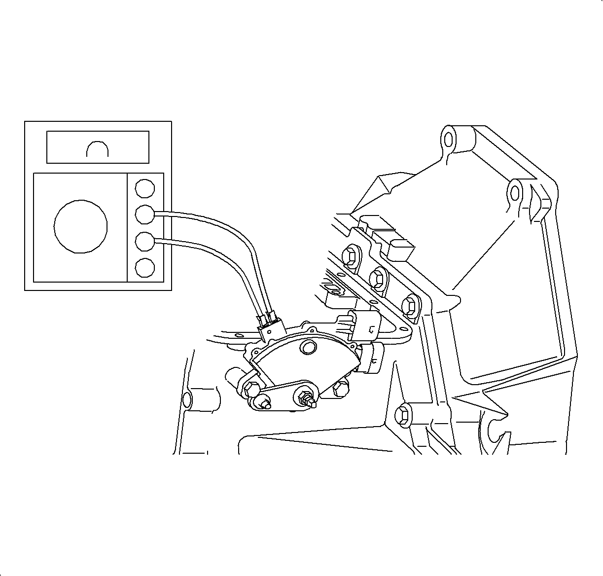
- Place transaxle in D (Drive). Use ohmmeter or continuity tester to check for continuity across terminals on selector switch. Rotate the transaxle range switch from the left fender towards the engine until continuity is achieved.
- Tighten switch to case bolts. After switch-to-case bolts have been tightened, check continuity.
- Connect electrical connectors.
- Install air induction system.

Important: While adjusting the transaxle range switch, always rotate the switch towards the engine to achieve continuity. A diagnostic trouble code DTC P0706 could result if this procedure is not followed.
Tighten
Tighten the bolt to 14 N·m (124 lb in).
Important: Digital Volt/ohm meter (DVM) with audible continuity test is preferred. Do not stick probe in transaxle range switch terminal hole, use male terminals on transaxle switch or faulty readings could occur.

Important: While adjusting the transaxle range switch, always rotate the switch towards the engine to achieve continuity. A DTC P0706 could result if this procedure is not followed.
Tighten
Tighten the air induction system fasteners to 10 N·m
(89 lb in)
