For 1990-2009 cars only
Circuit Description

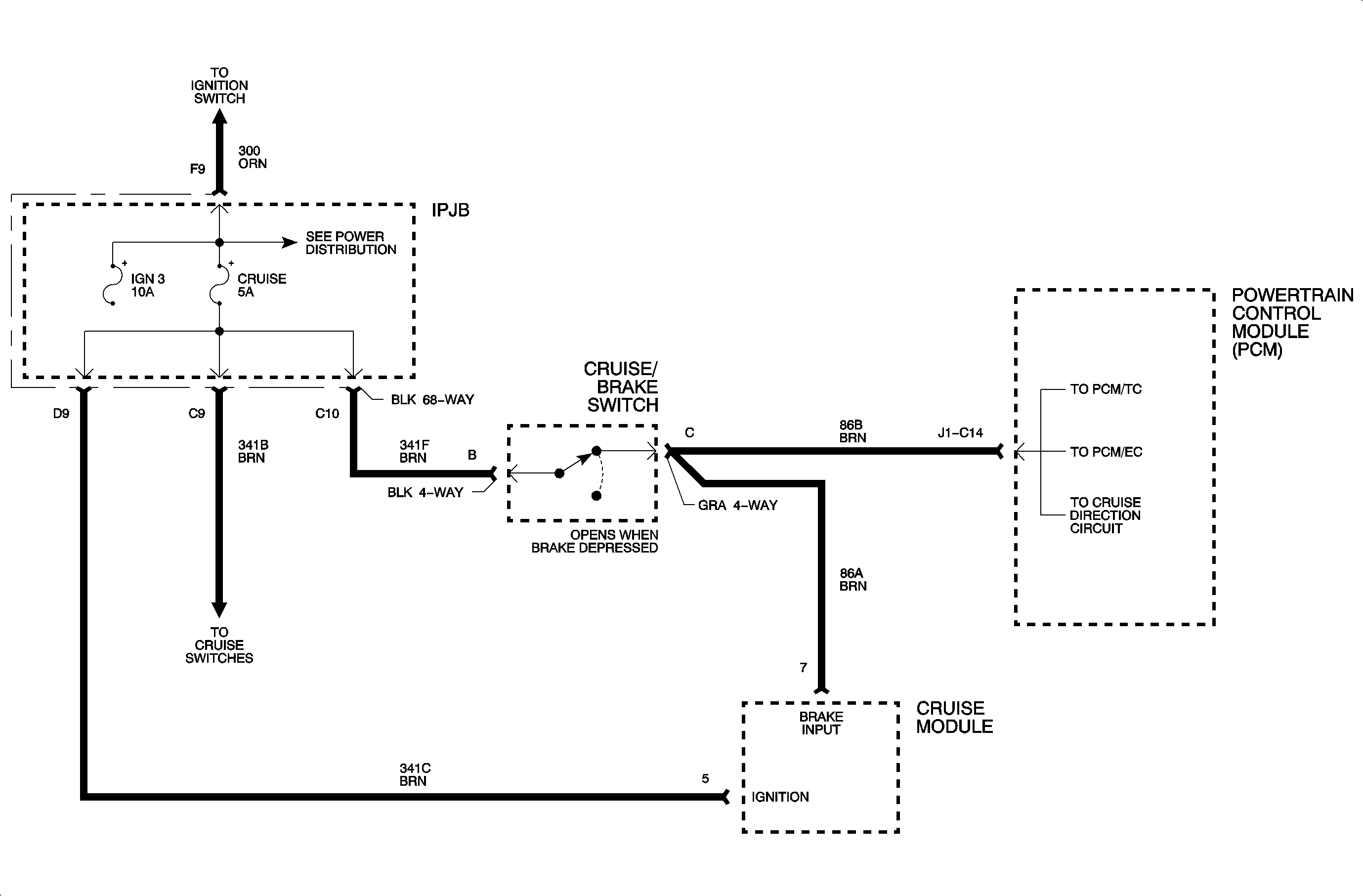
The brake switch is normally closed supplying 12 volts to the powertrain control module (PCM) at terminal J1C14 when the ignition is ON and the brake is OFF. A scan tool should display ON when the brake pedal is depressed and should read OFF with the brake pedal released.
Conditions for Setting the DTC
DTC P0572 will set if no voltage has been seen at circuit 86B when the vehicle has cycled 2 times from 0-60 km/h (0-37 mph).
Test Description
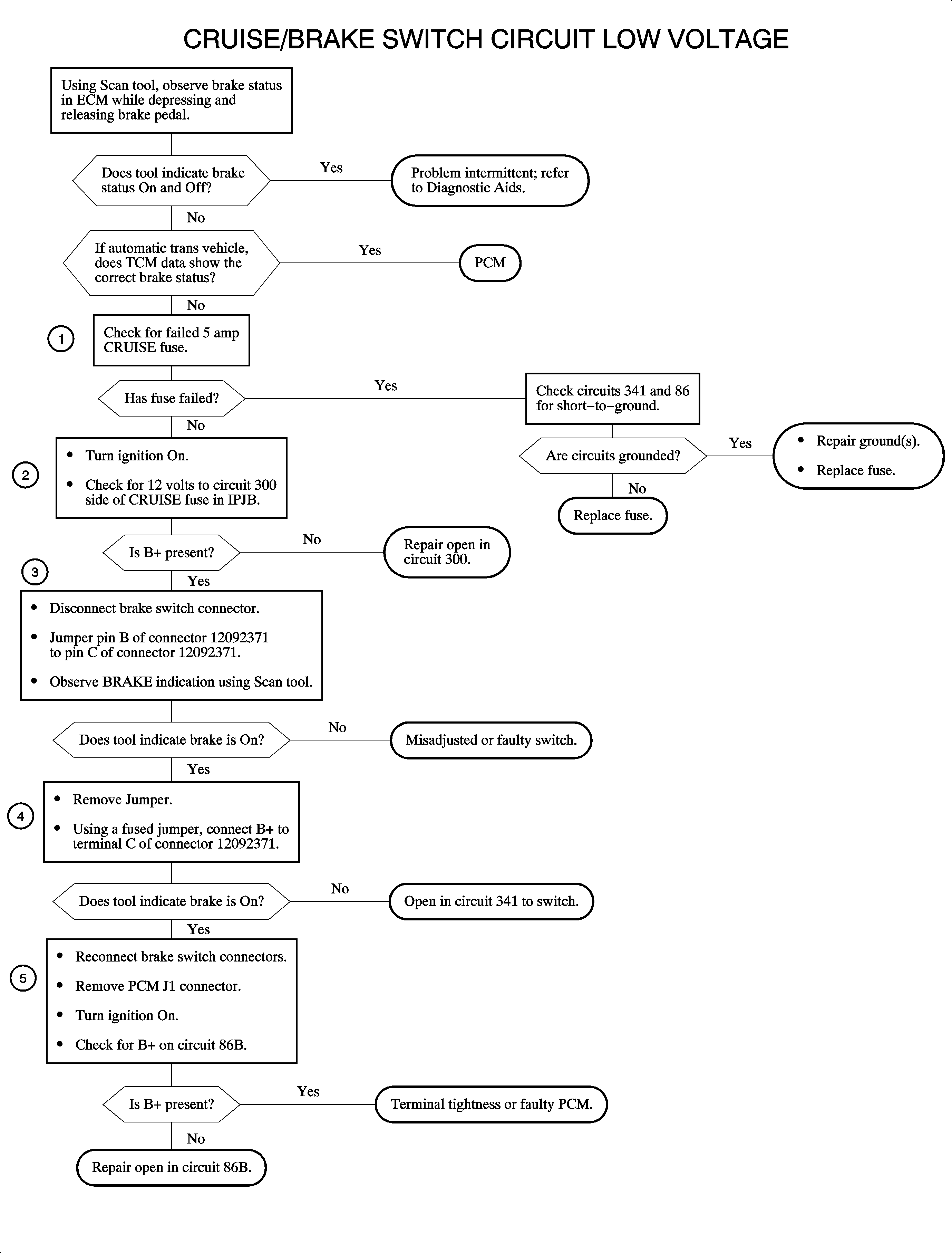
Numbered steps below refer to numbered steps on the chart.
- A ground in circuits 341F, 341B, or 341C will cause the (5A) CRUISE fuse to fail. If the fuse fails, DTC P0572 will be set and the cruise system will not operate if equipped. Also if cruise is present, DTC P1640 will be set if the fuse is faulty.
- If circuit 300 is open, DTC P0572 will be set. This test checks circuit 300 for opens.
- A switch that is out of adjustment or has failed, is open, this will cause DTC P0572 to be set. This step checks the wiring to and from the switch.
- An open in circuit 341F will cause DTC P0572 to set. This step checks circuit 341F for opens by verifying the PCM can read voltage on circuit 86B when voltage is applied.
- If circuit 86B is open, DTC P0572 will be set. This step indicates an open circuit 86B or a faulty PCM. With the brake pedal released, voltage should be present at the PCM pin J1C14.
Diagnostic Aids
The DTC could set by a customer who comes to a complete stop without using the foot brake.

