For 1990-2009 cars only
Instrument Cluster Replacement Left Hand Drive
Removal Procedure
- Disable the SIR System.
- Remove the screws from the DLC connector and steering filler panel.
- Remove hood release cable from lever.
- Remove steering column filler panel.
- Disconnect ignition switch electrical connector at right steering column bolt.
- Remove steering column bolts and lower column on front seat.
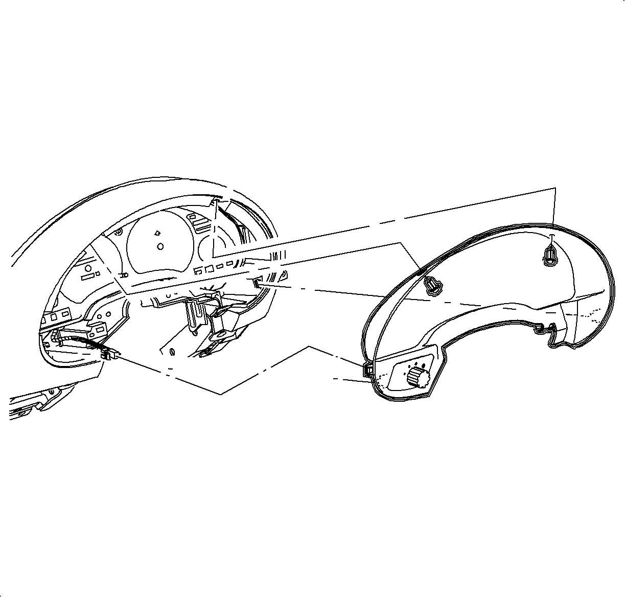
- Remove fasteners and pull instrument cluster trim bezel rearward at clip locations.
- Disconnect electrical connector from instrument panel dimmer switch.
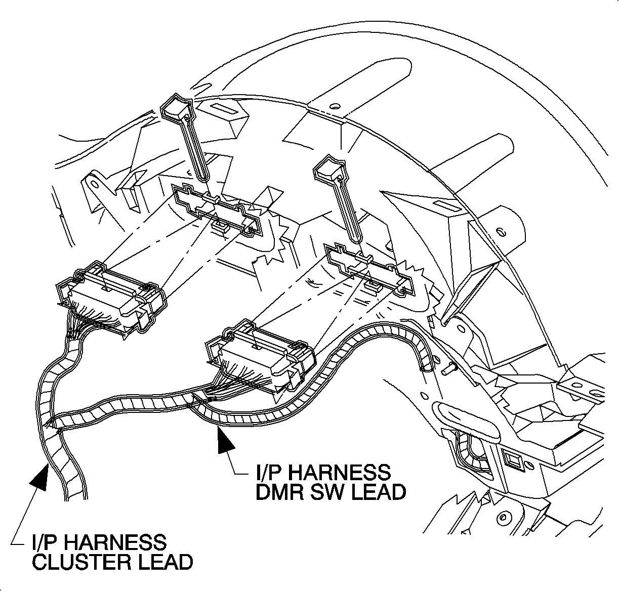
- Remove connector position assurance (CPA) devices and disconnect electrical connectors from instrument panel cluster assembly by squeezing tabs on each side of connector.
- Remove front and rear instrument panel cluster assembly screws.
- Remove instrument panel cluster assembly.


Installation Procedure
- Install instrument panel cluster assembly.
- Install and tighten instrument panel cluster assembly screws.
- Connect electrical connectors to I/P cluster assembly.
- Install CPA devices.
- Connect electrical connector to I/P dimmer switch.
- Install instrument cluster trim bezel. Push in at clip locations.
- Install push pin fasteners.
- Raise steering column into position.
- Install and torque bolts.
- Connect ignition switch electrical connector at right steering column bolt.
- Install hood release cable to lever.
- Install steering column filler panel and DLC connector.
- Install and tighten screws.
- Enable the SIR System.


Tighten
Tighten bolts to 35 N·m (26 lb ft)


Instrument Cluster Replacement Right Hand Drive Domestic
Removal Procedure
- Disable the SIR System. Refer to Disabling the SIR System.
- Remove the screws from the data link connector (DLC) and the steering column filler panel.
- Lower the steering column filler panel and remove the hood release handle assembly.
- Disconnect the ignition switch electrical connector at the right steering column bolt.
- Remove the steering column bolts and the lower column onto the front seat.
- Remove the fasteners and pull the instrument cluster trim bezel rearward at the clip locations.
- Disconnect the electrical connector from the instrument panel dimmer switch and the defroster switch.
- Remove the connector position assurance (CPA) devices and disconnect the electrical connectors from the instrument cluster by squeezing the tabs on each side of the connector.
- Remove the front and the rear instrument cluster screws.
- Remove the instrument cluster.


Installation Procedure
- Install the instrument cluster.
- Install the front and the rear screws.
- Connect the electrical connectors to the instrument cluster.
- Install the CPA.
- Connect the electrical connector to the dimmer switch and defroster switch.
- Install the instrument cluster trim bezel. Push in at the clip locations.
- Install the push pin fasteners.
- Raise the steering column into position.
- Install and torque the bolts
- Connect the ignition switch electrical connector at the right steering column bolt.
- Install the hood release handle assembly to the steering column filler panel.
- Install the steering column filler panel and the DLC.
- Install and torque the screws.
- Enable the SIR System. Refer to Enabling the SIR System.

Notice: Refer to Fastener Notice in the Preface section.
Tighten
Tighten the rear screws to 3 N·m (26 lb in).


Tighten
Tighten the bolts to 35 N·m (26 lb ft).

Tighten
Tighten the handle to 1.5 N·m (13 lb in).

Tighten
Tighten the screws to 2.2 N·m (20 lb in).
