Service Manual Update for 1996 Revised Powertrain Controls Service Manual

| Subject: | Service Manual Update for 1996 Revised Powertrain Controls Service Manual |
| Models: | 1996 Saturns |
Purpose
Due to a printing error, two pages pertaining to diagnostic trouble code (DTC) P1406 were omitted from the "1996 Revised Powertrain Controls Service Manual." Refer to this bulletin when diagnosing DTC P1406, complete diagnostics are on the following four pages.
DTC P1406 EGR - PINTLE POSITION ERROR
EGR - PINTLE POSITION ERROR (CHART 1 OF 2)
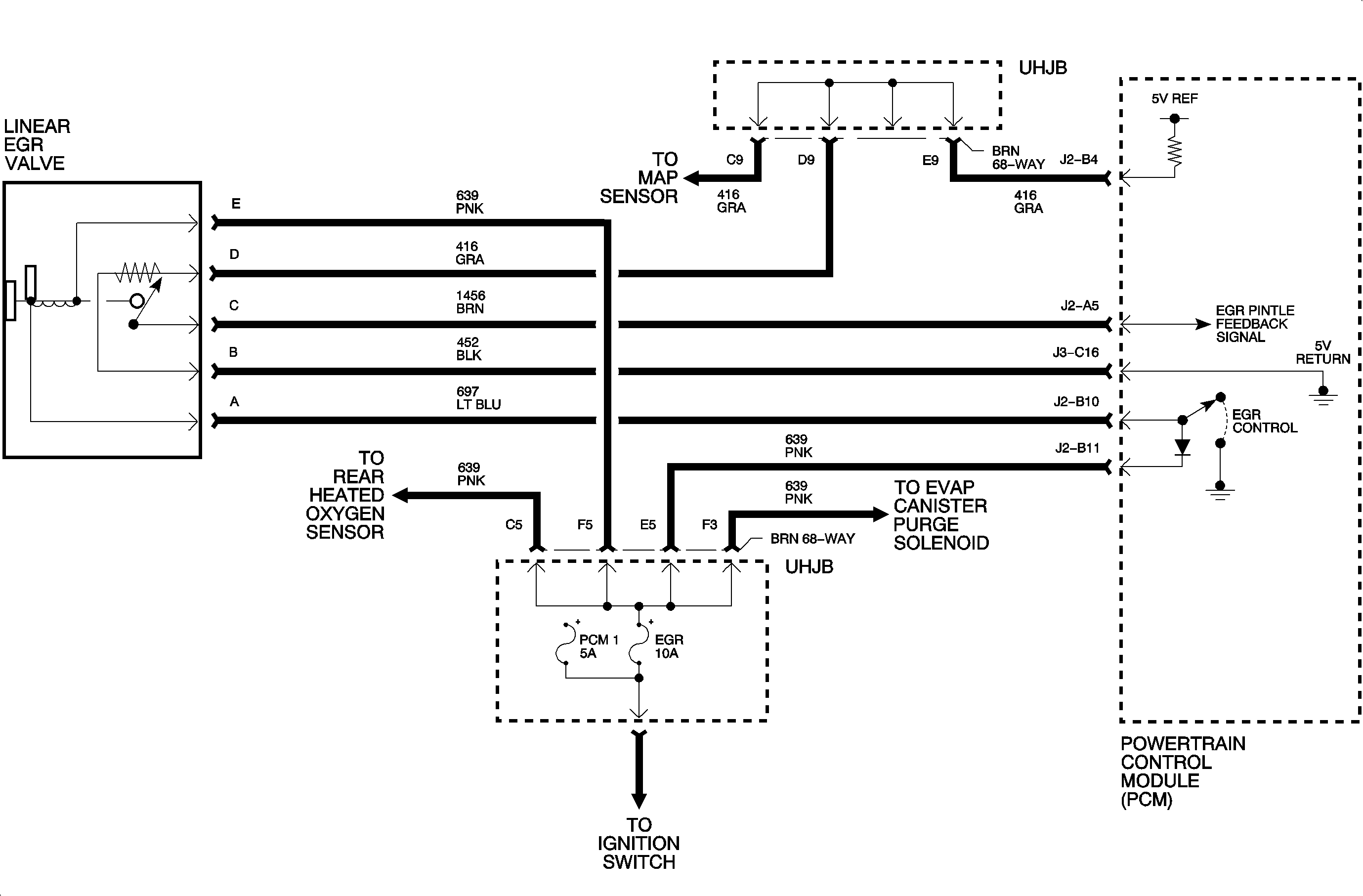
The linear EGR system consists of a linear EGR valve, the PCM and its associated wiring. The EGR valve solenoid is controlled directly by the PCM when certain conditions have been met. The PCM contains a diode feedback circuit which dissipates energy when the valve is cycled Off. When the PCM grounds the valve, a diagnostic feedback signal can determine if the valve had actually moved. DTC P1406 has been defined to monitor the feedback signal. This diagnostic will determine if the position feedback signal properly falls within the correct range under different valve operating conditions.
DTC PARAMETERS
- An open or short circuit (voltage less than 0.20 volts or greater than 4.8) - open/short test:
- Valve is being commanded closed and the feedback voltage is too high (closed valve test);
- If the actual position feedback signal does not match the desired position being commanded (pintle position error test). (Actual feedback voltage must be within 0.50 volts [10%] of the desired position.)
or
or
When any one of these tests have failed, a DTC will set and EGR will be disabled for that ignition cycle. The malfunction history record will indicate which one of these tests has failed to aid in diagnostics.
Important: The EGR position error is continuously checked when EGR is commanded On. All three tests must have been run for a DTC P1406 to pass.
Important: The EGR valve may operate at any engine coolant temperature regardless of loop mode.
TEST DESCRIPTION
- Normal closed valve position feedback voltage should be between 0.25-1.5 volts. This value may change with temperature.
- A voltage of less than 0.2 volts indicates a problem with the position feedback circuit. A voltage of greater than 1.5 volts could be caused by a position feedback circuit problem, a valve stuck open or a solenoid being energized.
DIAGNOSTIC AIDS
When attempting to diagnose an intermittent problem use the Scan tool to review malfunction history diagnostic information. The supplemental data can be used to duplicate a problem.
Check the tightness of the female terminal grip with a spare male terminal.
| • | B + voltage is supplied to the E terminal on the EGR valve when ignition is On. |
| • | Check EGR10 amp fuse in the UHJB before diagnostic this DTC. |
| • | Carbon buildup around the pintle valve may restrict pintle movement. |
| • | An open in the diode feedback circuit will result in unstable valve operation resulting in vehicle surge. |
| graphic |
DTC P1406 EGR - PINTLE POSITION ERROR
EGR - PINTLE POSITION ERROR (CHART 2 OF 2)
The linear EGR system consists of a linear EGR valve, the PCM and its associated wiring. The EGR valve solenoid is controlled directly by the PCM when certain conditions have been met. The PCM contains a diode feedback circuit which dissipates energy when the valve is cycled Off. When the PCM grounds the valve, a diagnostic feedback signal can determine if the valve had actually moved. DTC P1406 has been defined to monitor the feedback signal. This diagnostic will determine if the position feedback signal properly falls within the correct range under different valve operating conditions.
DTC PARAMETERS
- An open or short circuit (voltage less than 0.20 volts or greater than 4.8) - open/short test:
- Valve is being commanded closed and the feedback voltage is too high (closed valve test);
- If the actual position feedback signal does not match the desired position being commanded (pintle position error test). (Actual feedback voltage must be within 0.50 volts [10%] of the desired position.)
or
or
When any one of these tests have failed, a DTC will set and EGR will be disabled for that ignition cycle. The malfunction history record will indicate which one of these tests has failed to aid in diagnostics.
Important: The EGR position error is continuously checked when EGR is commanded On. All three tests must have been run for a DTC P1406 to pass.
Important: The EGR valve may operate at any engine coolant temperature regardless of loop mode.
TEST DESCRIPTION
1. The actual pintle position voltage should increase as the valve is opened. If feedback voltage is erratic and the valve is cycling open then closed, check circuit 639 (from PCM pin J2B11 and UHJB pin E5.) An open circuit 639 will cause the valve to become unstable and will set a position error on DTC 1406.
DIAGNOSTIC AIDS
When attempting to diagnose an intermittent problem use the Scan tool to review malfunction history diagnostic information. The supplement data can be used to duplicate a problem.
Check the tightness of the female terminal grip with a spare male terminal.
| • | B + voltage is supplied to the E terminal on the EGR valve when the ignition is On. |
| • | Check EGR10 amp fuse in the UHJB before diagnosing this DTC. |
| • | Carbon buildup around the pintle valve may restrict pintle movement. |
| flowchart |
