Service Information on 1996 Model Year Vehicles with Misfire Calibration Installed

| Subject: | Service Information on 1996 Model Year Vehicles with Misfire Calibration Installed |
| Models: | 1996 Saturns with misfire calibration installed |
Purpose
The misfire calibration for 1996 model year vehicles includes diagnostic enhancements that were not included in the 1996 model year production calibration. As a result, some diagnostic trouble codes (DTCs) will be added once the misfire calibration is downloaded in 1996 model year vehicles.
The following DTCs are added for the 1996 misfire calibration and will only set if the misfire calibration is installed:
DTC | Fault Description |
|---|---|
P0404 | EGR Pintle Position Error |
P0405 | EGR Voltage Out of Range |
P0711 | Trans Fluid Temp Sensor Range/Performance |
P1404 | EGR Closed Position Error |
P0105 | MAP/TP Rationality Check |
P1336 | Crankshaft Adaptive not Learned |
The current 1996 Powertrain Controls Service Manual does not contain diagnostic procedures for the added DTCs. Refer to the attached diagnostic procedures when diagnosing the additional DTCs for 1996 model year vehicles with the misfire calibration installed.
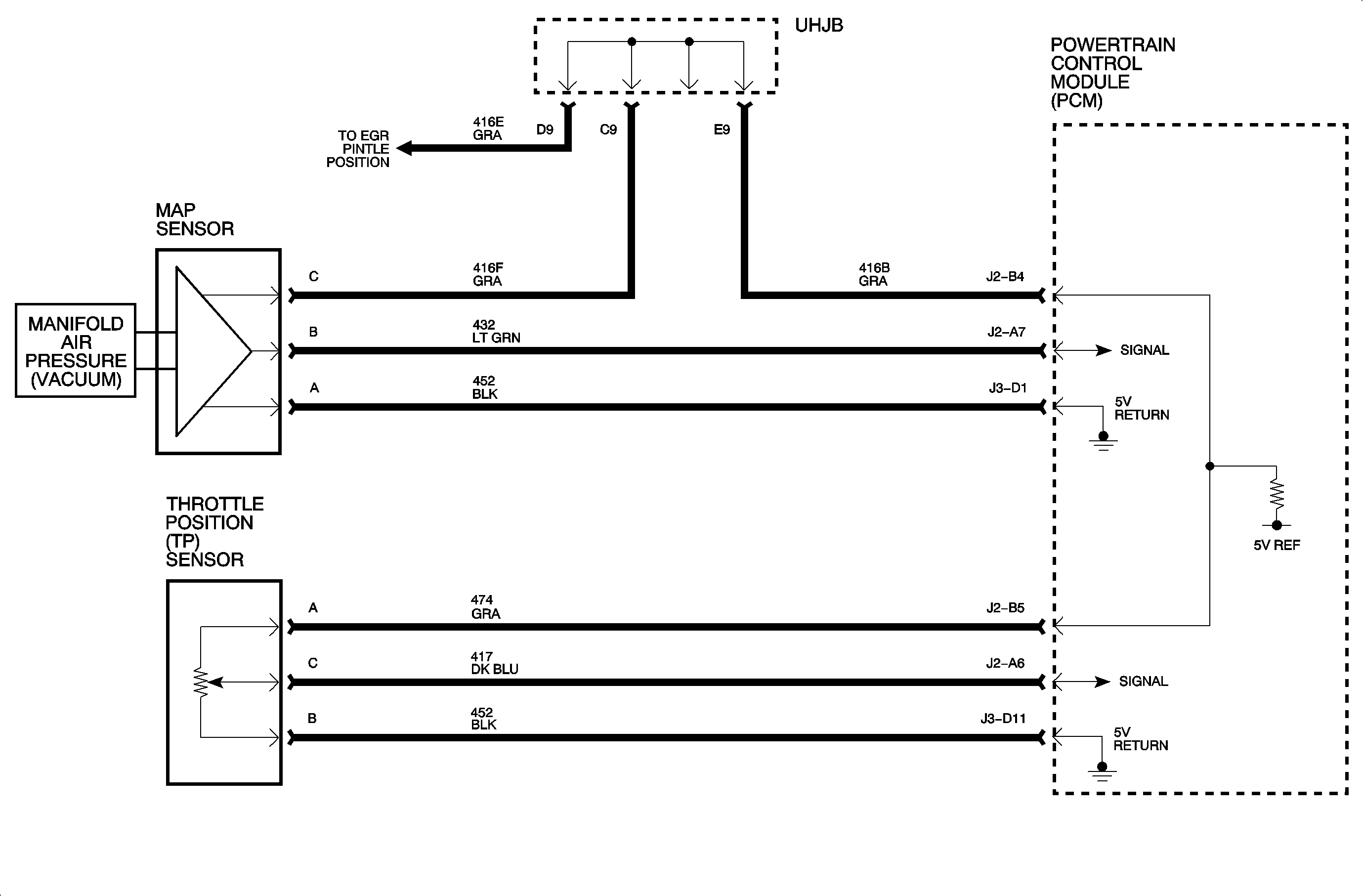
DTC P0105 - MAP/TP SENSOR CIRCUIT - RANGE/PERFORMANCE

MAP/TP SENSOR CIRCUIT - RANGE/PERFORMANCE
The PCM has internal tables that compare MAP sensor values with TP sensor values. The MAP sensor is a variable resistor that responds to changes in intake manifold pressure. The voltage ranges from 1-1.5 volts at idle (high manifold vacuum) to 4-4.5 volts at wide open throttle (low manifold vacuum). The TP sensor is a potentiometer which responds to changes in throttle plate angle. At a closed throttle position, output of the sensor is low (approximately 0.5 volts). As the throttle plate opens, the output signal increases so that at wide open throttle, the output will be high (approximately 5 volts).
DTC PARAMETERS
DTC P0105 will set if MAP or TP value is out of range greater than 2 seconds when:
| • | No P0107, P0108, P0122, P0123, P0506, or P0507 DTCs are present. |
| • | RPM between 1600 and 4000. |
| • | RPM change is less than 100. |
| • | Steady EGR command. |
| • | A/C command is unchanged. |
| • | IAC change is less than 10 counts. |
DIAGNOSTIC AIDS
This DTC will set if either MAP or TP is out of range. To distinguish which one failed, review malfunction history information and attempt to duplicate the conditions.
Check sensor and PCM connector for corrosion.
With the engine Off and key On, the map reading should be the same as the barometric reading because manifold pressure is equal to atmospheric pressure (no vacuum - high voltage). Comparing this reading to a known good vehicle with the same sensor is a good way to check accuracy of a suspect sensor. Readings should be within 0.4 volts.
DTC P0404 EGR - PINTLE POSITION ERROR

EGR - PINTLE POSITION ERROR
The linear EGR system consists of a linear EGR valve, the PCM and its associated wiring. The EGR valve solenoid is controlled directly by the PCM when certain conditions have been met. The PCM contains a diode feedback circuit which dissipates energy when the valve is cycled Off. When the PCM grounds the valve, the diagnostic feedback signal can determine if the valve had actually moved. DTC P0404 has been defined to monitor the feedback signal. This diagnostic will determine if the position feedback signal properly falls within the correct range under different valve operating conditions.
DTC PARAMETERS
| • | If commanded position is greater than 80%, actual position must be within 26 counts (10% [0.5 volts]) of commanded. |
| • | If commanded position is less than 80%, actual position must be within 60 counts (24% [1.1 volts]) of commanded. |
| • | Two consecutive ignition cycles while the diagnostic runs with an active fault. |
When either one of these tests have failed, a DTC will set and EGR will be disabled for that ignition cycle. The malfunction history will indicate which one of these tests has failed to aid in diagnostics.
Important: The EGR position error is continuously checked when the EGR is commanded On.
Important: The EGR valve may operate at any engine coolant temperature regardless of loop mode.
Important: When this DTC sets, some EGR functions will be disabled for the duration of that ignition cycle. When repairs are complete, codes must be cleared and ignition keyed off for at least 10 seconds to allow proper operation.
DIAGNOSTIC AIDS
| • | Check for backed out or damaged terminals. |
| • | Check the tightness of the female terminal grip with a spare male terminal. |
| • | Check for B+ voltage at the E terminal on the EGR valve when the ignition is On. |
| • | Check EGR 10-amp fuse in the UHJB before diagnosing this DTC. |
| • | Carbon buildup around the pintle valve may restrict pintle movement. |
| • | An open in the PCM diode feedback circuit will result in unstable valve operation resulting in vehicle surge. |
| • | Due to moisture associated with the exhaust system, the EGR valve may freeze and stick in extreme cold ambient conditions. |

DTC P0405 EGR - VOLTAGE OUT OF RANGE - FEEDBACK VOLTAGE LOW

EGR - VOLTAGE OUT OF RANGE - OPEN/SHORT
The linear EGR system consists of a linear EGR valve, the PCM and its associated wiring. The EGR valve solenoid is controlled directly by the PCM when certain conditions have been met. The PCM contains a diode feedback circuit which dissipates energy when the valve is cycled Off. When the PCM grounds the valve, a diagnostic feedback signal can determine if the valve had actually moved. DTC P0405 has been defined to monitor the feedback signal. This diagnostic will determine if the position feedback signal properly falls within the correct range under different valve operating conditions.
DTC PARAMETERS
DTC P0405 will set if the following conditions are met:
| • | IGN voltage is above 11.0 volts. |
| • | Voltage is less than 0.20 volts. |
| • | Condition present for greater than five seconds. |
When this DTC fails, EGR will be disabled for the entire ignition cycle. The malfunction history record will aid in diagnosis.
Important: The EGR valve may operate at any engine coolant temperature regardless of loop mode.
TEST DESCRIPTION
- Normal closed valve position feedback voltage should be greater than 0.20 volts at all times.
- A voltage of less than 0.2 volts indicates a problem with the position feedback circuit.
DIAGNOSTIC AIDS
| • | Check for backed out or damaged electrical terminals. |
| • | Check the tightness of the female terminal grip with a spare male terminal. |
| • | A short to ground in the 5-volt reference will set both a P1635 and a P0405. If both are set, diagnose P1635 first. |
| • | An open in the 5-volt reference will set only the P0405. |
| • | An open in the PCM diode feedback circuit will result in unstable valve operation resulting in vehicle surge. |

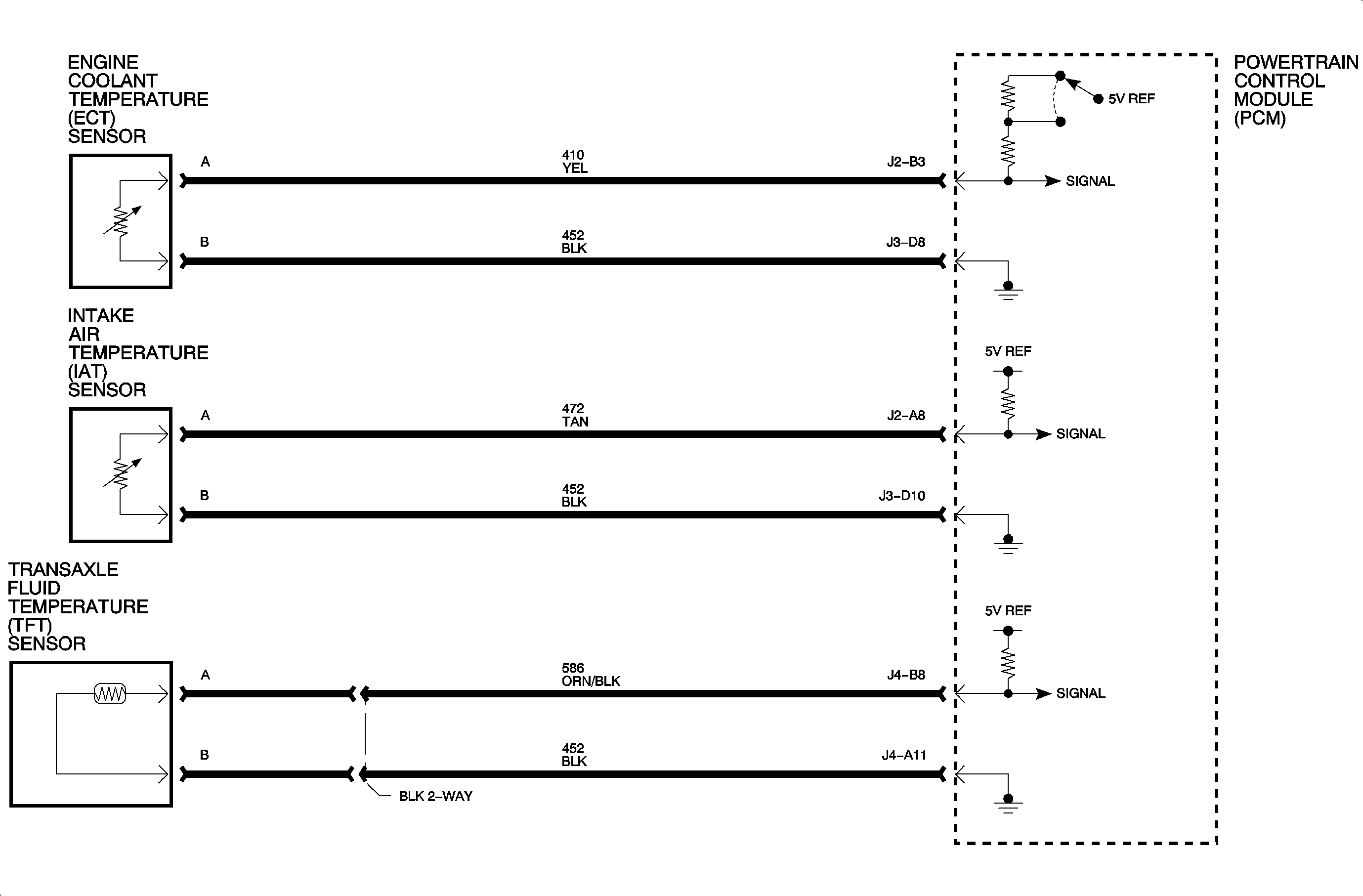
DTC P0710 AND P0711- TRANSAXLE FLUID TEMPERATURE IAT/ECT SENSOR - RANGE/PERFORMANCE - SKEWED SENSOR

TRANSAXLE FLUID TEMPERATURE/IAT/ECT SENSOR - RANGE/PERFORMANCE - SKEWED SENSOR
The transaxle fluid temperature sensor, engine coolant temperature sensor (ECT) and the intake air temperature sensor (IAT) are thermistor circuits. When the sensors are cold, they have high resistance and high sensor voltage. As the temperature increases, this resistance and voltage decreases. The PCM supplies a five-volt signal to the sensors, which is also connected to ground. The PCM reads the voltage drop on the sensor signal lines to determine the corresponding temperature.
DTC PARAMETERS
DTC P0710 is set when the PCM has detected the following conditions for more than 25.6 minutes:
| • | No ground/open in the temperature circuit. |
| • | No short in the temperature circuit. |
| • | Temperature value (TV) is less than a calculated temperature based on engine temperature (ET) and intake air temperature (IAT). |
DTC P0711 is set when the PCM/TC has completed two warm-up cycles with the following parameters detected:
| • | Engine coolant below 30°C (80°F) after exceeding 71°C (160°F). |
| • | IAT and ECT within 6°C (10°F). |
| • | Transaxle fluid temperature reading is greater than 9°C (16°F) of the IAT during start-up. |
Important: The transaxle fluid temperature ECT and IAT sensors are continuously checked when ignition is On.
Notice: Visually inspect the transaxle fluid temperature, ECT and IAT wires for evidence of shorts to battery/ignition voltage. Shorts to battery/ignition voltage will skew the sensor's resistance and cause DTC P0710 and P0711 to set.
DIAGNOSTIC AIDS
DTC P0711 may set if the vehicle is towed with the front wheels on the ground. If it is suspected that the vehicle has been towed recently, clear the DTC and return vehicle to the customer.
Important: DTC Code P0711 can not be cleared until the TFT sensor passes at least one warm-up cycle. Refer to P0711 DTC Parameters for specific requirements.
With ignition On and engine Off, observe the transaxle fluid temperature vs ECT vs IAT sensor after the vehicle obtained a cold soak.
Refer to Description and Operation on following page for transaxle fluid temperature, ECT and IAT sensors Temperature vs Resistance chart.
Important: The PCM uses two internal circuits to identify transaxle temperature. One circuit is used for temperatures of 48°C (118°F) and below. If either circuit has failed, the DTC will set. However, the temperature may look normal in the other range.
Test low scale with engine at room temperature and high scale with engine at normal operating temperature (above 70°C [158°F]).
The following chart lists the following chart lists the possible thermal sensor faults and associated DTC.
DTC Fault | IAT | ECT | Transaxle Fluid Temperature Sensor |
|---|---|---|---|
P0710 | Skewed high | Normal | Normal |
P0710 | Normal | Skewed High | Normal |
P0710 | Normal | Normal | Skewed High |
P0711 | Skewed Low | Normal | Normal |
P0711 | Normal | Skewed Low | Normal |
P0711 | Normal | Normal | Skewed Low |
The following chart lists the resistances of the transaxle fluid temperature, IAC and ECT sensors compared to temperature.
DEGREES (°C) | DEGREES (°F) | SENSOR RESISTANCE (OHMS) |
|---|---|---|
-40 | -40 | 77k - 109k |
-29 | -20 | 39k- 53k |
-18 | 0 | 21k - 27k |
-7 | 20 | 11k - 15k |
4 | 40 | 6.6k - 8.4k |
16 | 60 | 3.9k - 4.5k |
27 | 80 | 2.4k - 2.7k |
38 | 100 | 1.5k - 1.7k |
49 | 120 | .98k - 1.1k |
60 | 140 | 650 - 730 |
72 | 160 | 430 - 480 |
83 | 180 | 302 - 334 |
94 | 200 | 215 - 235 |
105 | 220 | 159 - 172 |
120 | 248 | 104 - 113 |
140 | 284 | 63 - 68 |
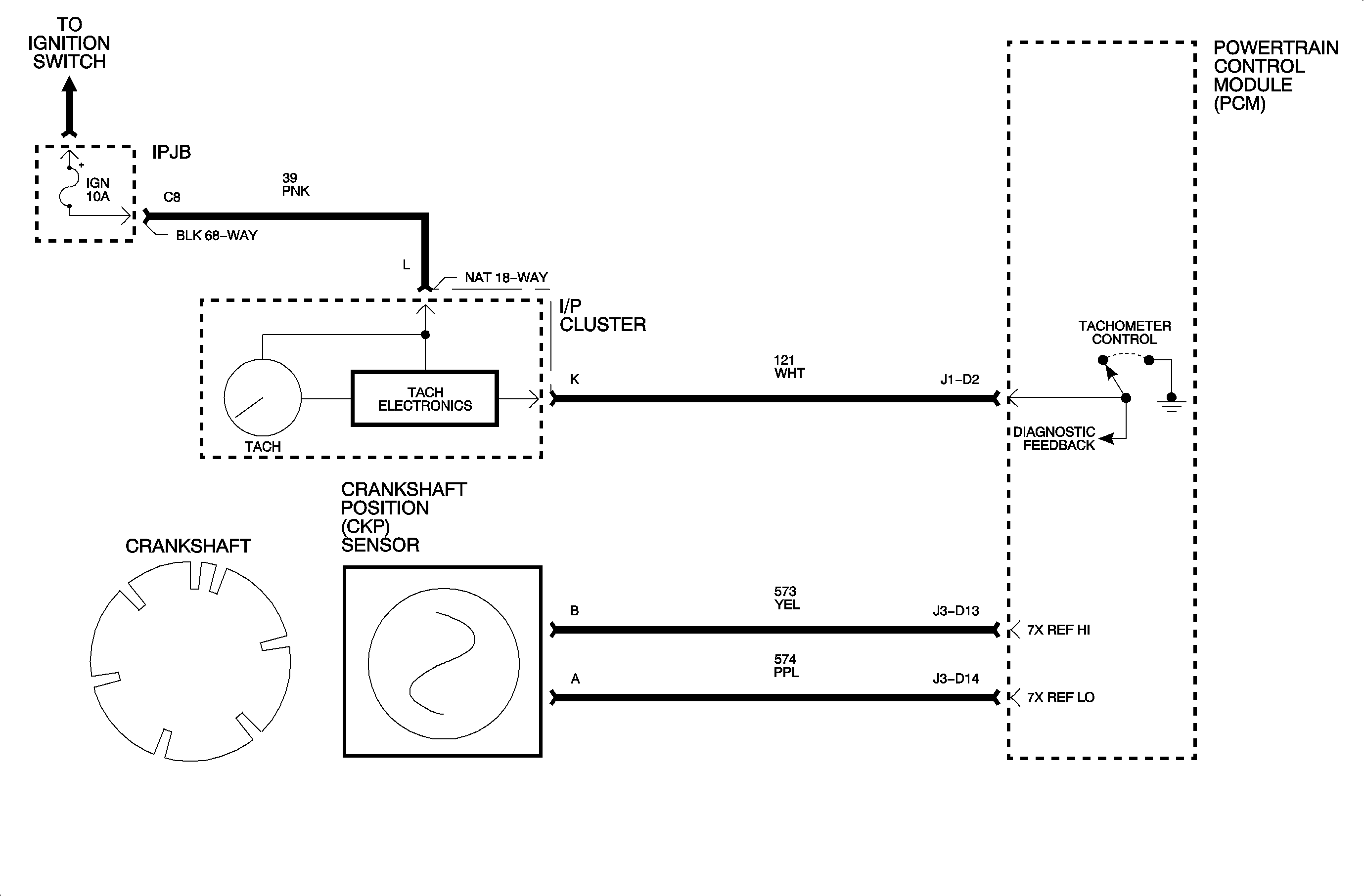
DTC P1336 - CRANKSHAFT NOTCH ADAPTIVE NOT LEARNED

CRANKSHAFT NOTCH ADAPTIVE NOT LEARNED
The PCM receives signals from the crankshaft positive sensor to determines the position of the crankshaft at various degrees of rotation. The PCM can then base misfire diagnostics on the principle that crankshaft velocity will increases as each cylinder contributions its power input. The PCM must know precisely the degree of variability in crankshaft notches to perform the misfire diagnosis functions. Replacement of either the PCM or the crankshaft requires a "crankshaft learn" procedure to learn the variability of the crankshaft notches. DTC P1336 will set if the learn procedure has not been performed and the vehicle is driven.
DTC PARAMETERS
DTC P1336 will set if the crankshaft notch learn process has not been completed and the vehicle is driven above 15 mph (24 kph).
Important: Do not transfer PCMs from one vehicle to another without resetting the crankshaft adaptives and performing the crankshaft learn procedure. The learned notches will be different from one vehicle (crankshaft) to another. Failure to perform this procedure may result in false misfire detection.
Important: Anytime a crankshaft position sensor is replaced, the crankshaft learn procedure must be performed.
DIAGNOSTIC AIDS
| • | The crankshaft notch learn routine will not run if misfire conditions are detected. If any other DTCs are present, diagnose and repair those first. When finished with repairs, perform the "crankshaft learn" procedure. |
| • | View Scan tool parameter "crankshaft learned" in misfire table. The tool will indicate Yes when learned procedure is complete. |
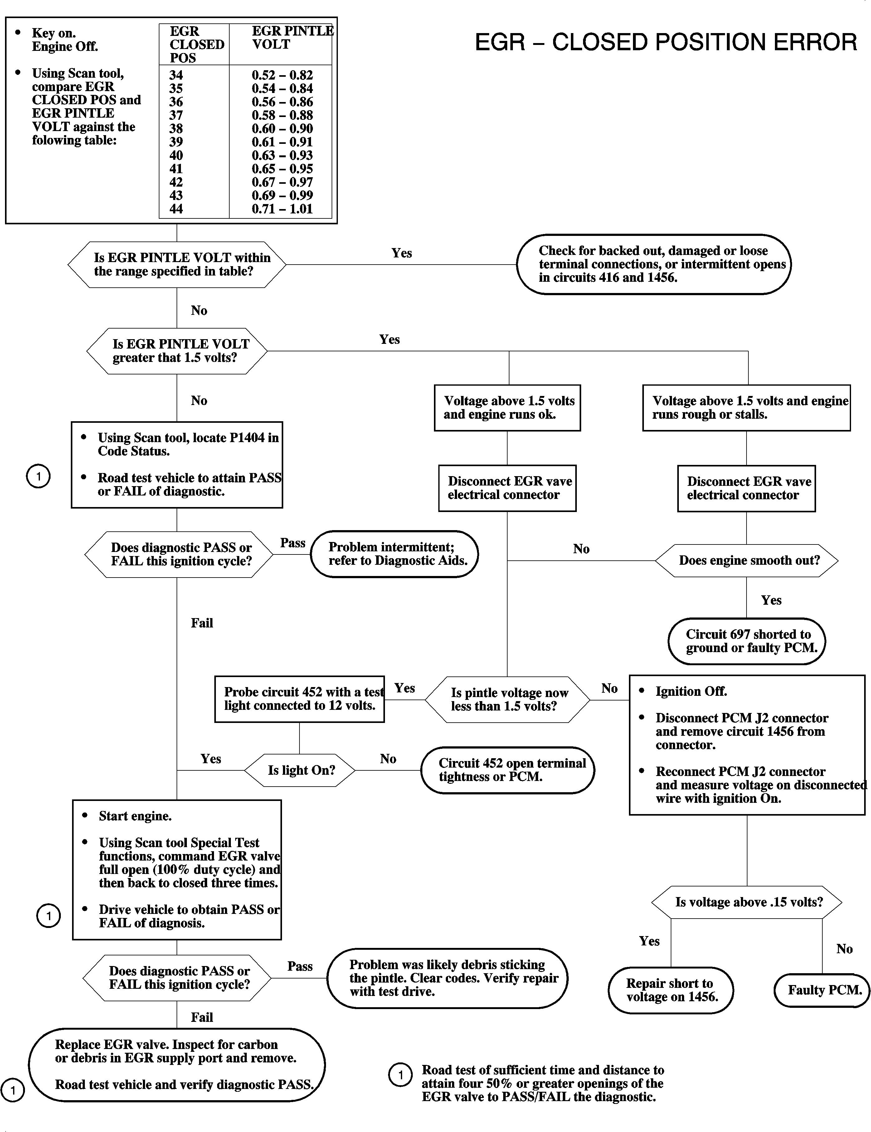
DTC P1404 EGR - CLOSED POSITION ERROR

EGR - CLOSED POSITION ERROR
The linear EGR system consists of a linear EGR valve, the PCM and its associated wiring. The EGR valve solenoid is controlled directly by the PCM when certain conditions have been met. The PCM contains a diode feedback circuit which dissipates energy when the valve is cycled Off. When the PCM commands the EGR valve closed, a closed valve position value is learned. If the PCM commands the valve closed and the actual feedback value does not match the learned value. DTC P1404 will set.
DTC PARAMETERS
DTC P1404 will set when the actual closed value does not match the learned closed value within 20 seconds if;
| • | RPM is below 5000 an the actual vs learned is greater than 0.2 volts, or |
| • | RPM is above 5000 and the actual vs learned is greater than 0.4 volts. |
Important: If DTCs P0405 are also set, begin diagnosis with these DTCs first. Do not clear codes until diagnosis is completed.
Important: When the PCM recognizes that the parameters for setting P1404 have been set, the diagnostic software waits until the EGR cycles open 50% or greater four times and then retests. If after the four cycles the actual vs learned is not within the parameters, the DTC will be stored and MIL (SERVICE ENGINE SOON) will be commanded on.
Important: When this DTC sets, functions will be disabled. When repairs are complete, codes must be cleared and ignition keyed off for at least 10 seconds to allow proper operation.
DIAGNOSTIC AIDS
| • | Check for backed out or damaged terminals. |
| • | Check for a stuck open EGR pintle. Inspect EGR pintle valve bore for carbon or debris and remove. Verify that the pintle closed. |
| • | An open in circuit 452 will result in P1404. |
| • | A short to ground n circuit 697 will result in a severe rough idle and driveability complaint and set a P1404. |
| • | Check for backed out damaged, poor terminal tightness or an intermittent open in circuits 416 or 1456. |

