Tools Required
J 43628 Frame Alignment Fixture
Removal Procedure
- Raise the vehicle on a hoist.
- Remove the HO2S from the heat shield.
- Disconnect the HO2S electrical connector.
- Remove the HO2S.
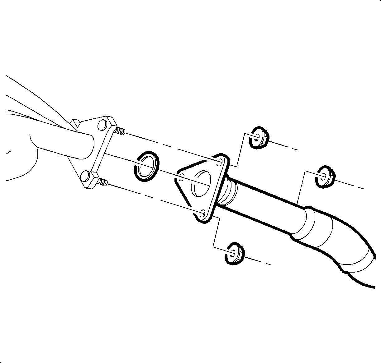
- Remove the exhaust manifold pipe to exhaust manifold fasteners.
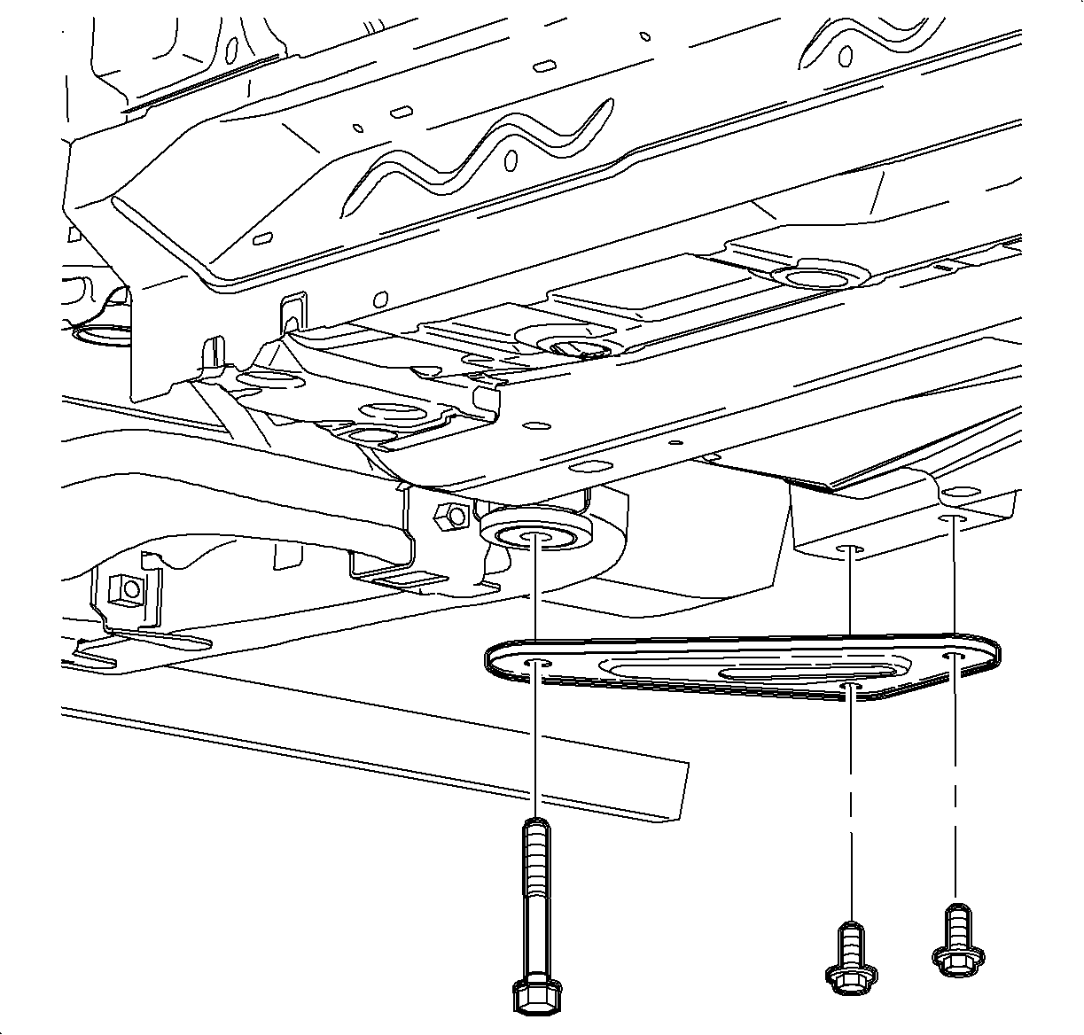
- Remove the suspension support assemblies and discard the bolts.
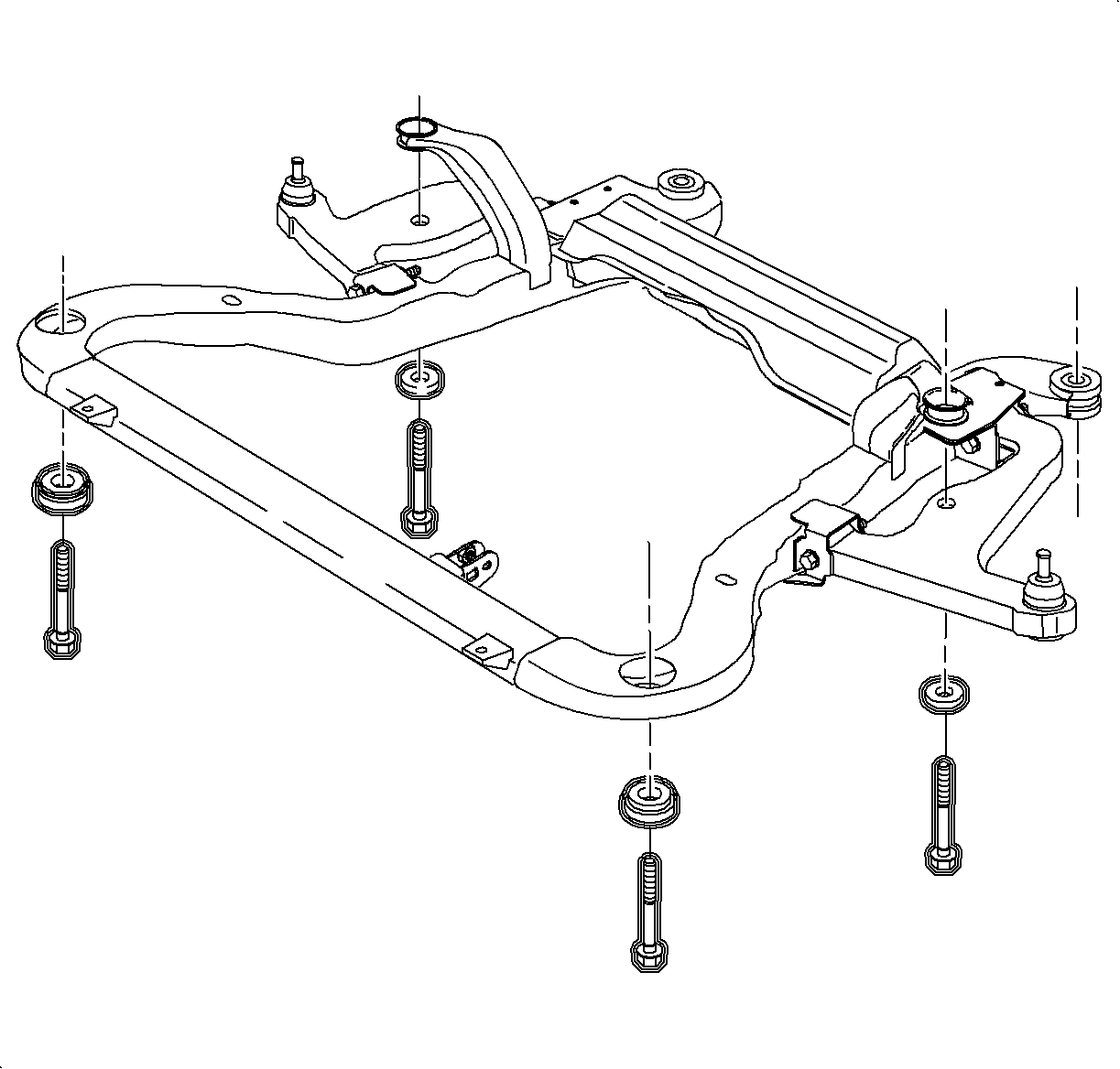
- Loosen the remaining frame attachment fasteners to allow clearance for the exhaust manifold pipe flange to pass by the frame.
- Remove the exhaust manifold pipe to exhaust/resonator fasteners.
- Remove the exhaust manifold pipe.
Caution: Refer to Vehicle Lifting Caution in the Preface section.
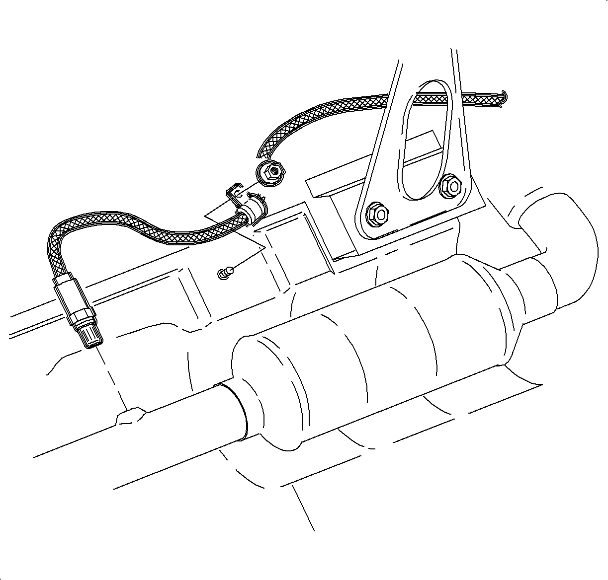
Important: Do not apply grease or silicon products to the heated oxygen sensor (HO2S) 2. Do not alter the wiring in any way. The wires carry air reference to the sensor.
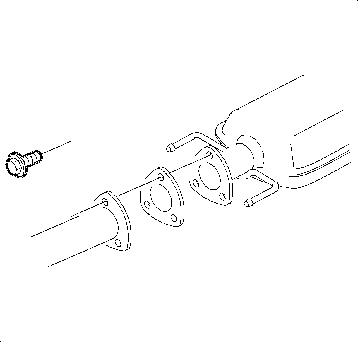
Installation Procedure
- Position the gasket on the manifold pipe.
- Position the manifold pipe into the vehicle.
- Install the exhaust manifold pipe to exhaust manifold nuts.
- Position the gasket between the manifold pipe and resonator.
- Install the exhaust manifold pipe to resonator bolts and tighten.
- Tighten the exhaust manifold pipe to exhaust manifold nuts.
- Install the J 43628 , or equivalent, and raise the frame to the vehicle.
- Remove the remaining frame bolts and replace with new bolts and tighten.
- Install the new cage nuts into the body for the suspension supports, as torque retention of old nuts may not be sufficient.
- Install the suspension supports using new bolts and tighten.
- Install the HO2S.
- Connect the HO2S harness connector.
- Connect the HO2S harness to heat shield.
- Lower the vehicle from the hoist.
- Start the engine and check for exhaust leaks.

Important: Do not tighten the fasteners.

Notice: Refer to Fastener Notice in the Preface section.
Tighten
Tighten the exhaust manifold pipe-to-resonator bolts
to 20 N·m (15 lb ft).
Tighten
Tighten the exhaust manifold pipe-to-exhaust manifold
nuts to 30 N·m (22 lb ft).
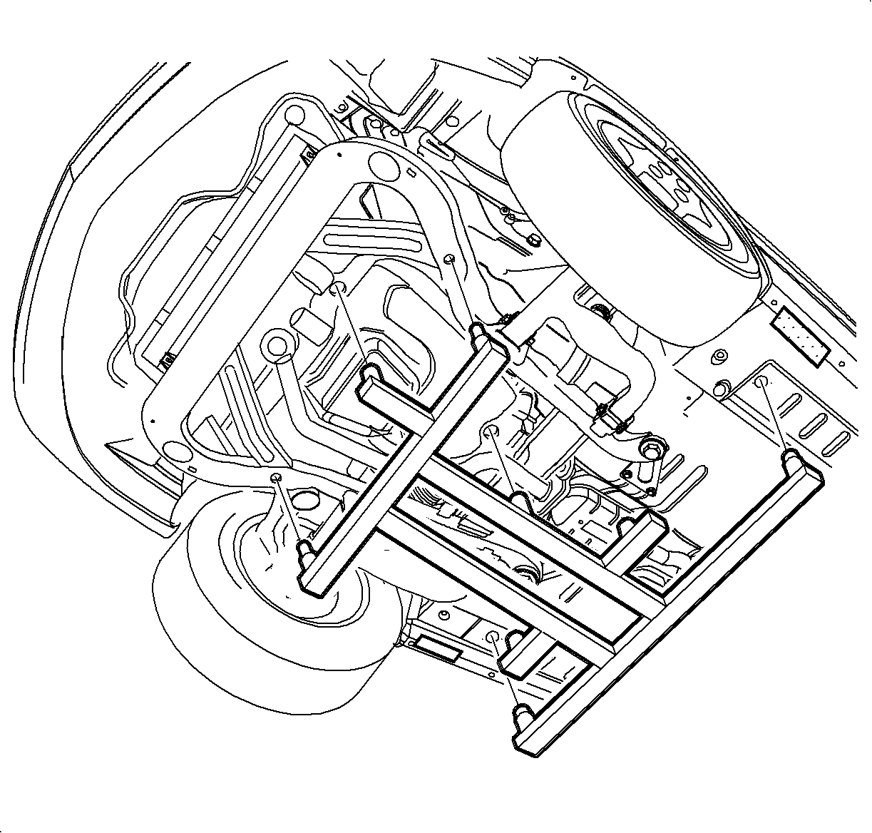

Tighten
Tighten the frame-to-body bolts to 100 N·m
(74 lb ft) plus 45 degrees plus 60 degrees.

Tighten
Tighten the suspension support-to-body bolts to
90 N·m (60 lb ft) plus 45 degrees plus 60 degrees.
Notice: Always use a nickle-based anti-seize compound Saturn P/N 21485279 (or equivalent) on the threads of the heated oxygen sensor (H02S-2). If the H02S-2 is replaced, do not apply anti-seize to the new sensor. New sensors have anti-seize pre-applied. Never use silicone products. Silicone products will damage the sensor.
Tighten
Tighten the HO2S 2 sensor-to-exhaust pipe
to 45 N·m (33 lb ft).
Tighten
Tighten the HO2S 2 harness clip-to-heat shield
bolt to 4 N·m (35 lb in).
