For 1990-2009 cars only
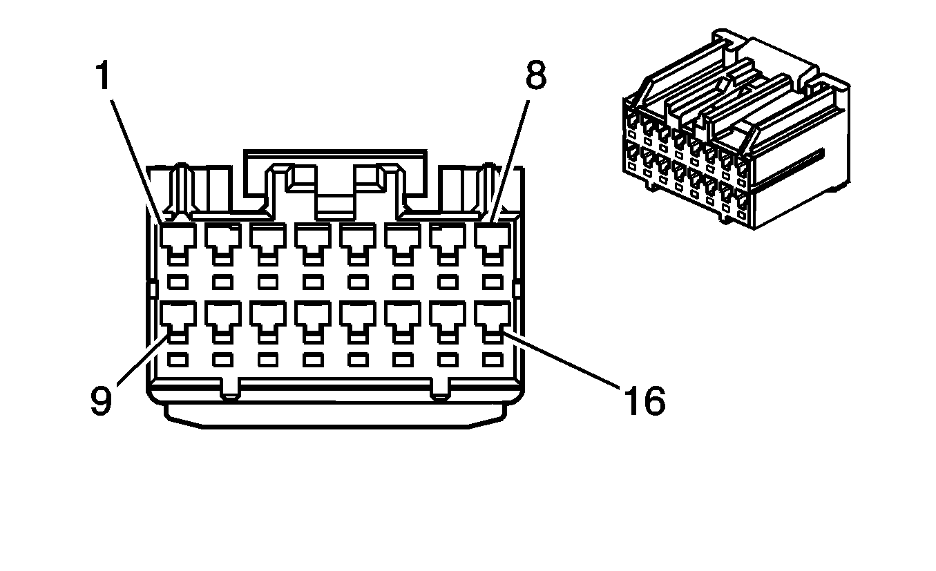
| Table 1: | Inside Rearview Mirror (ISRM) |
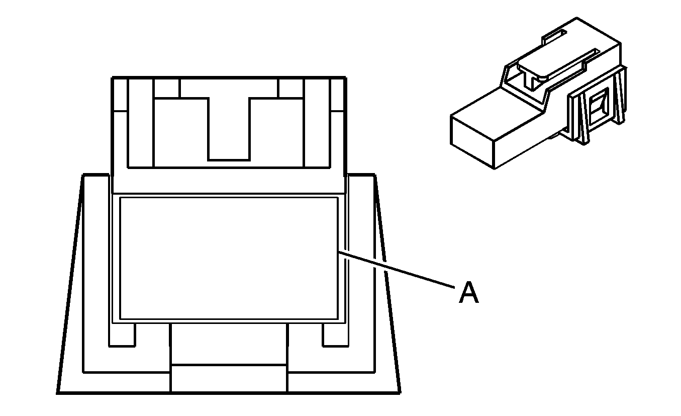
| Table 2: | Rear Defogger Grid - C1 |
| Table 3: | Rear Defogger Grid - C2 |

| |||||||
|---|---|---|---|---|---|---|---|
Connector Part Information |
| ||||||
Pin | Wire Color | Circuit No. | Function | ||||
1-5 | -- | -- | Not Used | ||||
6 | OG | 1732 | Courtesy Lamps Supply Voltage | ||||
7 | -- | -- | Not Used | ||||
8 | BK | 450 | Ground | ||||
9 | L-GN | 24 | Backup Lamps Supply Voltage | ||||
10 | -- | -- | Not Used | ||||
11 | BN | 2514 | Keypad Signal (UE1) | ||||
12 | D-BU | 2515 | Keypad Supply Voltage (UE1) | ||||
13 | YE | 743 | Ignition 1 Voltage | ||||
14 | GY | 2516 | Keypad Green LED Signal (UE1) | ||||
15 | BN/WH | 2517 | Keypad Red LED Signal (UE1) | ||||
16 | -- | -- | Not Used | ||||

| |||||||
|---|---|---|---|---|---|---|---|
Connector Part Information |
| ||||||
Pin | Wire Color | Circuit No. | Function | ||||
A | PU | 293 | Rear Defog Element Supply Voltage | ||||

| |||||||
|---|---|---|---|---|---|---|---|
Connector Part Information |
| ||||||
Pin | Wire Color | Circuit No. | Function | ||||
A | BK | 750 | Ground | ||||
