For 1990-2009 cars only
Removal Procedure
- Raise and support the vehicle. Refer to Lifting and Jacking the Vehicle in General Information.
- Remove the tire and wheel. Refer to Tire and Wheel Removal and Installation in Tires and Wheels.
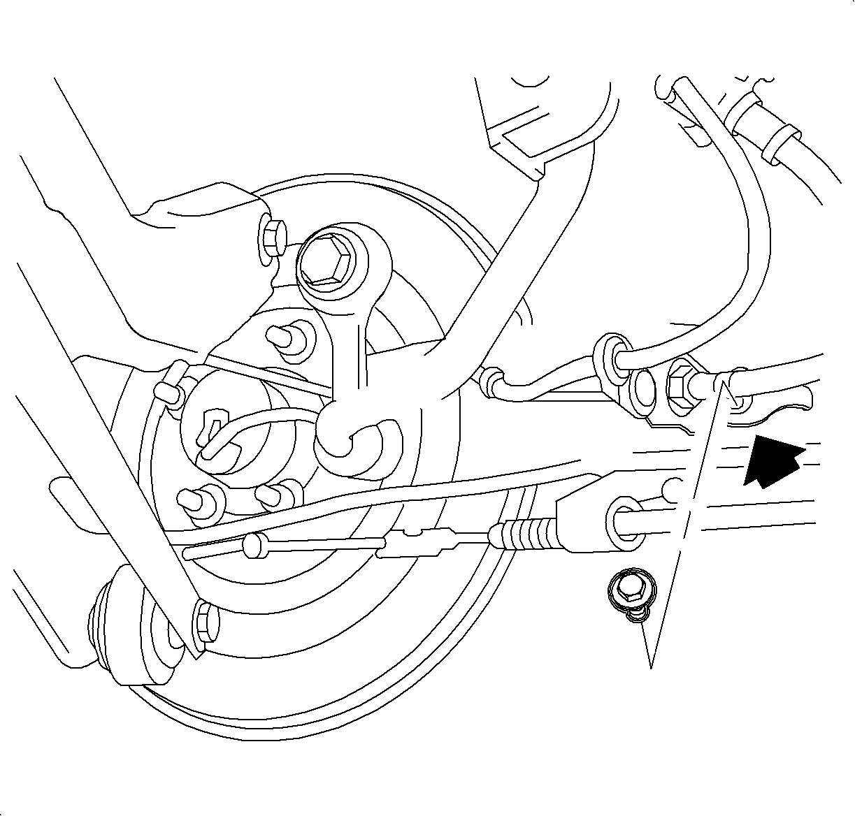
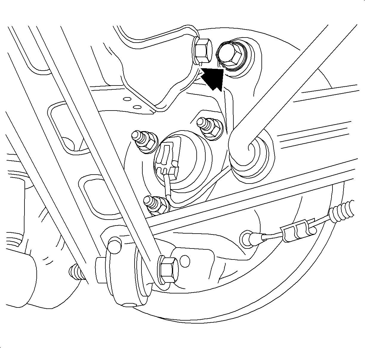
- Remove the rear brake hose bracket from the trailing arm.
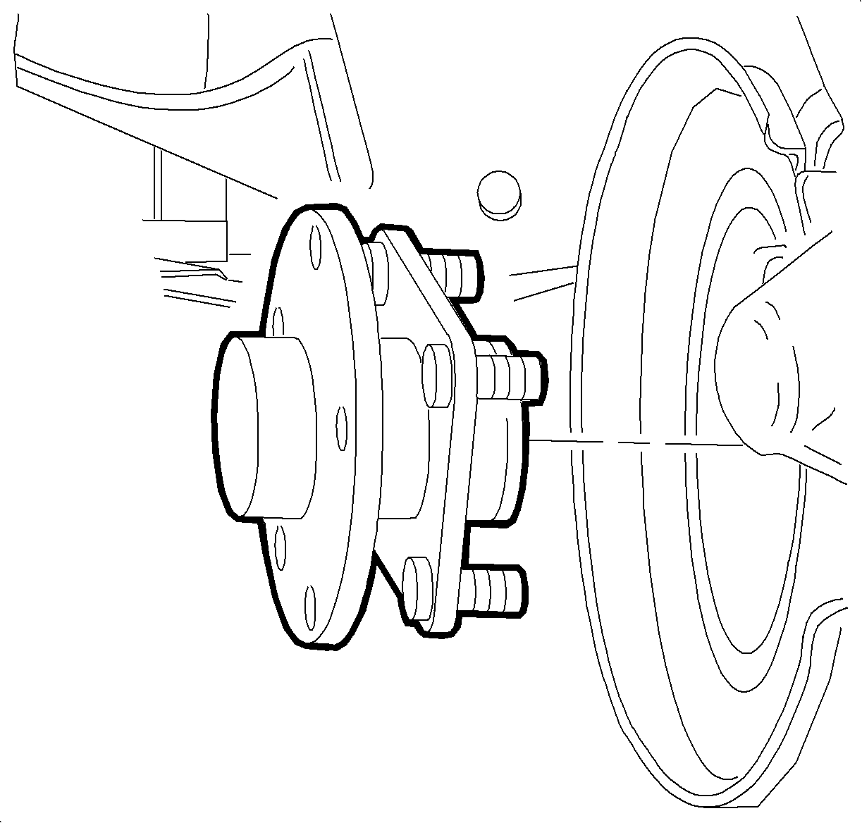
- Remove the wheel bearing/hub assembly. Refer to Rear Wheel Bearing and Hub Replacement .
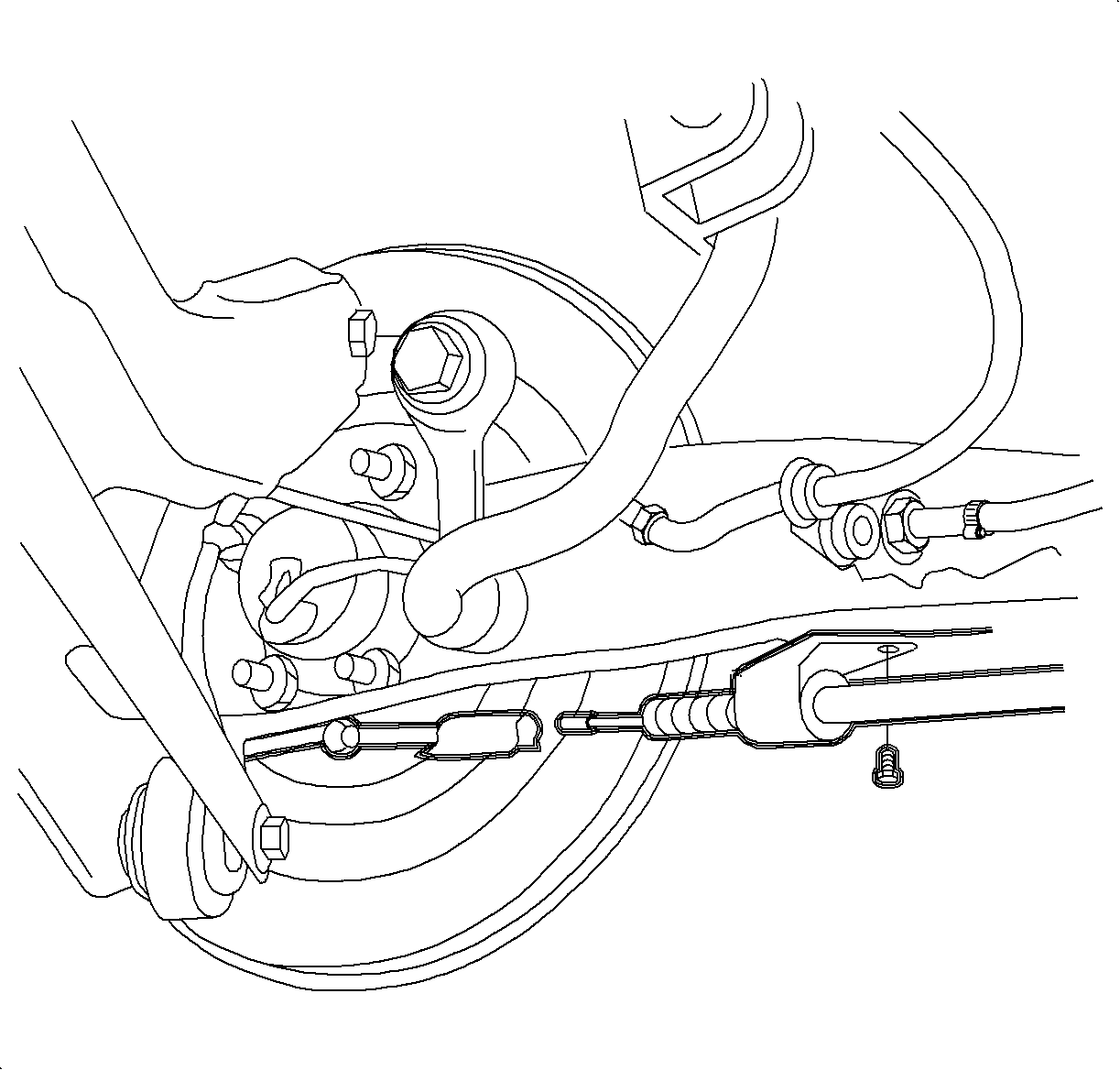
- Disconnect the brake cable support from the parking brake cable.
- If equipped with drum brakes, separate the backing plate from the control arm. Secure the backing plate when disconnected.
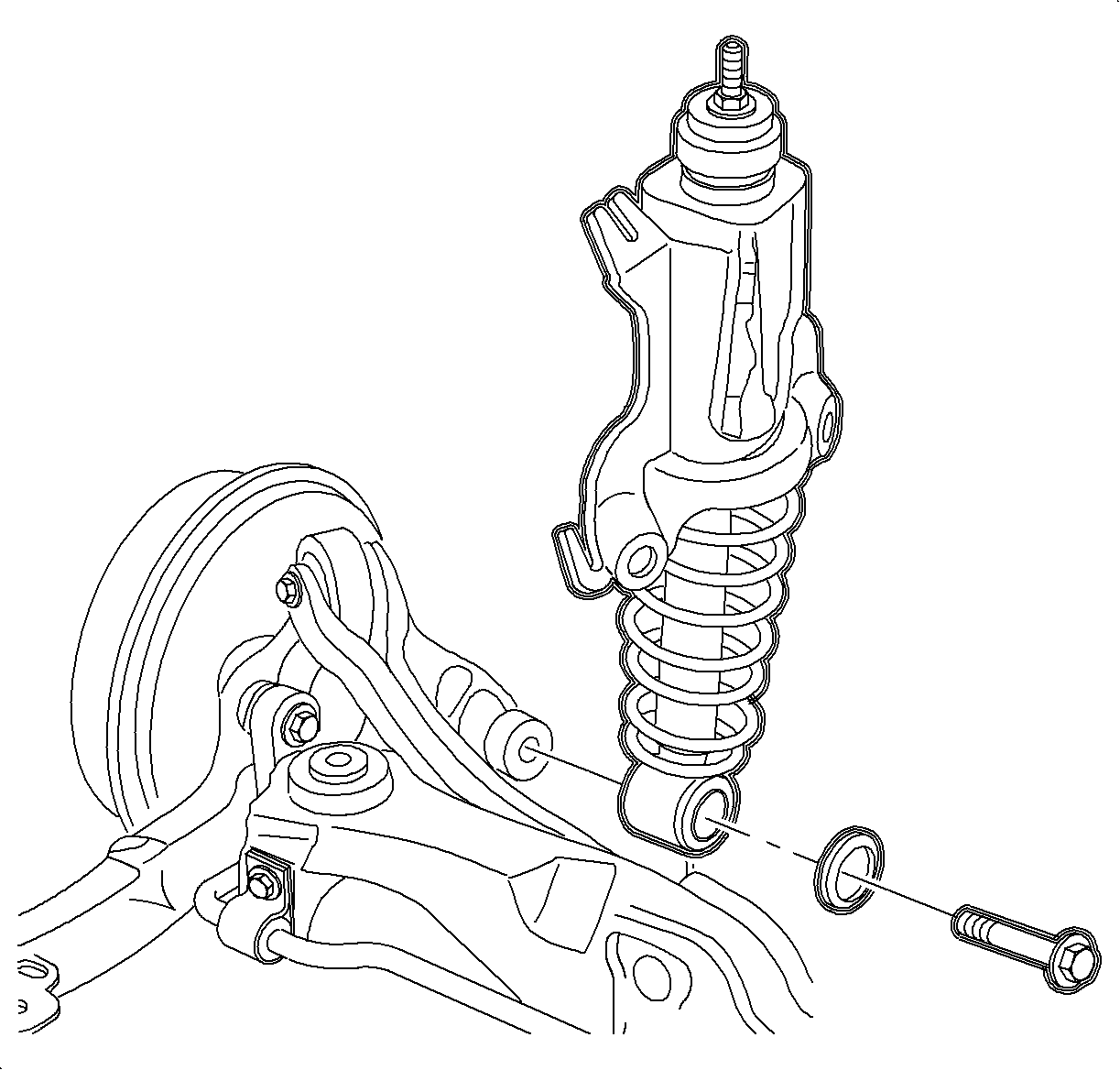
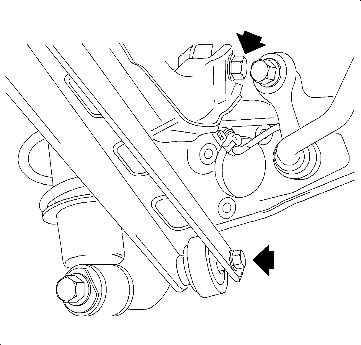
- Remove the shock assembly to trailing arm bolt. Discard the bolt.
- Remove the stabilizer link to trailing arm bolt.
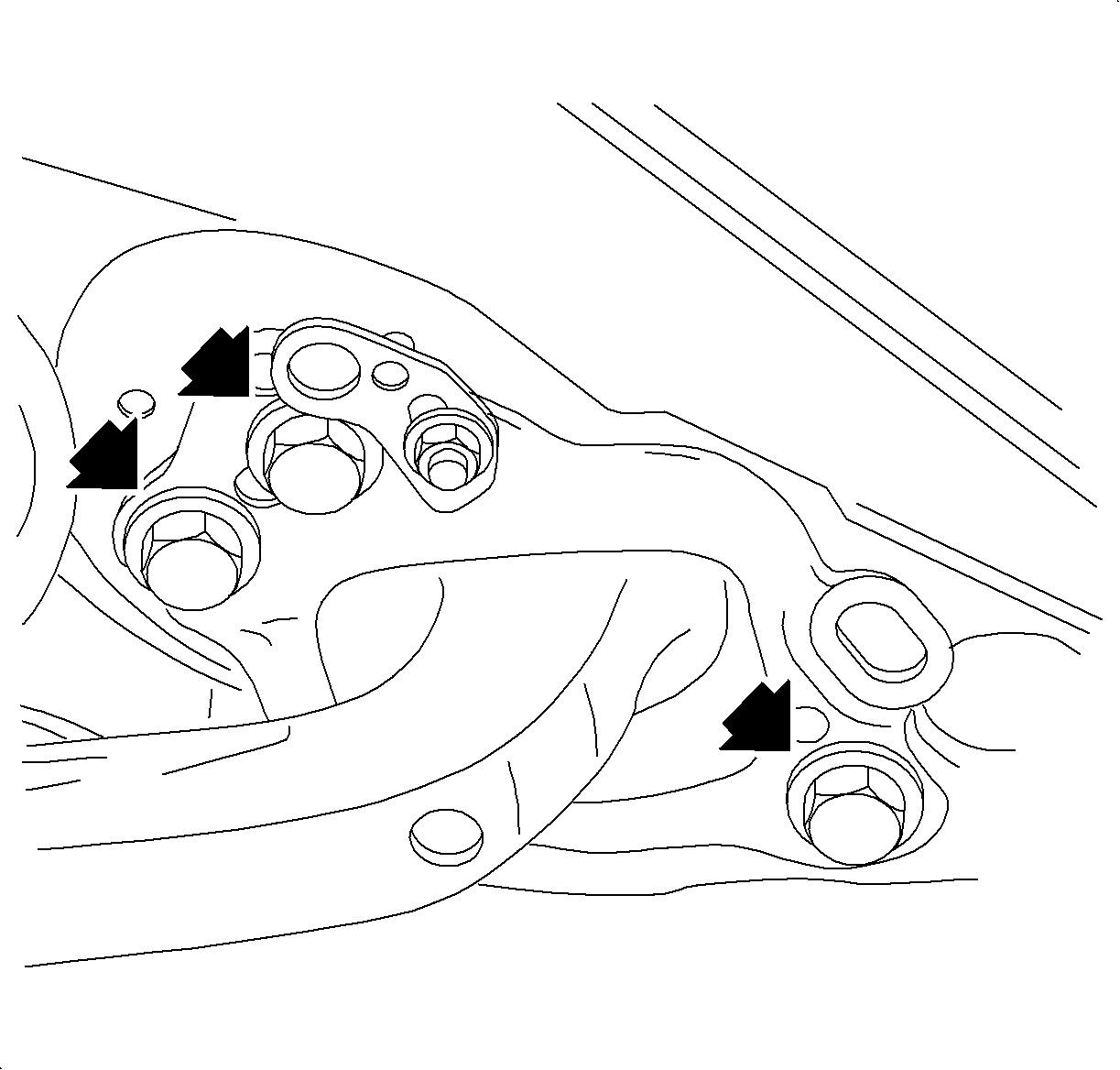
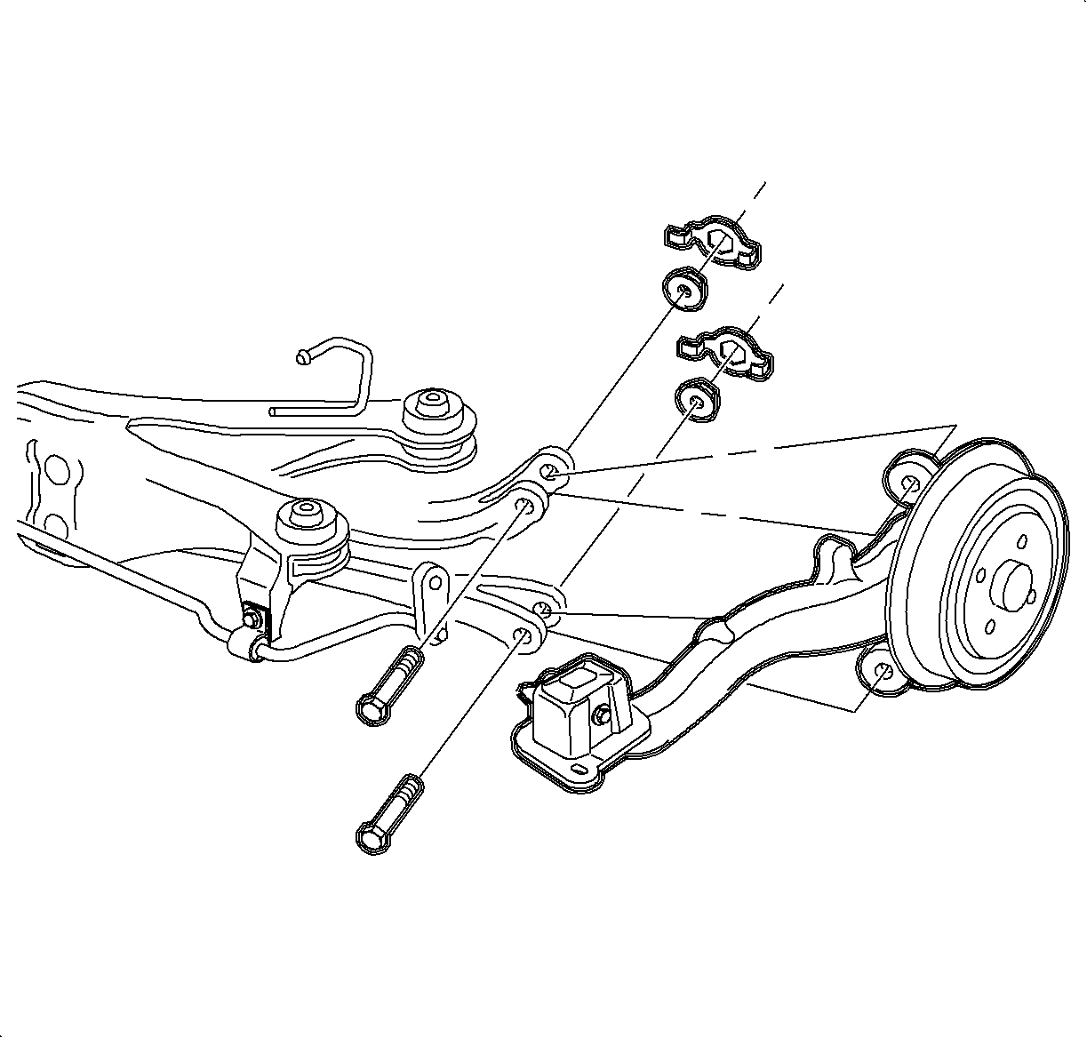
- Loosen the upper and lower control arm to trailing arm bolts.
- Remove the trailing arm to body bolts. Discard the bolts.
- Remove the upper and lower control arm to trailing arm bolts and nuts. Discard the bolts and nuts.
- Remove the trailing arm from the vehicle.
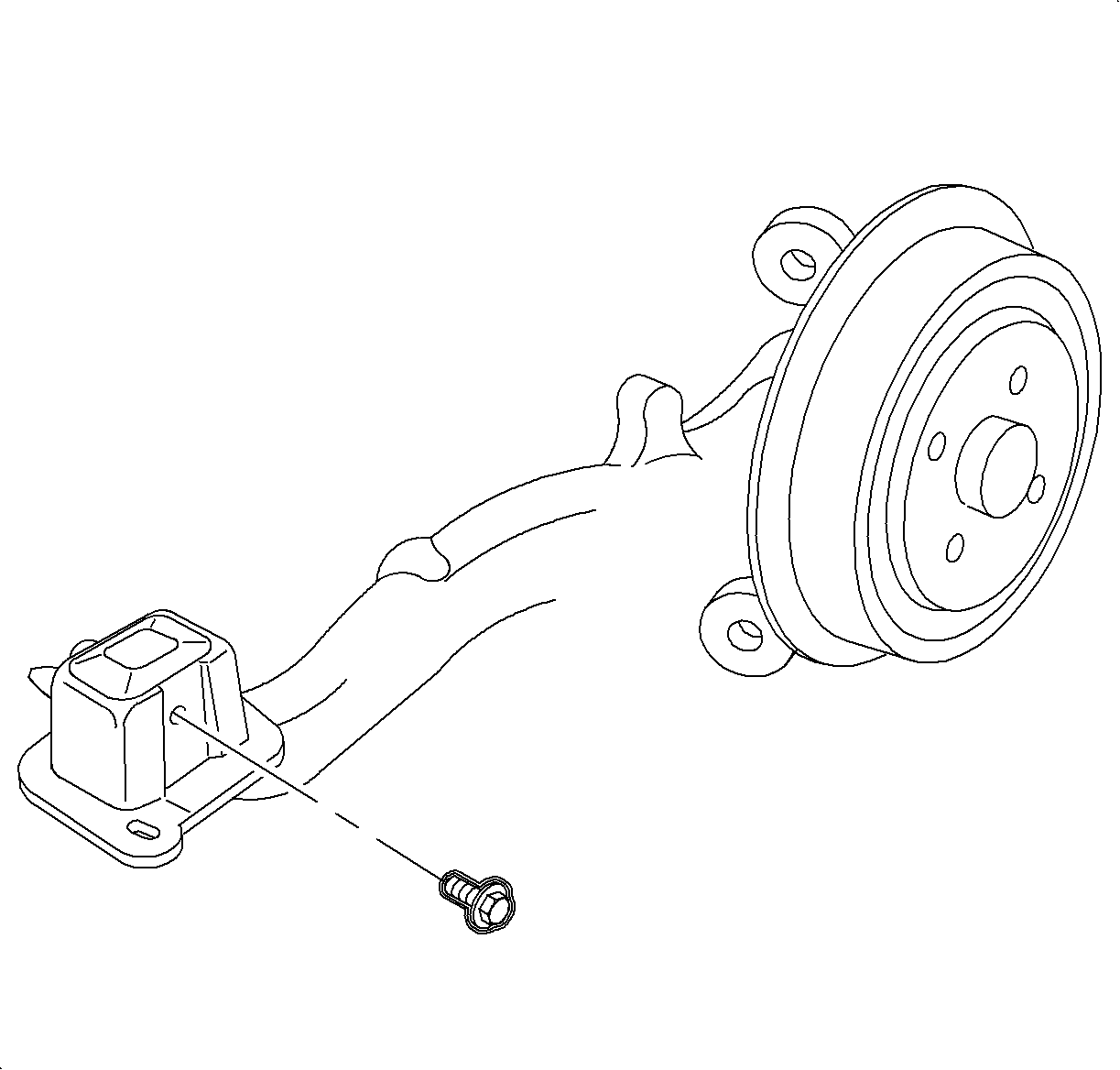
- Place the control arm in a suitable vise.
- Remove the trailing arm bracket bolt and nut. Discard the bolt and nut.
- Remove the trailing arm from the trailing arm bracket.
Installation Procedure
- Install the trailing arm in the trailing arm bracket.
- Install a new trailing arm bracket bolt and nut.
- Position the trailing arm into the vehicle.
- Install new trailing arm to body bolts. Hand tighten only.
- Using new nuts and bolts connect the upper and lower control arms to the trailing arm. Hand tighten only.
- Tighten the trailing arm bracket to body bolts.
- Tighten the upper and lower control arm bolts.
- Install the shock assembly to the trailing arm.
- Connect the stabilizer link to the trailing arm.
- If equipped with drum brakes, install the rear brake backing plate.
- Install the wheel bearing/hub assembly and brake components. Refer to Rear Wheel Bearing and Hub Replacement .
- Install the brake cable support to the parking brake cable.
- Install the parking brake cable bracket to the trailing arm.
- Install the brake line bracket to the trailing arm.
- Install the tire and wheel. Refer to Tire and Wheel Removal and Installation in Tires and Wheels.
- Lower the vehicle.
- Inspect for an alignment. Refer to Wheel Alignment Measurement in Wheel Alignment.

Notice: Refer to Fastener Notice in the Preface section.
Tighten
Tighten the bolt and nut to 90 N·m
(66 lb ft).

Tighten
Tighten the bolts to 90 N·m (66 lb ft).
Tighten
Tighten the nuts and bolts to 90 N·m
(66 lb ft).

Tighten
Tighten the bolt to 150 N·m (110 lb ft).

Tighten
Tighten the bolt to 55 N·m (41 lb ft).
Tighten
Tighten the bolt to 50 N·m (37 lb ft)
plus an additional 30 to 45 degrees.


Tighten
Tighten the bolt to 8 N·m (71 lb in).

Tighten
Tighten the bolt to 8 N·m (71 lb in).
