For 1990-2009 cars only
Removal Procedure
- Disable the SIR System. Refer to SIR Disabling and Enabling in Sir. Pull up on the control boot until the indicator bezel disengages from the console.
- Remove the console. Refer to Console Replacement .
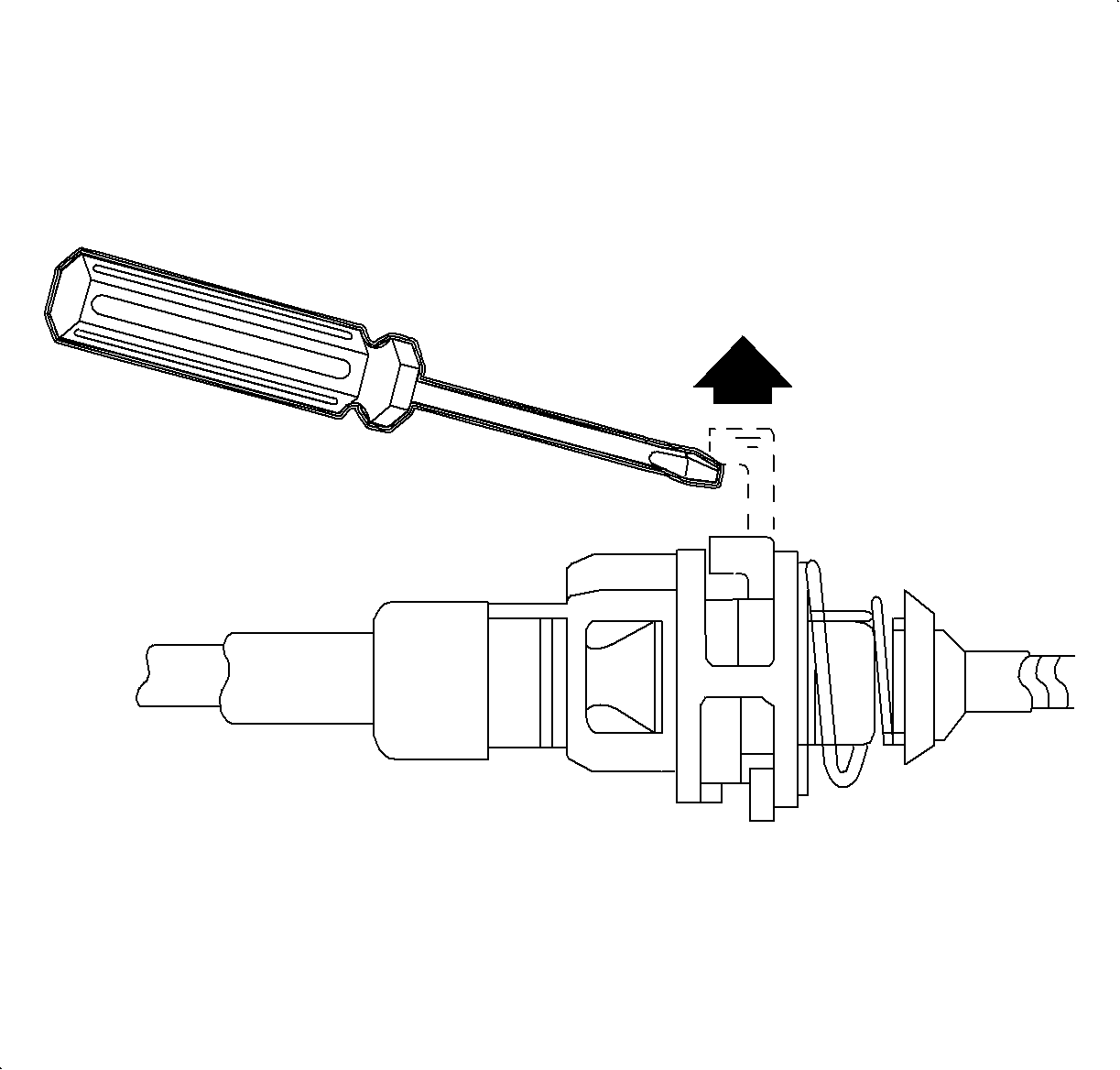
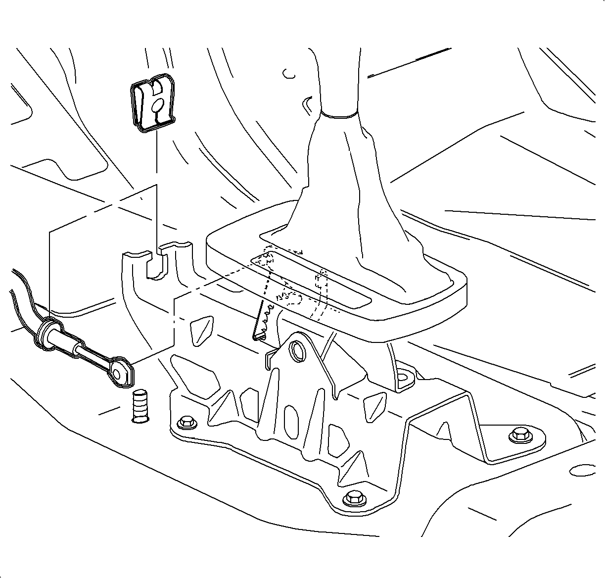
- Using a screwdriver, disconnect the control cable from the control assembly.
- Disconnect the electrical connector from the indicator bezel.
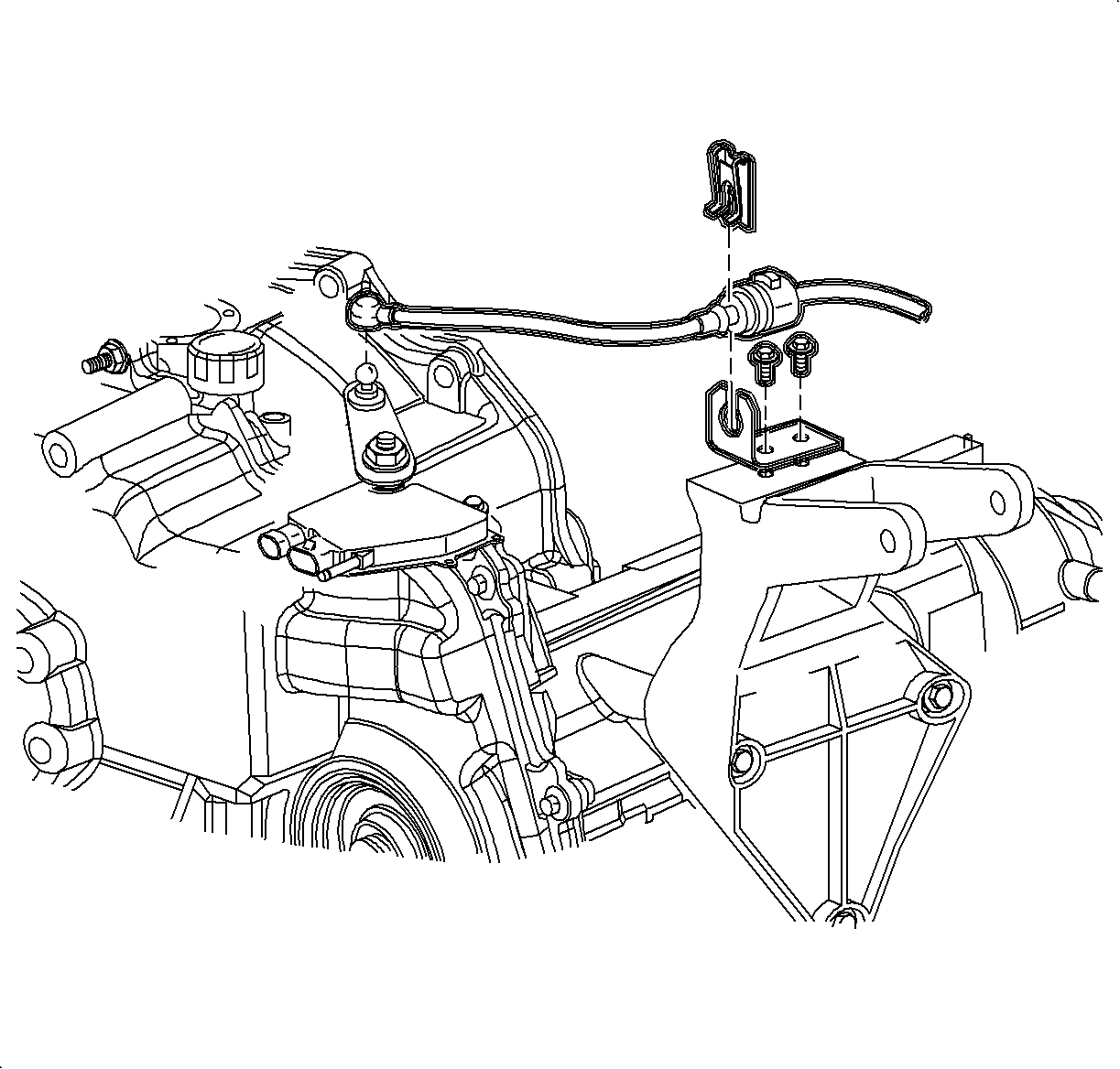
- Remove the control cable retaining clip.
- Press the tabs on the control cable and remove the cable from the control assembly.
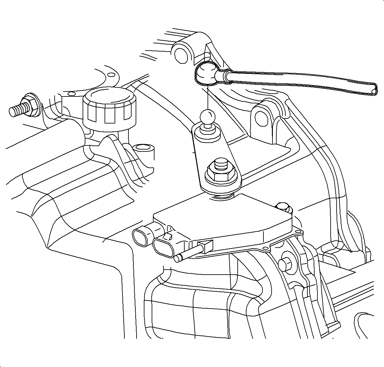
- Disconnect the control cable from the transaxle range switch lever.
- Remove the control cable retaining clip.
- Press the 2 tabs on the control cable and remove the cable from the control cable bracket.
- Remove the control cable grommet from the dash panel.
- Remove the control cable from the vehicle.
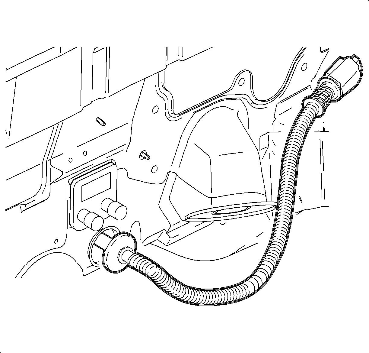
Installation Procedure
- Guide the control cable through the pass-through in the dash panel.
- Secure the control cable grommet by pressing the cable into the pass-through hole in the dash panel.
- Route the control cable through the cable bracket on the powertrain mount, and secure the cable into the bracket.
- Install the control cable retaining clip.
- Connect the control cable end to the control assembly lever.
- Connect the control cable to the pin on the control assembly.
- Secure the control cable into the control assembly by pushing into place.
- Install the control cable retaining clip.
- Install the console. Refer to Console Replacement .
- Adjust the control cable assembly. Refer to Shift Lock Control Cable Replacement .
- Enable the SIR system. Refer to SIR Disabling and Enabling in Sir .


Adjustment Procedure
- Move the control assembly into the PARK position.
- Disconnect the control cable from the transaxle range switch lever.
- Make sure the transaxle range switch lever is in the PARK position by moving the lever counterclockwise, away from the dash panel, until it clicks and can not be moved any further.
- Release the control cable assembly adjustment lock tab at the control cable bracket on the rear powertrain mount. Use a screwdriver, awl, or pick to pry up the lock tab and lift.
- Connect the control cable end to the transaxle range switch lever.
- Press the lock tab on the control cable assembly.
- Verify proper operation.
