For 1990-2009 cars only
Removal Procedure
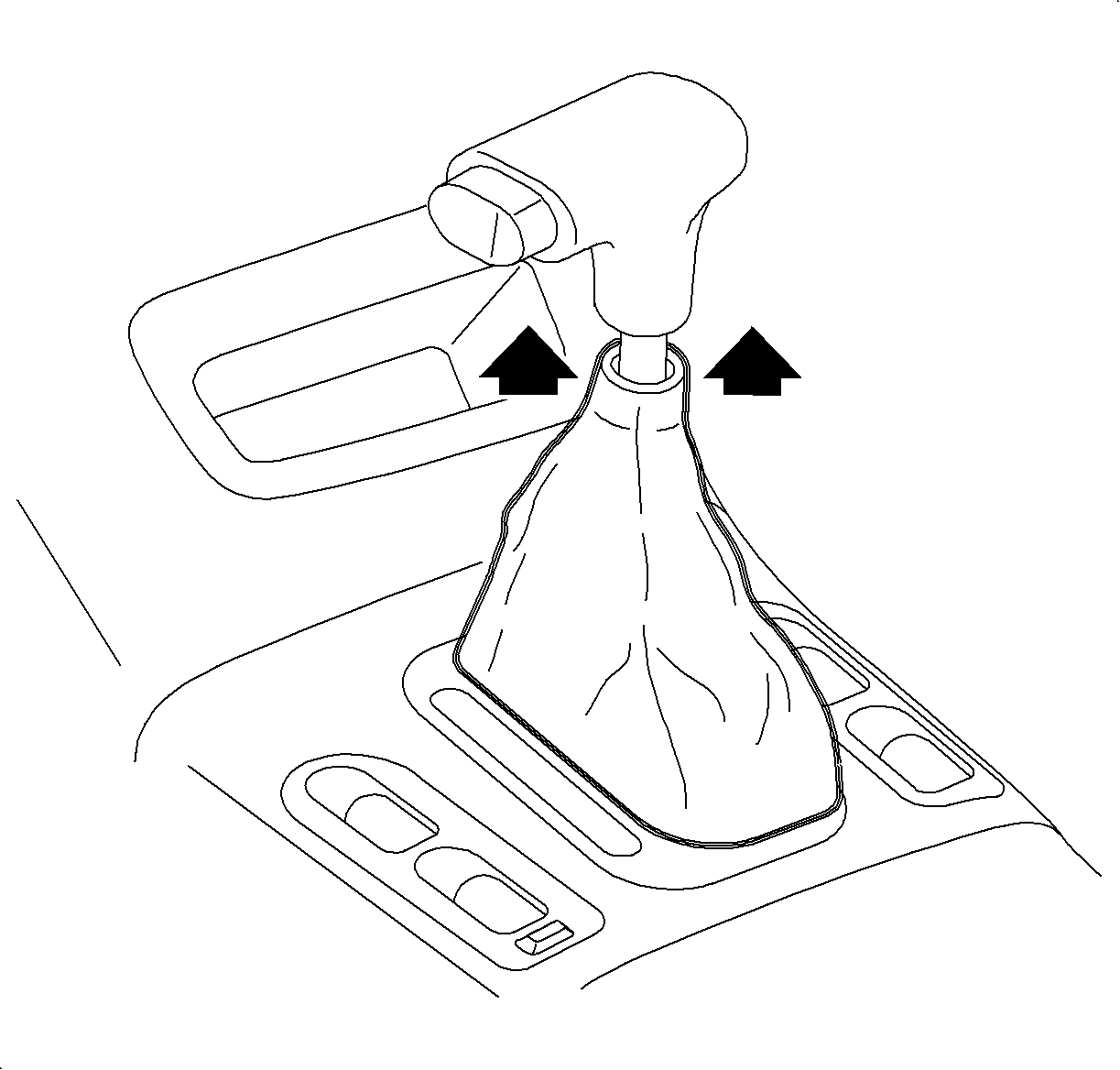
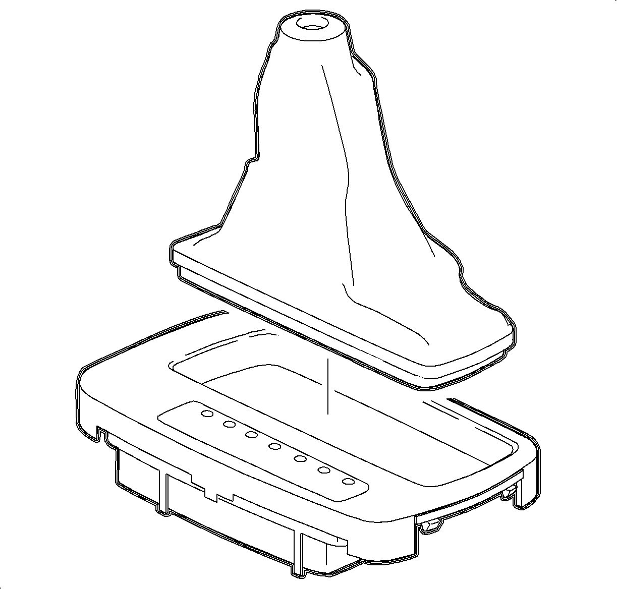
- Pull the control assembly boot down to disengage the boot from the knob.
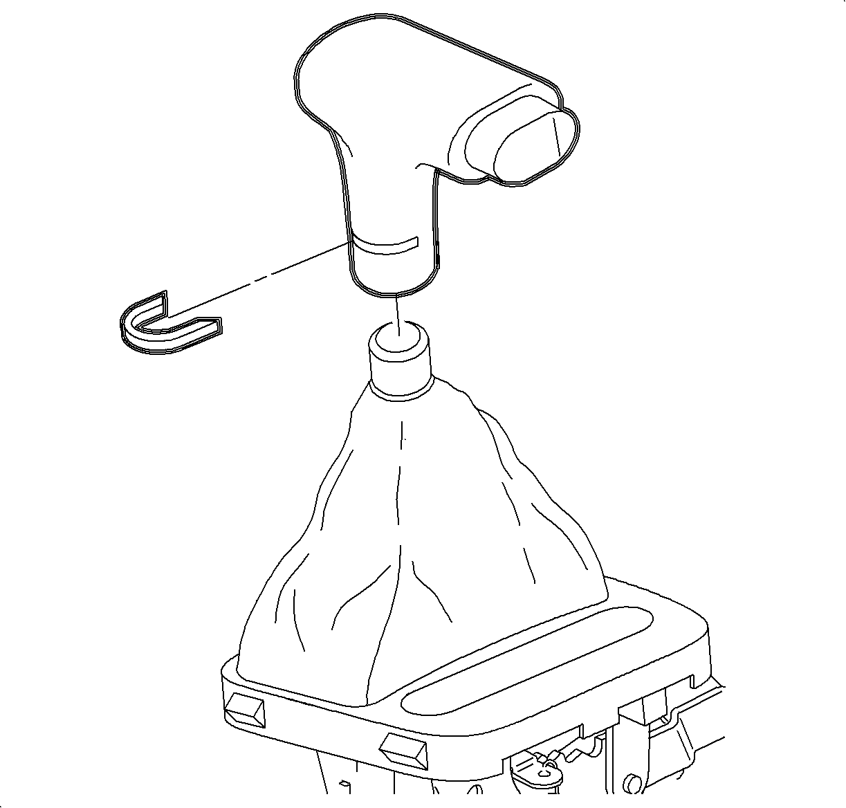
- Using a screwdriver, remove the control lever knob retainer. Remove the control lever knob.
- Pull up on the control boot until the indicator bezel disengages from the console.
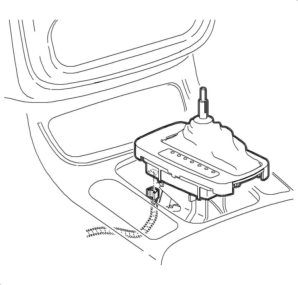
- Disconnect the indicator bezel electrical connector. Remove the bezel and boot.
- Disengage the control boot from the indicator bezel from the underside of the bezel. Remove the boot.
Installation Procedure
- Install the control boot into the indicator bezel.
- Install the bezel and boot over the shift lever and connect the indicator bezel electrical connector. Snap the bezel into the console opening.
- Install the control lever knob and the knob retainer.
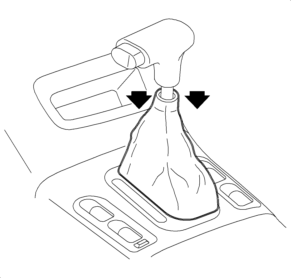
- Install the control assembly boot onto the knob so the O-ring in the top of boot is seated in the groove on the bottom of the knob.


