For 1990-2009 cars only
Stabilizer Shaft Replacement W/L61
Removal Procedure
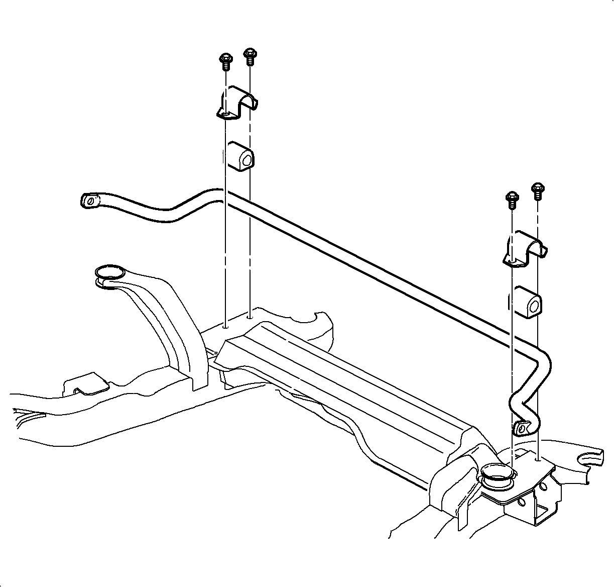
- Remove the stabilizer shaft clamp to frame bolts.
- Raise and support the vehicle. Refer to Lifting and Jacking the Vehicle in General Information.
- Remove the front tires and wheels. Refer to Tire and Wheel Removal and Installation in Tires and Wheels.
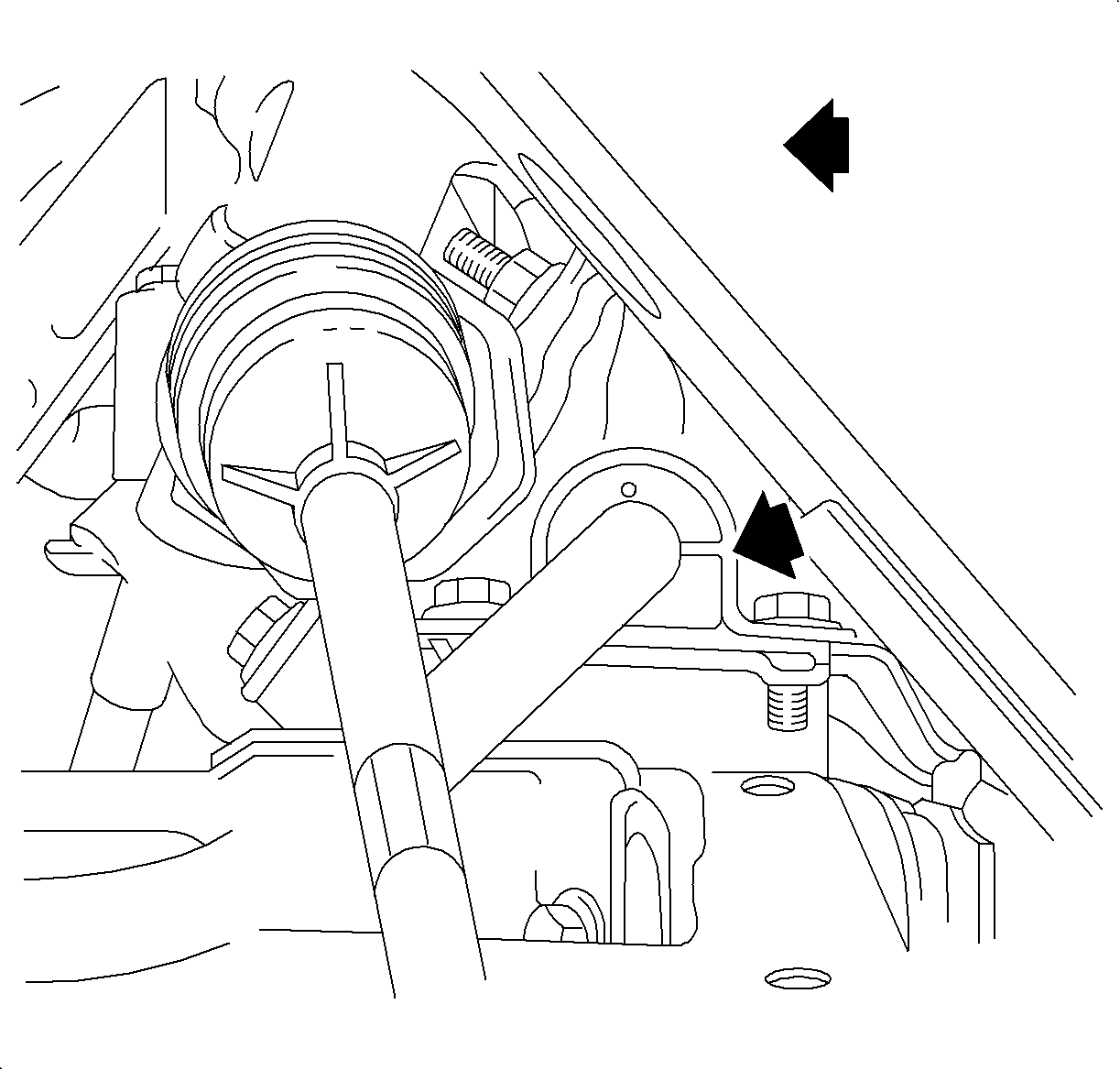
- If equipped with a manual transmission, remove the exhaust manifold pipe. Refer to Exhaust Manifold Pipe Replacement in Engine Exhaust.
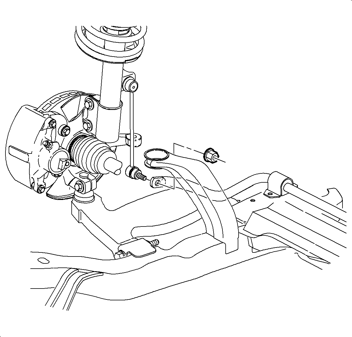
- Disconnect the stabilizer shaft links from the stabilizer shaft. Refer to Stabilizer Shaft Link Replacement .
- Remove the stabilizer shaft through the left wheel opening.
- Remove the stabilizer insulators from the stabilizer shaft.


Installation Procedure
- Install the stabilizer shaft bushings to the stabilizer shaft.
- Install the stabilizer shaft through the left wheel opening.
- Install the stabilizer shaft clamps, hand tighten at this time.
- If equipped with cruise control, tighten the left stabilizer clamp bolts.
- Connect the stabilizer links to the stabilizer shaft.
- If equipped with a manual transmission, install the exhaust manifold pipe. Refer to Exhaust Manifold Pipe Replacement in Engine Exhaust.
- Install the front tires and wheels. Refer to Tire and Wheel Removal and Installation in Tires and Wheels.
- Lower the vehicle.
- Install the remaining stabilizer shaft clamp to frame bolts.

Important: The stabilizer shaft bushings must be installed with the slot facing forward.
Notice: Refer to Fastener Notice in the Preface section.

Tighten
Tighten the bolts to 20 N·m (15 lb ft).

Important: Do not allow the stabilizer link ball stud to rotate when tightening the ball stud nut.
Tighten
Tighten the nuts to 65 N·m (48 lb ft).

Tighten
Tighten the bolts to 20 N·m (15 lb ft).
Stabilizer Shaft Replacement W/L81
Removal Procedure
- Remove the stabilizer shaft clamp to frame bolts.
- Raise and support the vehicle. Refer to Lifting and Jacking the Vehicle in General Information.
- Remove the front tires and wheels. Refer to Tire and Wheel Removal and Installation in Tires and Wheels.
- Remove the exhaust manifold pipe. Refer to Exhaust Manifold Pipe Replacement in Engine Exhaust.
- Disconnect the stabilizer shaft links from the stabilizer shaft. Refer to Stabilizer Shaft Link Replacement
- Remove the stabilizer shaft through the left wheel opening.
- Remove the stabilizer insulators from the stabilizer shaft.


Installation Procedure
- Install the stabilizer shaft bushings to the stabilizer shaft.
- Install the stabilizer shaft through the left wheel opening.
- Install the stabilizer shaft clamps, hand tighten at this time.
- Connect the stabilizer links to the stabilizer shaft.
- Install the exhaust manifold pipe. Refer to Exhaust Manifold Pipe Replacement in Engine Exhaust.
- Install the front tires and wheels. Refer to Tire and Wheel Removal and Installation in Tires and Wheels.
- Lower the vehicle.
- Tighten the stabilizer shaft clamp to frame bolts.

Important: The stabilizer shaft bushings must be installed with the slot facing forward.

Notice: Refer to Fastener Notice in the Preface section.

Important: Do not allow the stabilizer link ball stud to rotate when tightening the ball stud nut.
Tighten
Tighten the nuts to 65 N·m (48 lb ft).

Tighten
Tighten the bolts to 20 N·m (15 lb ft).
