Radio Head
The radio head faceplate interfaces with the operator through control buttons/knobs,
a liquid crystal display (LCD), a four channel integrated amplifier, and playback
mechanisms (CD and/or tape). The controls operate various music modes and conditions
of the audio subsystem which enable the operator to control power, volume, fade, balance,
bass, and treble equalization settings, along with media playback control (CD or tape).
The LCD is located in the center of the radio head faceplate for the operator to see
the feedback from the radio. The radio head processes AM or FM stereo signals from
the antenna system and sends the output to the speakers. The radio head also processes
and plays the pre-recorded music from the in-dash CD and/or tape playback mechanism
or the remote CD changer. The tape mechanism is able to differentiate between FeO2
(Type 1) or CrO2 (Type II/IV) type tapes. The functions of the playback mechanism
(CD or tape) are controlled by the controls on the radio head faceplate.
The radio head is located in the middle of the instrument panel and is fastened
using two chassis side-mounted brackets which utilize two fasteners and two rubber
pins (one on each side of the radio opening) for locating the radio. The radio head
is electrically connected to the radio I/P harness via a 24-way connector for base
and up-level radios. There is also a 12-way connector for up-level radios to connect
the CD changer/player jumper connector. A ground strap terminal and an antenna connector
are located on the rear side of the radio head unit. The harness connector(s), antenna
connector, and ground strap are inserted prior to mounting the radio in the vehicle.
To allow for radio serviceability, sufficient room is allocated behind the radio for
the wires and the coax cable.
The clock time is displayed continuously even when the ignition is OFF. Back
lighting of the display occurs when the ignition is ON. If the RCL button is pressed
when the ignition is OFF, then the LCD back lighting will be ON temporarily.
Radio Ground Strap
There is a ground strap attached to the radio to ensure an effective ground
path. The ground strap is a braided copper wire that routes from the rear of the radio
to the brace behind the radio. The radio ground strap is connected to the radio by
a spade type terminal. If the radio ground strap is not reconnected after being disconnected
for service, the audio system will still function, but the sound quality will be reduced.
CD Changer/Player (Optional)
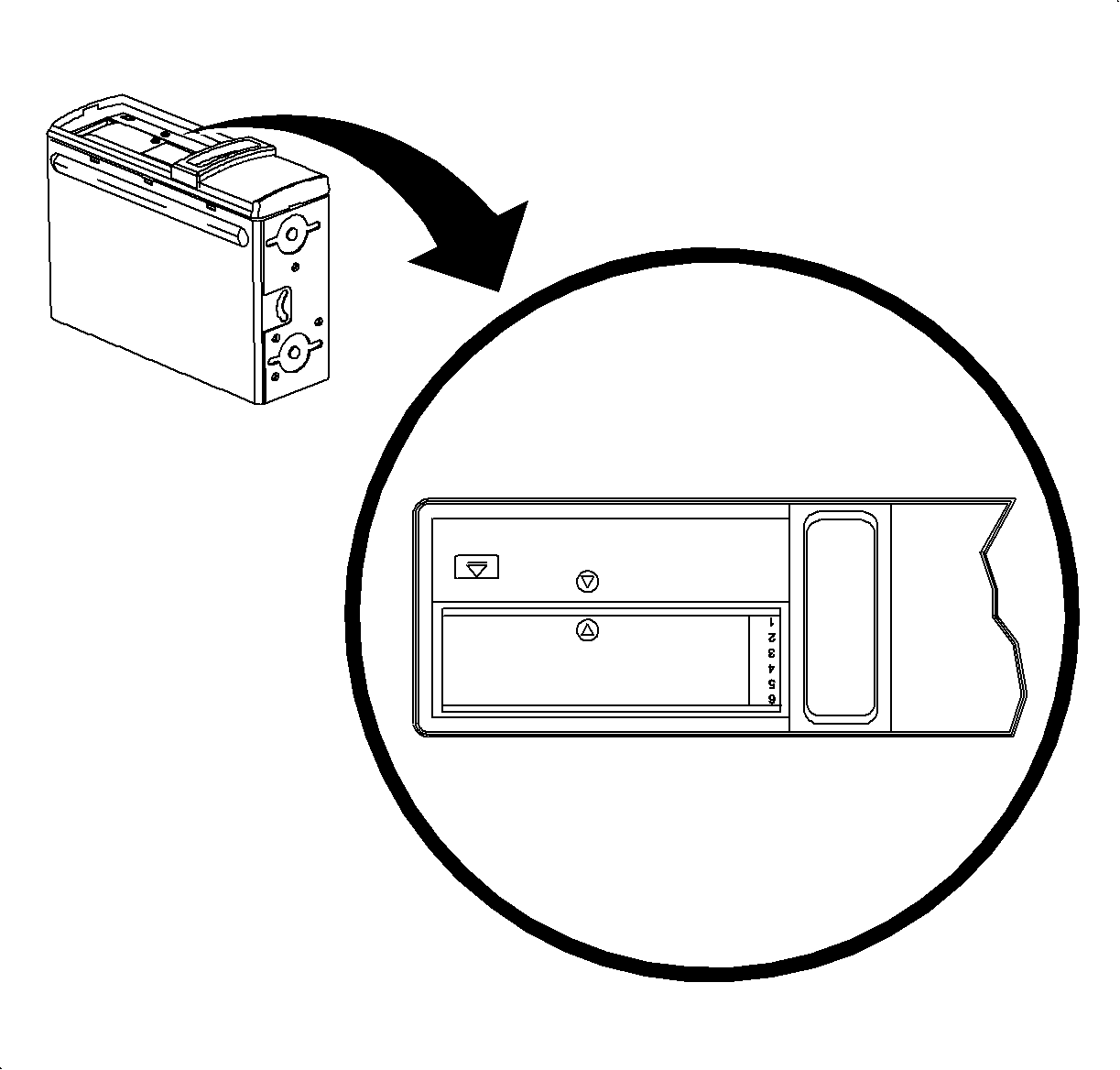
The 6-disc remote CD changer/player with magazine is mounted to the right side
rear underbody sheet metal. The CD changer/player is vertically mounted with the CD
changer/player door opening closest to the front of the vehicle. To ensure CD changer/player
skip performance the CD changer/player is mounted rigidly.
The remote CD changer/player has a separate fuse from the radio and receives
its power and signals through the radio. The CD changer/player has a wiring jumper
connected between the radio and CD changer/player with one inline between and includes
shielding for the audio signals. The CD changer/player is available only with up-level
radios. If a customer with a base radio would like a CD changer/player, that customer
must upgrade their radio to an up-level radio (either the AM/FM tape or the AM/FM
tape and CD).
Speaker Sound System Interface
The speakers receive information from the radio in the form of electrical current
through the speaker wires. The electrical current produces the electromagnetic forces
which cause the speaker cone to move, which in turn creates acoustical energy. The
acoustical energy radiates from the speakers and is received by the operator as sound.
If the speaker wires occasionally become shorted-to-ground or to vehicle power, the
radio will sense these conditions and shut down in a non-destructive manner. After
the short condition is removed, normal radio operation will return.
The speakers are angled upward and rearward for optimal sound performance. They
are mounted to a flat door inner surface and provide a splash proof housing and seal
through the use of a gasket on the speaker basket flange that meets the door inner
sheet metal. The speakers are closed out to the trim from the front. The supporting
structure is rigid as to not allow unwanted resonance or loss in bass frequencies.
Grilles are used to protect the speaker covering since they allow the speaker the
freedom to move and breath to make the performance more predictable. The minimum speaker
impedance per channel is four ohms and the interface to the speakers is through 18
gage wire (for up-level audio sound system only) or 16 gage (for advanced audio sound
subwoofer only) through the body harness. The speakers are mounted low and forward
in each of the four doors.
Up-Level Audio Sound Speaker System
The up-level audio sound system consists of eight speakers. In each of the four
doors, there is both a 0.75 inch tweeter and a woofer (6 inch HSS in the front doors
and 5 inch HSS in the rear doors).
Advanced Audio Sound Speaker System
The advanced audio sound system consists of seven speakers and an amplifier.
There is a 0.75 inch tweeter in each of the front doors, a woofer in all four doors
(6 inch ERS speaker in each front door and 5 inch ERS speaker in each
rear door), and a 5 inch subwoofer (located on the rear shelf panel for the sedan.
In the wagon, the subwoofer is mounted to the left side wheelhouse area). The amplifier
module is found attached to the I/P beam. The supporting structures are rigid as to
not allow unwanted resonance or loss in bass frequencies for both the subwoofers and
the amplifier.
The amplifier contains all of the necessary signal processing and power amplifier
circuitry that is not contained within the radio and has dedicated battery circuits,
a battery fuse, and ground circuits for its power source. The wiring from the radio
outputs to the amplifier inputs consist of a harness containing four twisted pairs,
one for each audio channel. The radio also supplies a switched battery control signal
to the amplifier for the purpose of controlling the module's ON/OFF modes. The speaker
outputs are not grounded, but are protected against accidental grounding or connecting
to battery.
Antenna System
The antenna system receives broadcast AM or FM stereo signals from free space
and sends the signals to the radio receiver for processing via a coaxial antenna cable.
The antenna cable is a coax cable, which connects the radio to the antenna. The antenna
ground should not exceed 50 m ohms when measuring between the antenna connector shield
and negative battery terminal. The antenna mast should be installed to the torque
specification specified in the Removal and Installation section so that it will not
become loose and fall off. In the United States, the AM broadcast is 530-1710 KHz
in 10KHz steps while the FM broadcast is 87.9-107.9 MHz in 200 KHz steps.
The sedan and wagon have different antennas. The sedan uses a mast antenna mounted
on the left rear side of the vehicle. The wagon has a rear roof mounted antenna.
Antenna System (Sedan Only)
The sedan fixed mast antenna has a single 1/4 wave monopole receiving
element which protrudes from the vehicle. The antenna is mounted on the left rear
quarter panel area sheet metal via a bracket attached to the wheelhouse inner. The
fixed mast antenna directly receives RF signals and feeds the signal directly to the
radio head for processing.
Antenna System (Wagon Only)
The wagon active roof antenna system uses a single short monopole receiving
element which is mounted to the rear roof sheet metal of the vehicle. The passive
roof antenna directly receives RF signals, processes these signals, and sends them
to the radio receiver.
Customer Tips
How To Enjoy FM Stereo
| • | Select Stations Within Range - The best FM fidelity will be obtained
from stations within a 16-64 km (10-40 mi) range. Beyond that range noise
or flutter may begin to appear due to the line of sight range limitations of FM signals. |
| | Solution - Reduce treble response by moving the treble control to a lower
setting in fringe areas. |
| • | Realize Tall Structures Can Interfere - Tall buildings or hills
may cause shadows or cancellation of FM signals. This is similar to the ghost or flutter
effect seen on television sometimes when airplanes are flying in the vicinity. It
will sound like a pop or momentary hiss. |
| | Solution - Reduce the treble to a lower setting. |
| • | Interference From Another Station - Although the circuits in receivers
are the most advanced available, there are rare instances where a station being listened
to will be interfered with by another station. This only happens when the stations
are on almost the same frequency and certain geographical criteria are present. |
| | Solution - Select another station or switch to tape or CD. |
Handling The Compact Disc Magazine
Care Of Compact Disc Magazine
| • | Do not put the CD magazine in a place where it will be exposed to high
temperatures or direct sunlight. |
| • | Do not knock the CD magazine against anything. |
| • | Never insert anything other than CDs into the CD magazine. |
| • | Never insert a CD with a label or tape attached to it. |
| • | Do not use an 8 cm CD without a special 8 cm (3 in)
disc adapter (not available through Saturn Service Parts). |
| • | The use of benzene, thinner, insecticide, or other volatile chemicals
may damage the CD magazine surface. Clean only with a clean, damp, soft, lint-free
cloth and a mild, neutral detergent. |
Extra Magazines
Extra CD magazines are available through Saturn Service Parts.
Removing CD Magazine From CD Changer/Player
To eject the CD magazine from the CD changer/player, slide the CD changer/player
door all the way open until it locks with a click. Press the CD changer/player eject
button. The CD changer/player will load the last played CD back into the CD magazine,
and the CD magazine will automatically eject.
Loading CD Magazine Into CD Changer/Player
- After the desired number of CDs are installed in the CD magazine, insert
the CD magazine with arrow pointing toward the arrow on the CD changer/player.
- Close the door of the CD changer/player by sliding it closed until it
clicks.
- The CD changer/player will then begin checking CDs in the CD magazine.
The initialization period lasts for approximately 20 seconds, depending on the number
of CDs loaded. If a CD has been loaded incorrectly, it could take up to 60 seconds
to initialize.
Cleaning The CD Changer/Player
Cleaning the CD changer/player is not recommended. The CD lens is very sensitive
to scratches. If one small abrasive particle is accidently brushed across the lens,
the CD changer/player will no longer operate.
Important: Keep the CD changer/player door closed whenever possible to prevent dirt, dust,
or debris from getting inside.
Cleaning The Radio Face Plate
To clean the radio face plate, use a water-dampened cloth with a mild soap to
remove the dirt. Do not use any harsh cleaners or chemicals as they may cause irreversible
damage.
Notice: If sun tan lotion, hand lotion, or hand cleaner is on the radio, it will soften
the paint, and the paint will eventually begin to peel. Inform the customer to not
get suntan lotion, hand lotion, or hand cleaner on the radio. If lotion or cleaners
are on the radio, wipe it off immediately.

Handling the Compact Discs
Care Of Compact Discs
| • | Handle CDs carefully. Touch only outer edges of CD or edge of hole in
center of CD. Never touch glossy side (non-printed silver side). Avoid touching signal
surface of CD because thick fingerprints and scratches will interrupt the readout. |
| • | Store CDs in their original protective cases or other protective cases.
Store CDs away from sunlight, dirt, dust, and debris. |
| • | Do not attach a label or tape to a CD. |
| • | Always check for scratches and signs of wear on both sides of the CD. |
| • | Never mark outside rim with green or blue marker. |
| • | Make sure to clean the CDs periodically. If the surface of a CD is dirty
or has fingerprints on it, clean it with a clean, damp, soft, lint-free cloth and
a mild, neutral detergent. Wipe the CD in a straight line from the center hole outward
toward edge. Avoid using cleaning solutions which may damage the CD: chemical cleaning
cloth, benzene, thinner, spray, etc. |
Inserting Compact Discs Into CD Magazine
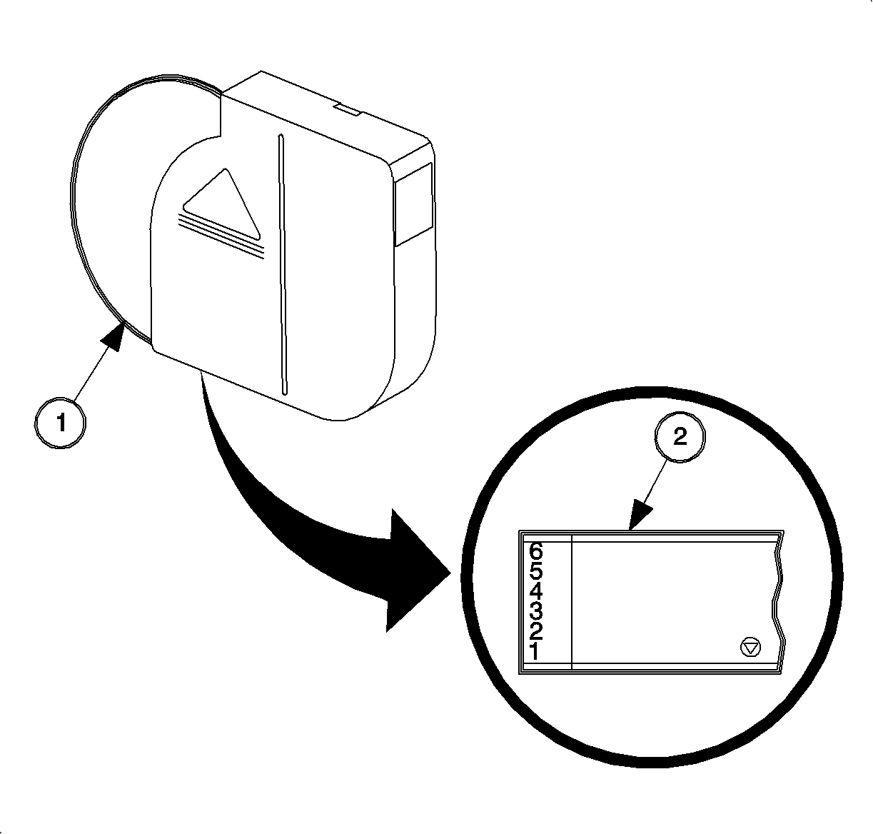
Load up to 6 CDs, label side up (1), in the CD magazine. The order the CDs are
played is from the bottom of the CD magazine to the top (2) (unless in RDM mode).
If you look closely, one of the sides of the magazine shows the numbering of the slots
(1-6).

Important: If all the CDs in the magazine are loaded incorrectly, no CDs will be played.
The CD changer/player will play only those CDs loaded correctly.
| • | Insert one CD in one of the six slots of CD magazine with label-side of
CD facing up. |
| • | CDs can be loaded in any order you wish. |
| • | The label side of the CD must face upward. If a CD is loaded label side
down, the CD changer/player will not be able to recognize the CD. The upside down
CD will be skipped and the next higher available CD will be played. |
| • | Do not touch the recorded surface of a CD when inserting or removing the
CD. |
| • | If the CD has been suddenly moved from cold to warm surroundings, playing
a CD will not be possible until the moisture evaporates. Let the CD changer/player
warm up. |
Removing Compact Discs From CD Magazine

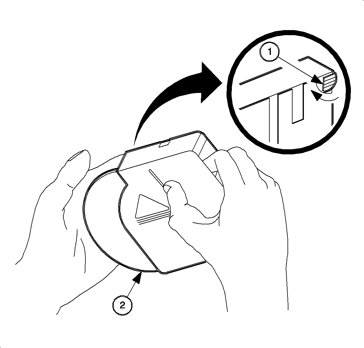
| • | CD magazine release lever (1) |
| • | CD with label side facing upward (2) |
After removing the magazine from the CD changer/player, hold down CD magazine
release lever and pull CD(s) out. The CD magazine release lever is located on the
VERTICAL SIDE of the CD magazine, that the horizontal arrow points to. Do not drop
the CDs.


