Caution: Ensure that the vehicle is properly supported and squarely positioned.
To help avoid personal injury when a vehicle is on a hoist, provide additional support
for the vehicle on the opposite end from which the components are being removed.
- Position the vehicle
on a hoist.
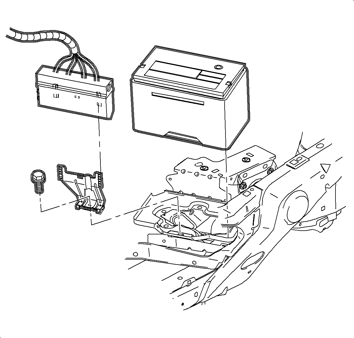
- Remove the battery.
| 2.1. | Disconnect the negative battery cable. |
| 2.2. | Disconnect the positive battery cable. |
| 2.3. | Move the fan control module. Leave the wiring connected, lift the module
up and away from the bracket, and position out of the way. |
| 2.4. | Remove the battery hold-down bracket. |

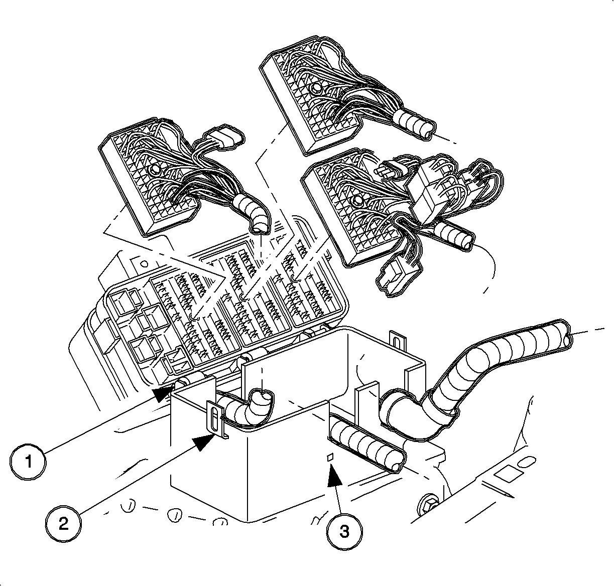
- Disconnect the battery feed to the underhood
fuse block.
- Disconnect the coolant hose from the underhood fuse block.
- Release the retaining tabs on the underhood fuse block cover and remove.
- Release the retaining tabs (2) on the underhood fuse block and
roll the fuse block (1) back to access the electrical connectors.
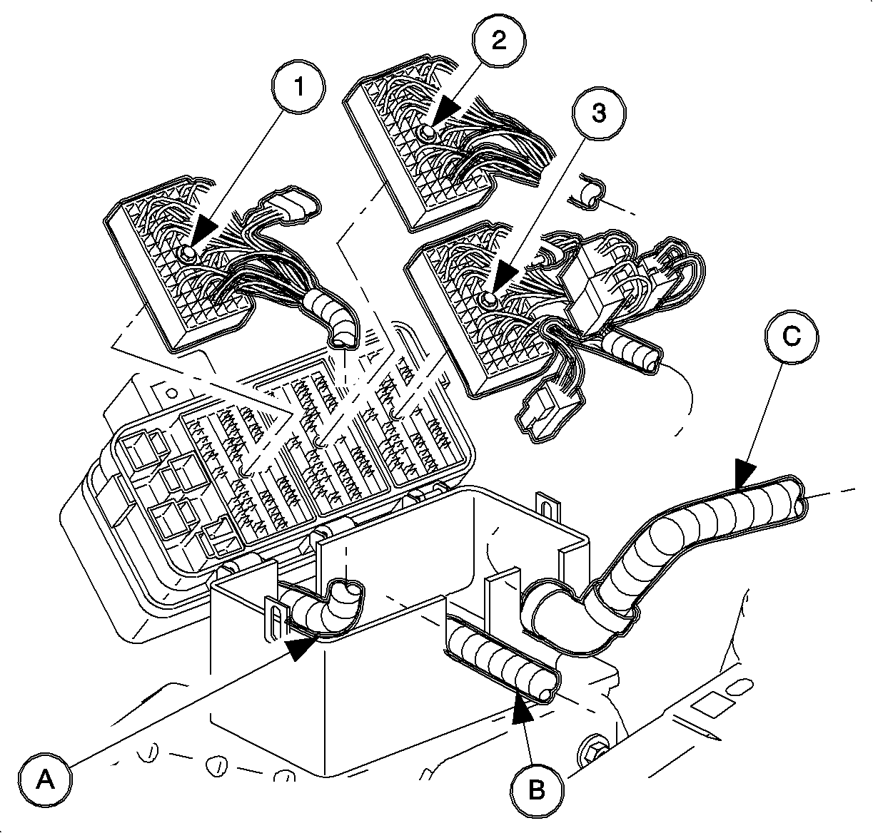
- Remove the following connectors from the underhood
fuse block:
| • | Forward Lamp 68-way (2) |
- Remove the following connectors from the underhood
fuse block.
| • | Forward Lamp 2-way (White) (4) |
- Lift the fuse block off the case.
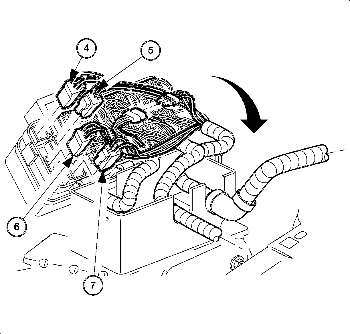
Important: There are 2 tabs that hold the hard shell grommets in place at the bottom
of the grommet. Disengage the tabs to remove the grommet from the case.
- Remove the harnesses from the underhood fuse block case by releasing the retaining
tabs on the bottom of the hard shell grommets.
| • | Instrument Panel (I/P) (C) |
- Remove the underhood fuse block case fastener and the case from the battery
tray.
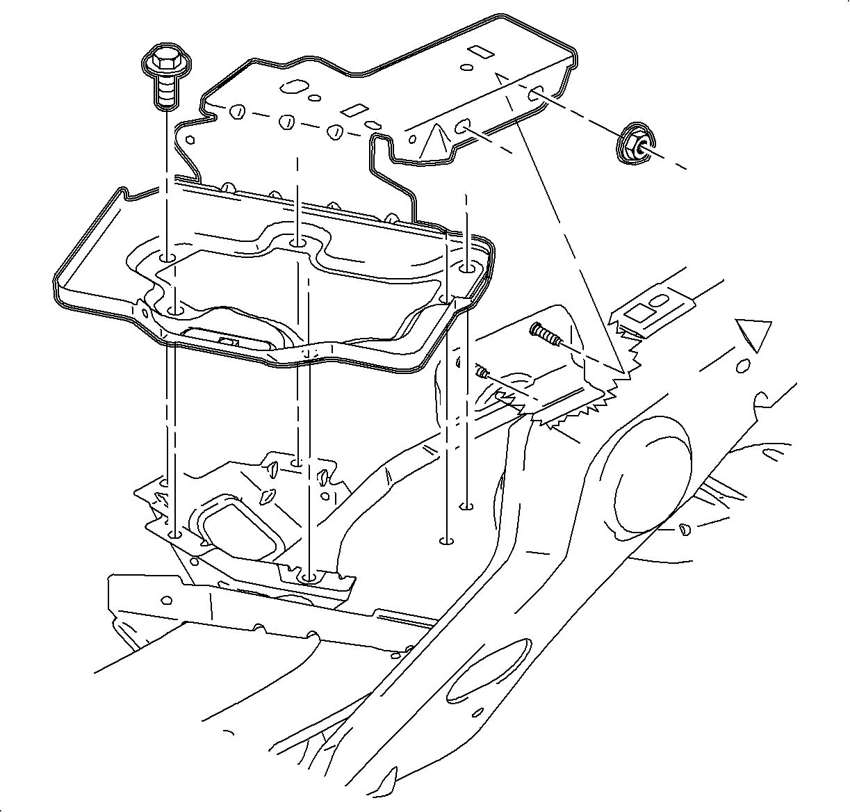
- Remove the battery tray fasteners and the battery
tray.
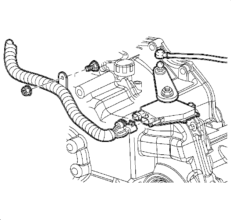
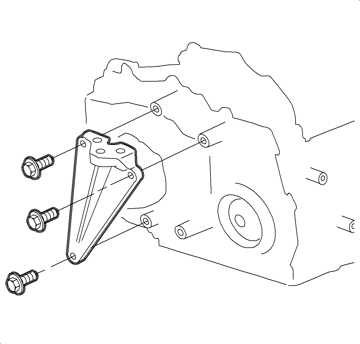
- Remove the wire harness from the transaxle case side cover.
Important: For 4-cylinder vehicles only, perform steps 13-15, if equipped with AIR.
Important: Note the original position of the AIR components.
- Remove the clamp from AIR hose behind the cooling fan.
- Separate the AIR tube from the hose and push the tube back towards the
transaxle.
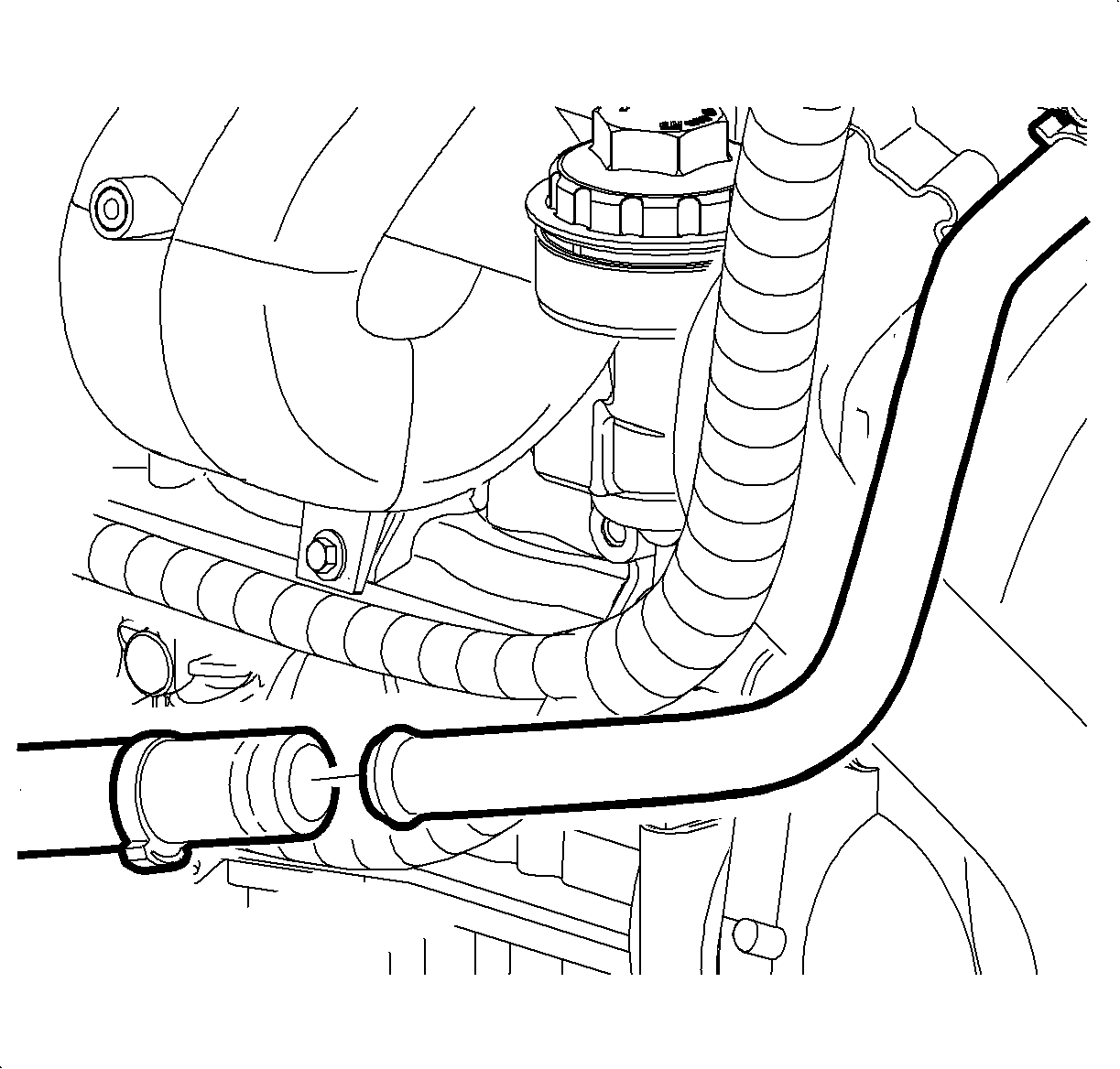
- Remove the hose clip, holding the 2 power
steering lines together.
- Apply the parking brake and place the control
assembly in NEUTRAL. The transaxle manual shaft must be in NEUTRAL position prior
to installing the range switch.
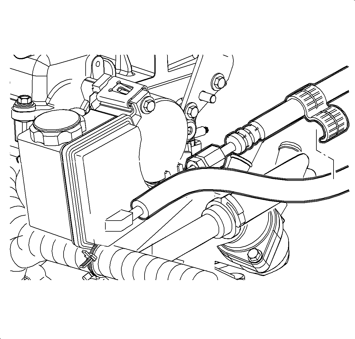
- Remove the shift control cable from the transaxle range switch lever.
- Disconnect the electrical connectors from the transaxle range switch.
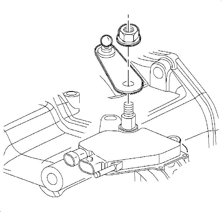
- Remove the transaxle range switch lever nut and
lever.
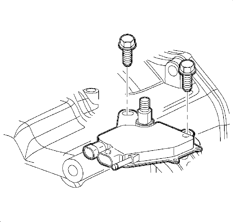
- Remove the transaxle range switch bolts and remove
the switch.
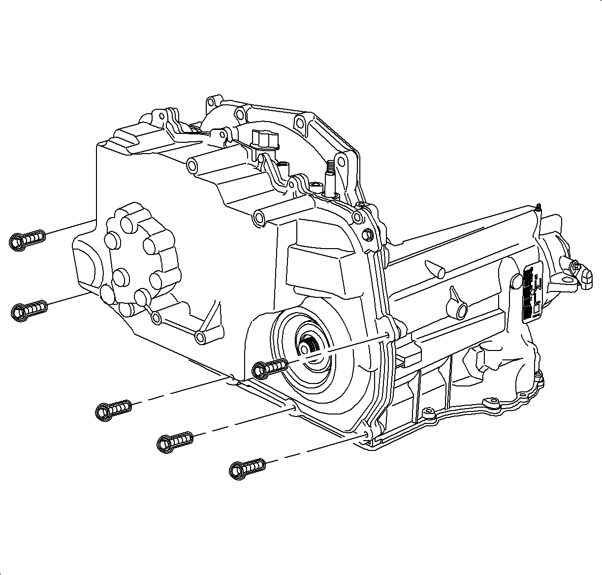
- Remove the upper transaxle case side cover fasteners.
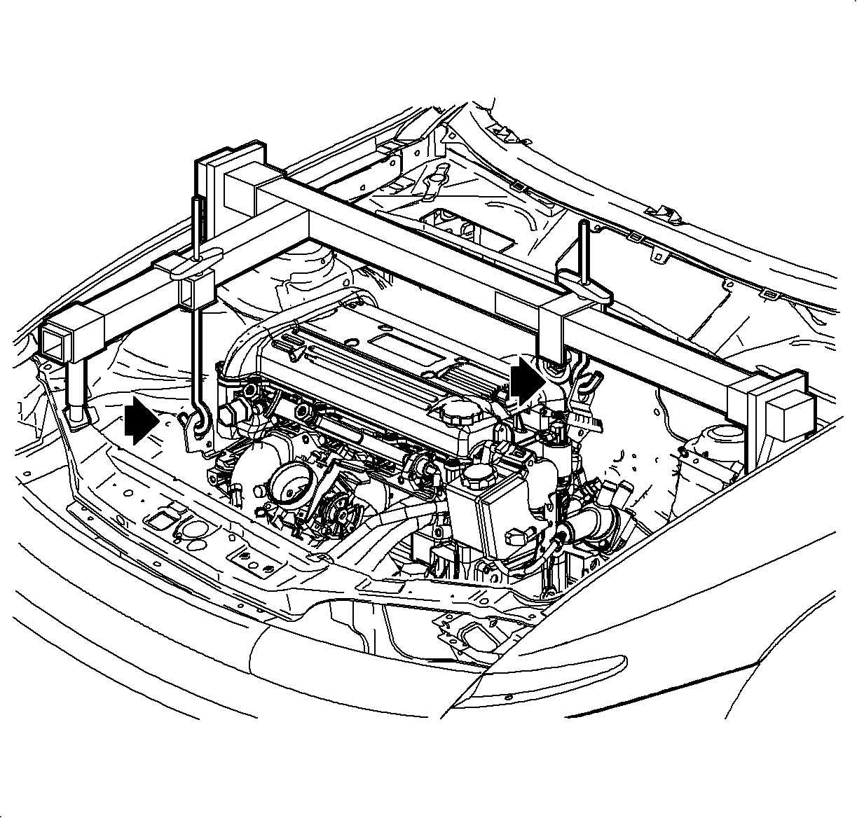
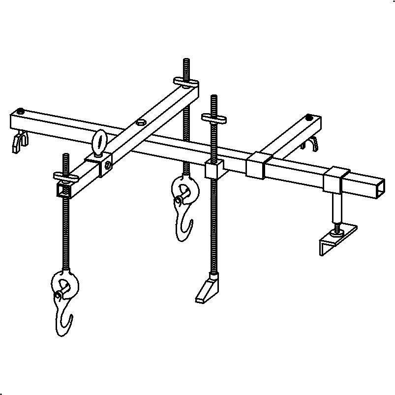
- Install the SA9105E
with the J43405
as shown. L61 (L4) is shown.
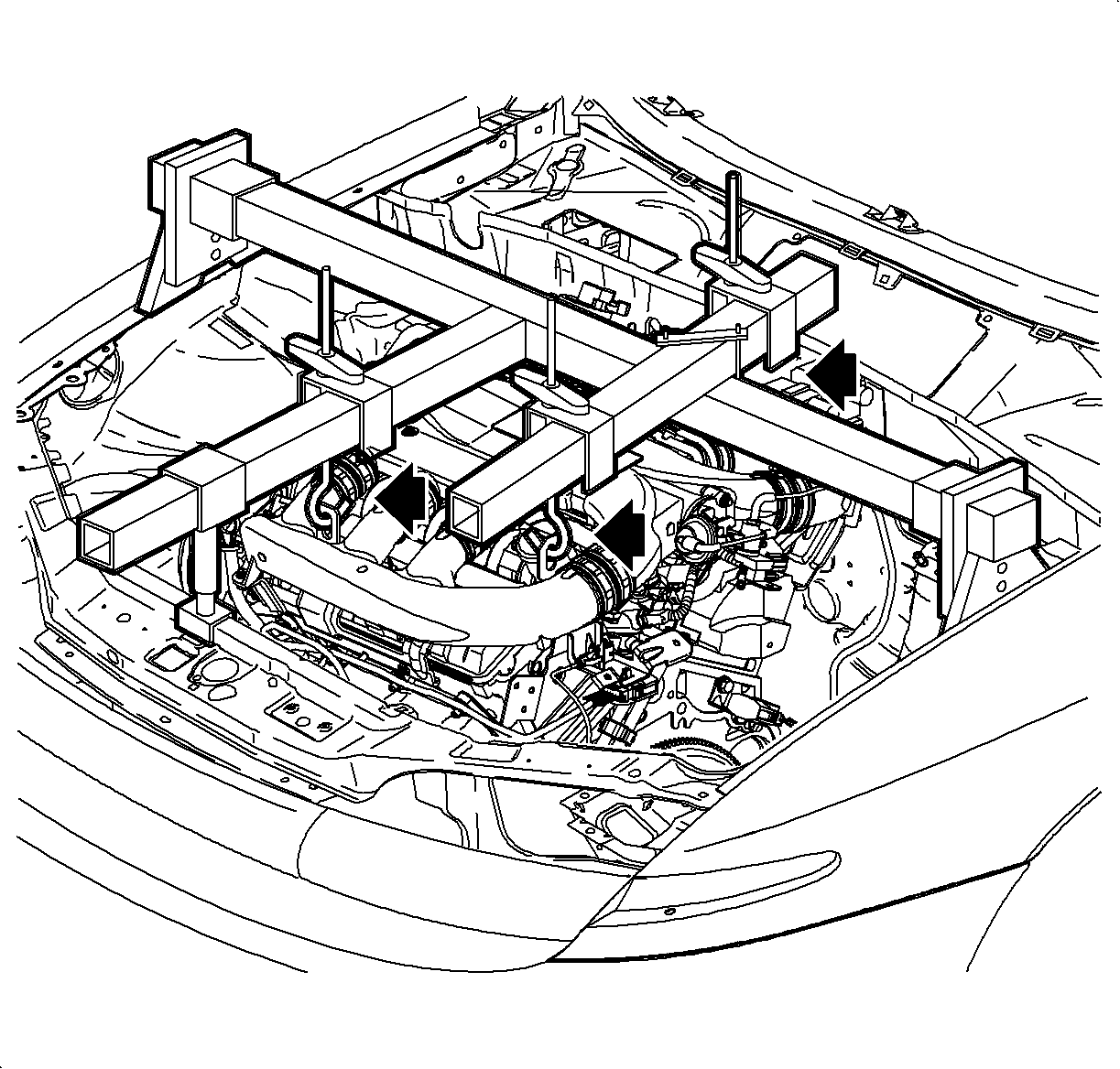
- Install the SA9105E
with the J43405
as shown. L81 (V6) is shown.
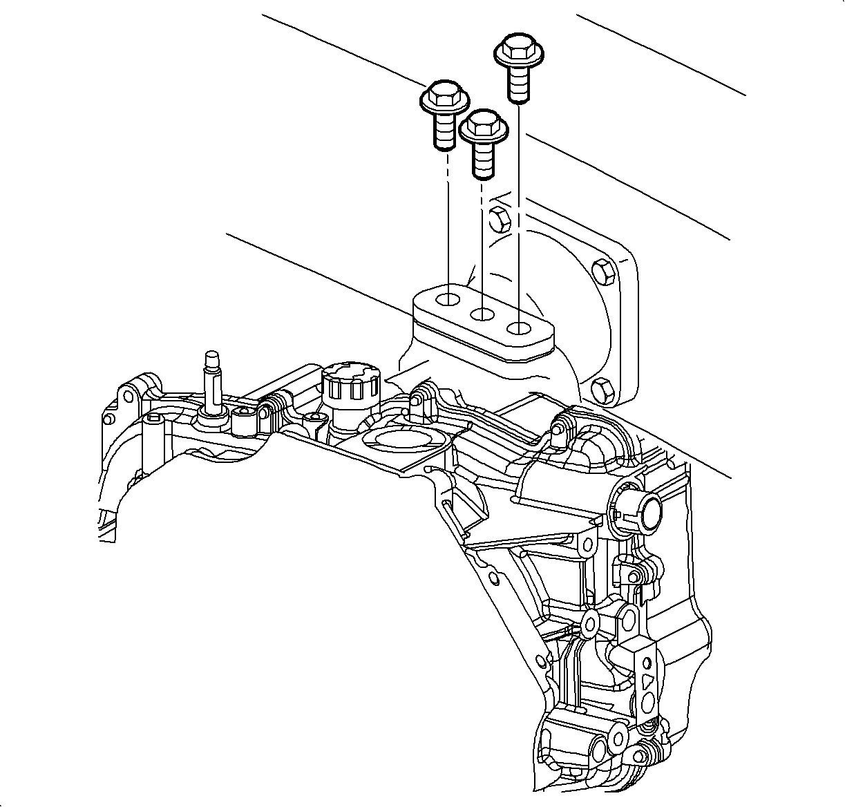
- Mark the position of and remove the left transaxle
mount bolts.
- Remove the left transaxle mount from the engine
compartment rail.
- Remove the frame assembly. Refer to
Frame Replacement
.
Notice: To prevent damage to CV Joint boots, be careful not to allow them to contact
other parts during the removal/installation process. Also, never pull on the shaft
assembly.
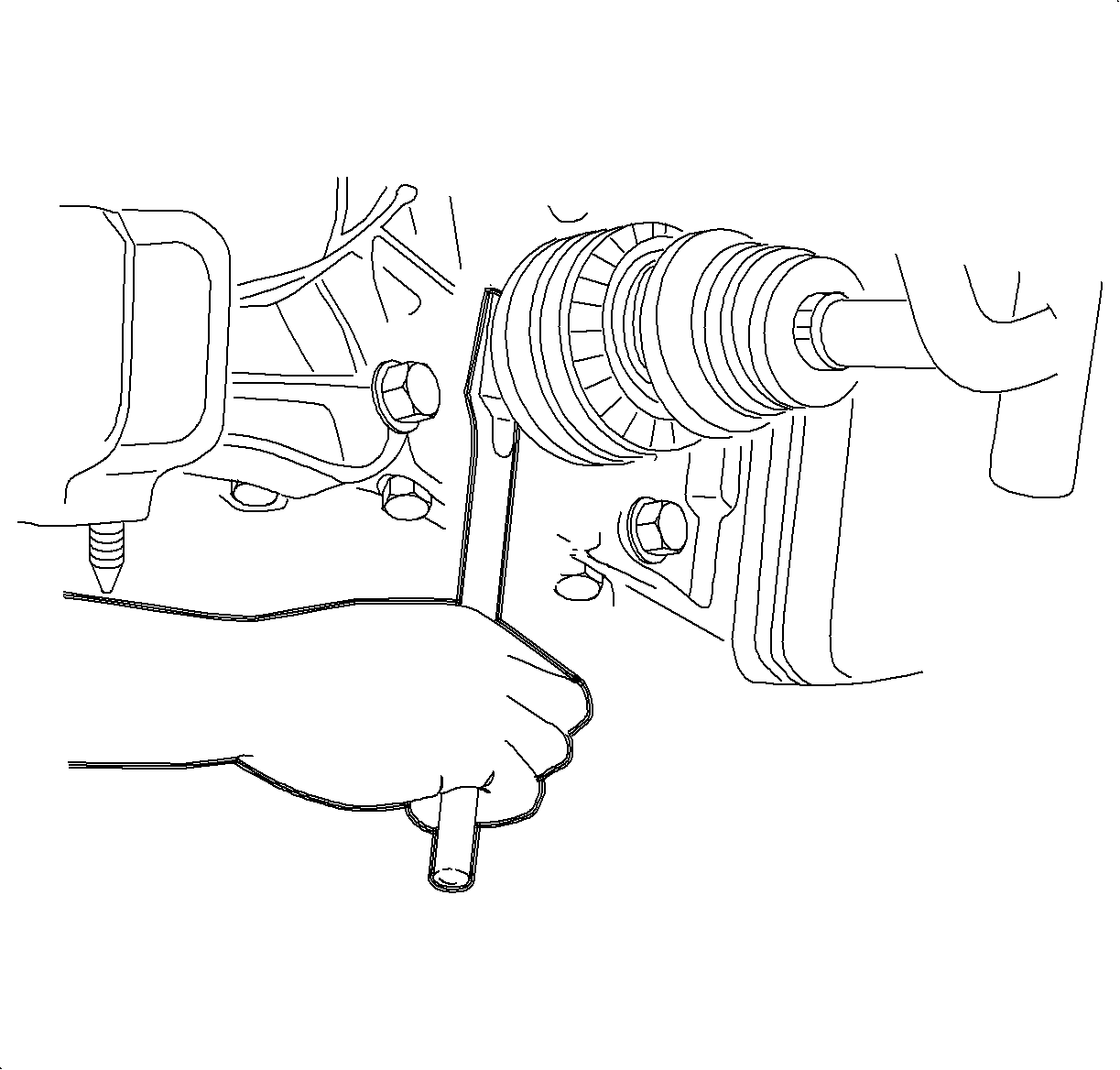
- Remove the left drive
axle from the transaxle using a pry bar. Remove the axle retaining ring from the
output shaft of the transaxle and discard. The axle can be left in the steering
knuckle. Tie the axle up and out of the way.
- Remove the power steering lines from left transaxle
mount bracket. Remove the transaxle mount bracket fasteners and remove the bracket.
Important: Pry on the side cover near locating dowel pins to prevent damage to the sealing
surfaces.
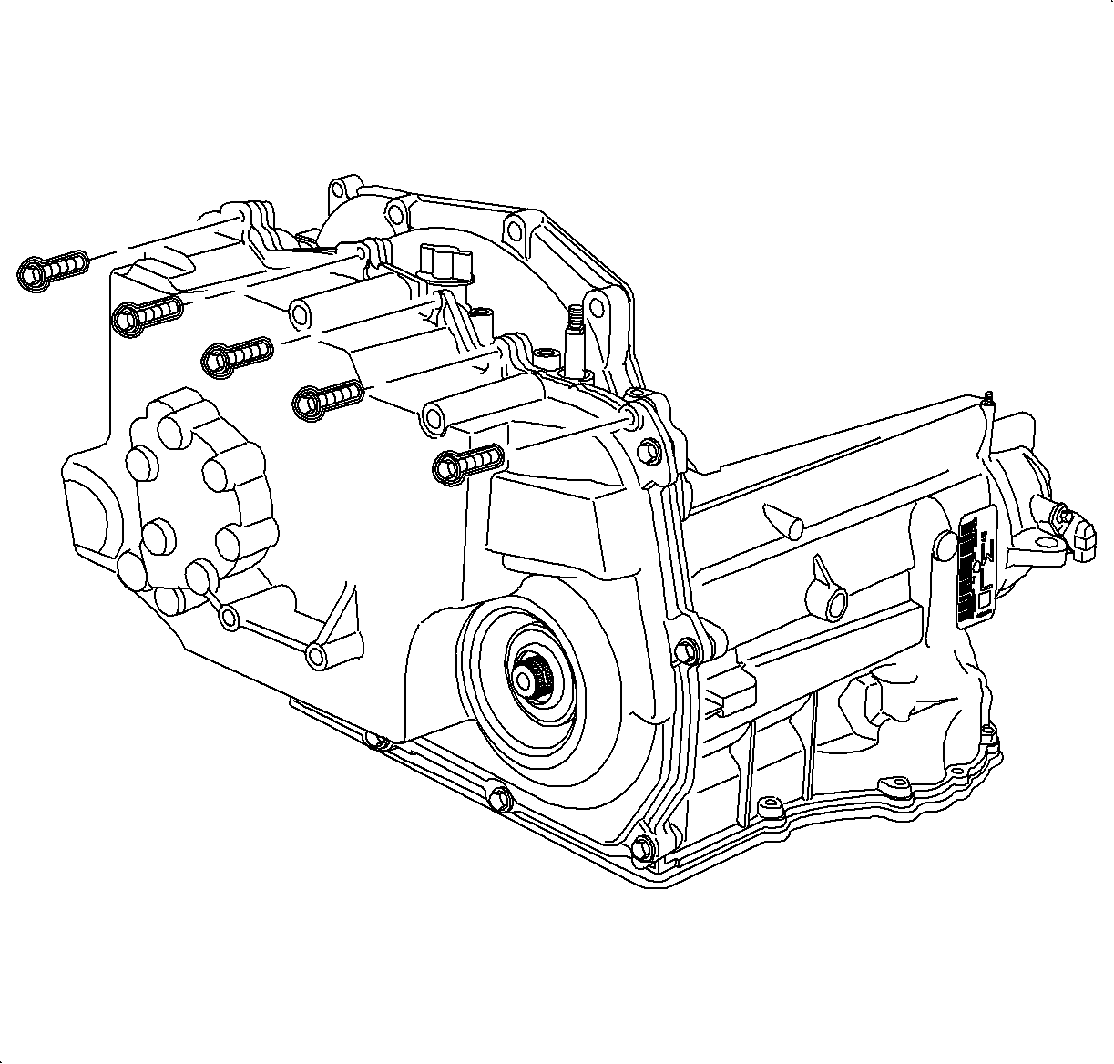
- Remove the remaining transaxle case side cover bolts and remove the case side
cover.
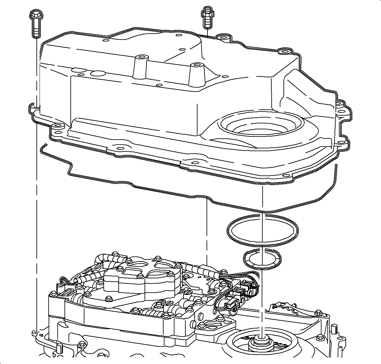
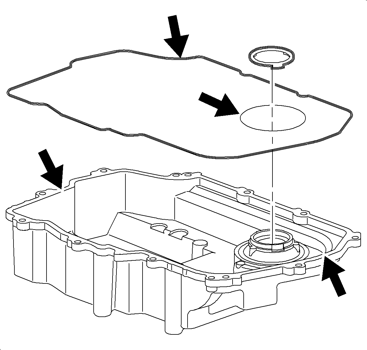
- Remove the 2 case side cover gaskets and side
cover to driven support thrust washer, if they did not remain with the side cover
assembly when it was removed.
- Inspect the case side cover for cracks or damage
to the seal grooves and the mounting bosses.
- Inspect the side cover seals for damage. The side cover seals are reusable
if not damaged.
- Thoroughly clean the side cover and side cover seals. Clean and dry the
seal grooves and axle seal bore.
- Install the case side cover gaskets into grooves on the side cover. Retain
seals with petroleum jelly.
- Install the side cover to driven sprocket thrust washer onto the side
cover. Retain with petroleum jelly.
Notice: J41102 must be used on the output shaft of the transaxle to protect the axle
seal from damage when installing the case side cover. If J41102 is not used, damage
to the seal may result.
- Install the J 41102-1A
on the output shaft of transaxle, and install
the side cover assembly onto the transaxle case.
- Install and hand start the lower side cover-to-transaxle case bolts and
tighten.
Tighten
Tighten the side cover-to-transaxle case bolt to 20 N·m (15 lb ft).
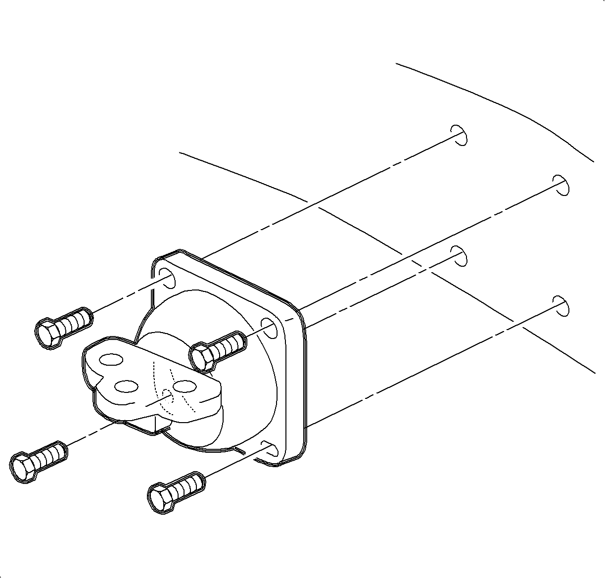
- Install the left transaxle mount bracket to transaxle.
Tighten
Tighten the left transaxle mount bracket-to-transaxle bolts to 90 N·m(66 lb ft).
- Install the power steering lines to the left transaxle mount bracket.
Tighten
Tighten power steering lines-to-left transaxle mount bracket to 10 N·m
(89 lb in).
Notice: In order to prevent damage to shaft splines during vehicle operation, add grease
P/N 7847638 to the splines on the stub shaft.
- Install a new axle retaining clip on the output
shaft of transaxle. Untie the left axle shaft and install the axle shaft into the
transaxle.
- Install the frame assembly. Refer to
Frame Replacement
- Install the left transaxle mount to the engine
compartment rail.
Tighten
Tighten the transaxle mount (left)-to-engine compartment rail bolts to 20 N·m
(15 lb ft).
Notice: If the powertrain mount is not reinstalled in its original position, it could
lead to premature mount wear.
- Reference the alignment
marks made during disassembly and install the left transaxle mount bolts.
Tighten
Tighten the transaxle mount (left)-to-transaxle mount bracket bolts to 55 N·m
(41 lb ft).
- Remove the engine support bar assembly.
- Install the upper transaxle side cover fasteners.
Tighten
Tighten the side cover-to-transaxle case bolts to 20 N·m (15 lb ft).
- Install the wire harness to the transaxle case side cover.
Tighten
Tighten wiring harness attachment fasteners to 20 N·m(15 lb ft).
- Make sure the transaxle manual shaft is in the
NEUTRAL (N) position.
- Align the flats on the transaxle shift shaft with the flats on the transaxle
range switch and install the switch.
- Loosely install the transaxle range switch bolts.
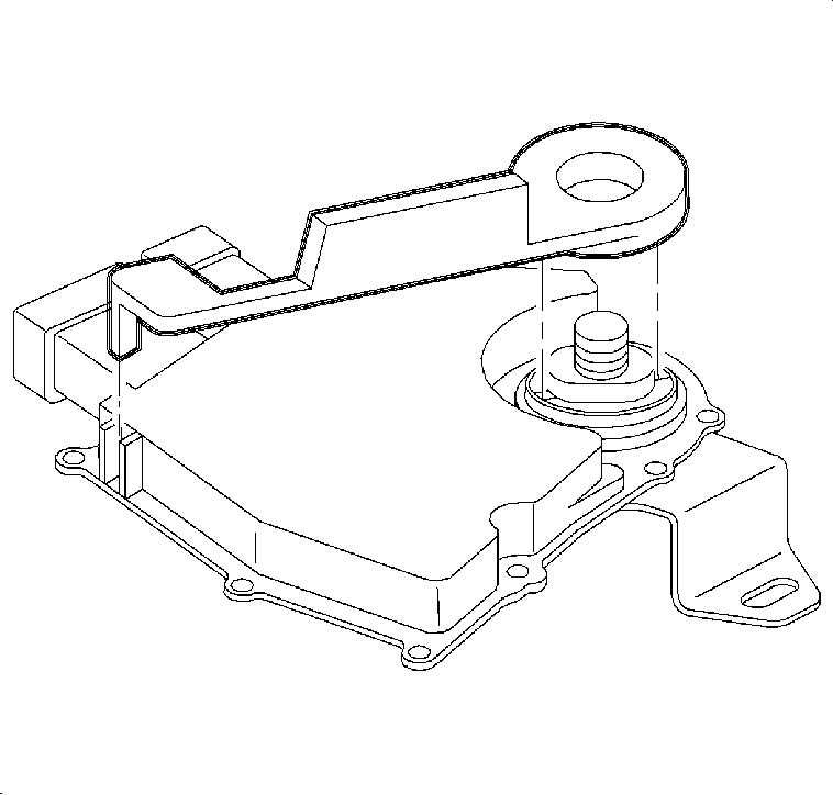
- Insert the J 41545
as shown and rotate the switch until the tool drops into position.
- Tighten the transaxle range switch bolts.
Tighten
Tighten transaxle range switch bolts to 20 N·m (15 lb ft).
- Remove the alignment tool.
- Install the transaxle range switch lever and
nut.
Tighten
Tighten the transaxle range switch lever nut to 35 N·m (26 lb ft).
Important: After adjusting the switch, verify the engine only starts in PARK or NEUTRAL.
If the engine starts in any other position, readjust the switch.
- Connect the transaxle range switch electrical connectors.
- Install the shift control cable to the transaxle range switch lever and
verify proper operation.
Important: For 4-cylinder vehicles only, perform steps 27-30, if equipped with AIR.
- Install the hose clip to the 2 power steering lines.
- Pull the AIR tube back to the original position.
Important: The clamp must be installed with the locking portion facing down.
- Insert the tube into the hose and install the clamp.
Notice: There is a stand-off clip between the AIR tube and the wiring harness at the
front of the transaxle. This must be in place to eliminate the possibility of chafing
between the tube and the harness.
- Ensure the stand-off clip between the AIR
tube and the wiring harness is installed correctly.
- Install the battery tray and the battery tray
fasteners.
Tighten
Tighten the battery bolts to 15 N·m (11 lb ft).
- Install the underhood fuse block case to the
battery tray and install the bolt.
Tighten
Tighten the underhood fuse block case bolt to 9 N·m(80 lb in).
- Install the wire harnesses to the fuse block
case. The wire harness grommets have retaining tabs that lock into the case (3)
when the harnesses are fully installed.
| • | Instrument Panel (I/P) (C) |
- Snap the fuse block onto the fuse block case hinges.
- Install the following connectors to the underhood fuse block:
| • | Forward Lamp 68-way (2) |
- Install the following connectors to the underhood
fuse block:
| • | Forward Lamp 2-way (White) (4) |
- Secure the underhood fuse block to the fuse
block case by rotating down and snapping into place.
- Install the underhood fuse block cover.
- Secure the coolant hose into place on the fuse block cover.
- Install the battery feed cable to the underhood fuse block.
Tighten
Tighten the battery feed cable-to-underhood fuse block bolt to 16 N·m
(12 lb ft).
- Install the battery.
| 40.1. | Install the battery into the battery tray. |
| 40.2. | Install the battery hold-down bracket. |
Tighten
Tighten the battery hold down bracket bolt to 20 N·m(15 lb in).
| | Important: The positive battery terminal must be connected first to prevent arcing.
|
| 40.3. | Install the fan control module by sliding down onto the battery hold-down bracket. |
| 40.4. | Install the positive battery cables first and then the negative battery
cable. |
Tighten
Tighten the battery cables-to-battery to 17 N·m (13 lb ft).
- Start the engine, warm up the transaxle, and check for fluid leaks.
- Check for proper fluid level. Refer to
Transmission Fluid Check
.
