Engine Coolant Fan Replacement Puller Fan - L61
Removal Procedure
- Disconnect the negative battery cable.
- Disconnect the positive battery cable.
- Remove the fan control module by sliding up and off the bracket. Lay the module and wiring out of the way.
- Remove the battery insulating cover.
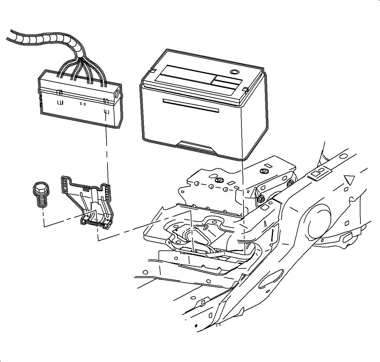
- Remove the battery hold down/fan control module bracket.
- Remove the battery.
- Disconnect both cooling fan electrical connectors.
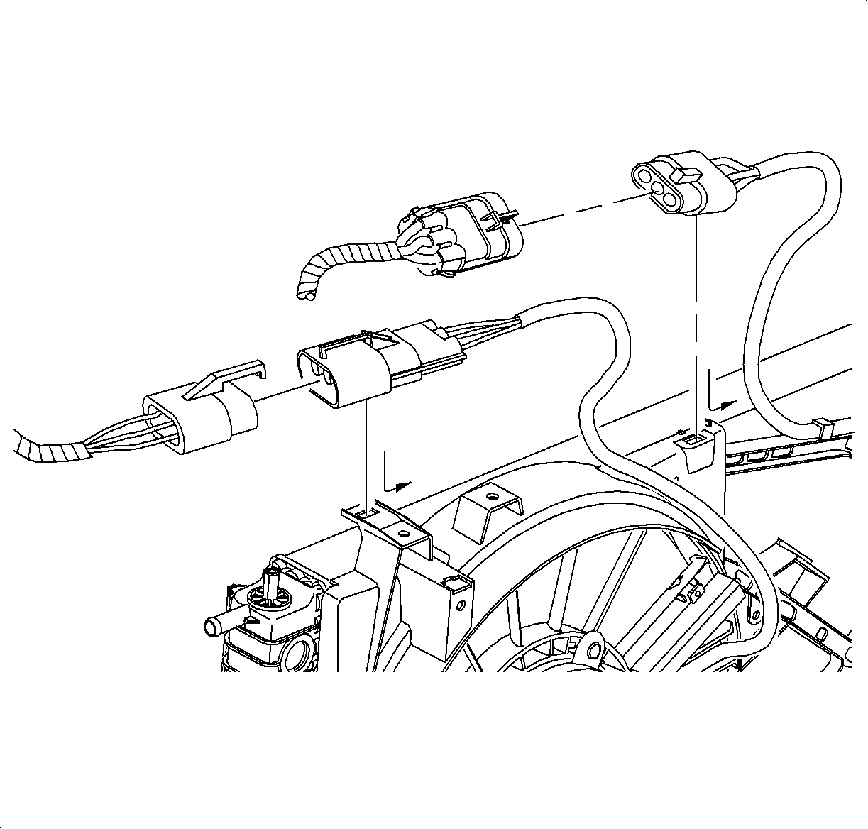
- Remove the electrical connectors from the connector retainer by sliding the connector as shown.
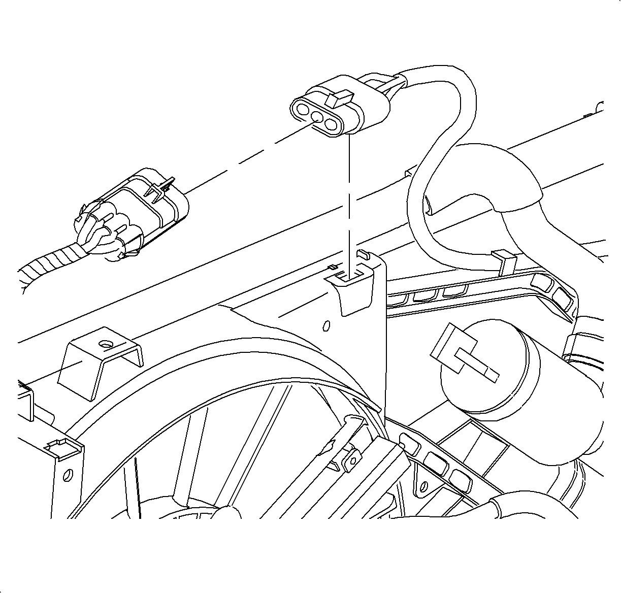
- Remove the pusher fan electrical harness from the fan shroud retainer tabs.
- Remove the wiring harness from the clamp on the fan shroud.
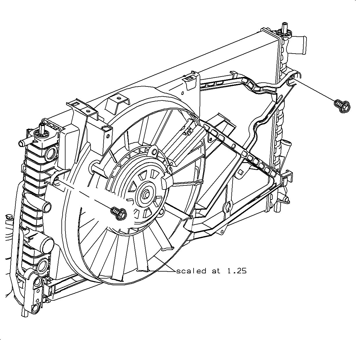
- Remove the fan shroud to radiator bolts.
- Remove the fan and shroud assembly.
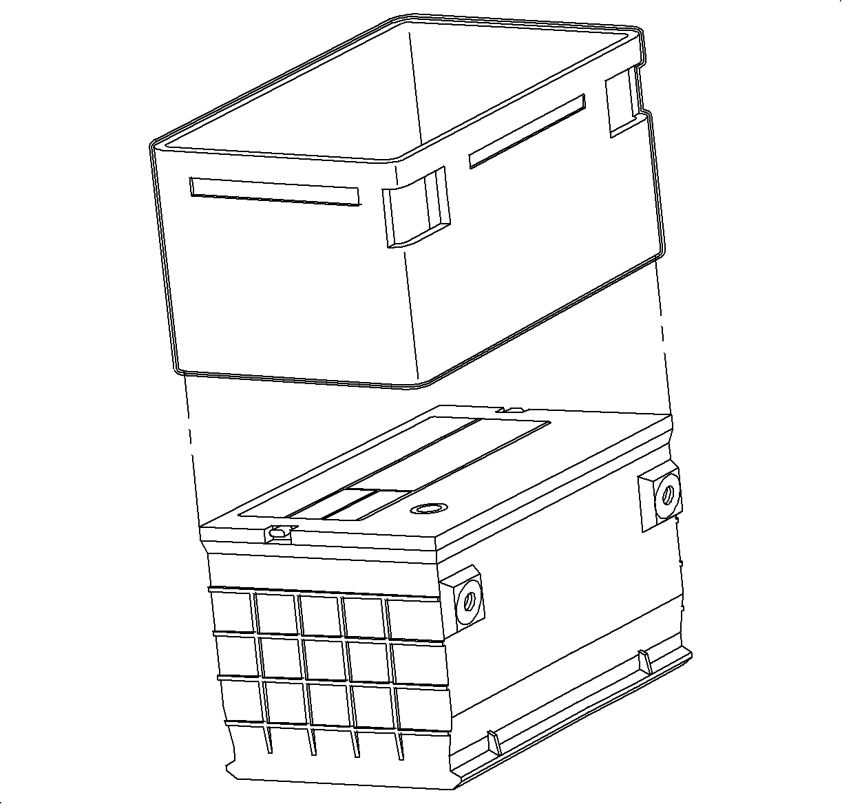
Important: It is not necessary to disconnect the fan control module wiring from the module.
Caution: Refer to Batteries Produce Explosive Gases Caution in the Preface section.
Installation Procedure
- Install the fan and shroud assembly onto the radiator lower tabs.
- Install the fan shroud to the radiator bolts.
- Route the pusher fan electrical harness around the outside of the radiator end tank to the upper fan shroud.
- Install the fan electrical connectors into the connector retainers as shown.
- Connect both fan electrical connectors.
- Install the wiring harness into the clamp on the fan shroud.
- Install the pusher fan harness into the routing tabs on the fan shroud.
- Verify the battery tray is clean.
- Install the battery.
- Install the battery hold down/fan control module bracket.
- Install the battery insulating cover.
- Install the fan control module by sliding down onto the bracket.
- Connect the positive battery cable.
- Connect the negative battery cable.
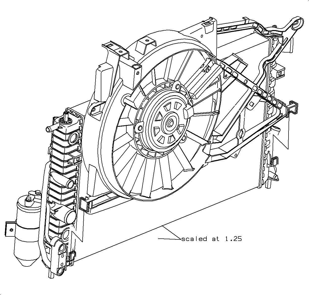
Important: Verify that the pusher fan electrical harness is not between the fan shroud and the radiator.

Tighten
Tighten the puller fan shroud-to-radiator bolts to 4 N·m (35 lb in).

Tighten
Tighten the battery hold down bracket bolts to 20 N·m (15 lb ft).
Important: Battery life is reduced if a battery insulation cover is not used.
Tighten
Tighten the battery terminal bolts to 17 N·m (13 lb ft).
Tighten
Tighten the battery terminal bolts to 17 N·m (13 lb ft).
Engine Coolant Fan Replacement Puller Fan - L81
Removal Procedure
- Disconnect the negative battery cable.
- Disconnect the positive battery cable.
- Remove the fan control module by sliding up and off the bracket. Lay the module and wiring out of the way.
- Remove the battery insulating cover.
- Remove the battery hold down fan control module bracket.
- Remove the battery.
- Drain the coolant. Refer to Draining Coolant .
- Remove the power steering fluid reservoir to the fan shroud bolts and position the reservoir rearward in the car.
- Disconnect both cooling fan electrical connectors.
- Remove the electrical connectors from the connector retainer by sliding the connector as shown.
- Remove the pusher fan electrical harness from the fan shroud retainer tabs.
- Remove the upper transaxle cooler line from the radiator end tank and unsnap from the end tank retainer.
- Cap or tape off the transaxle oil cooler line to prevent oil loss or contamination.
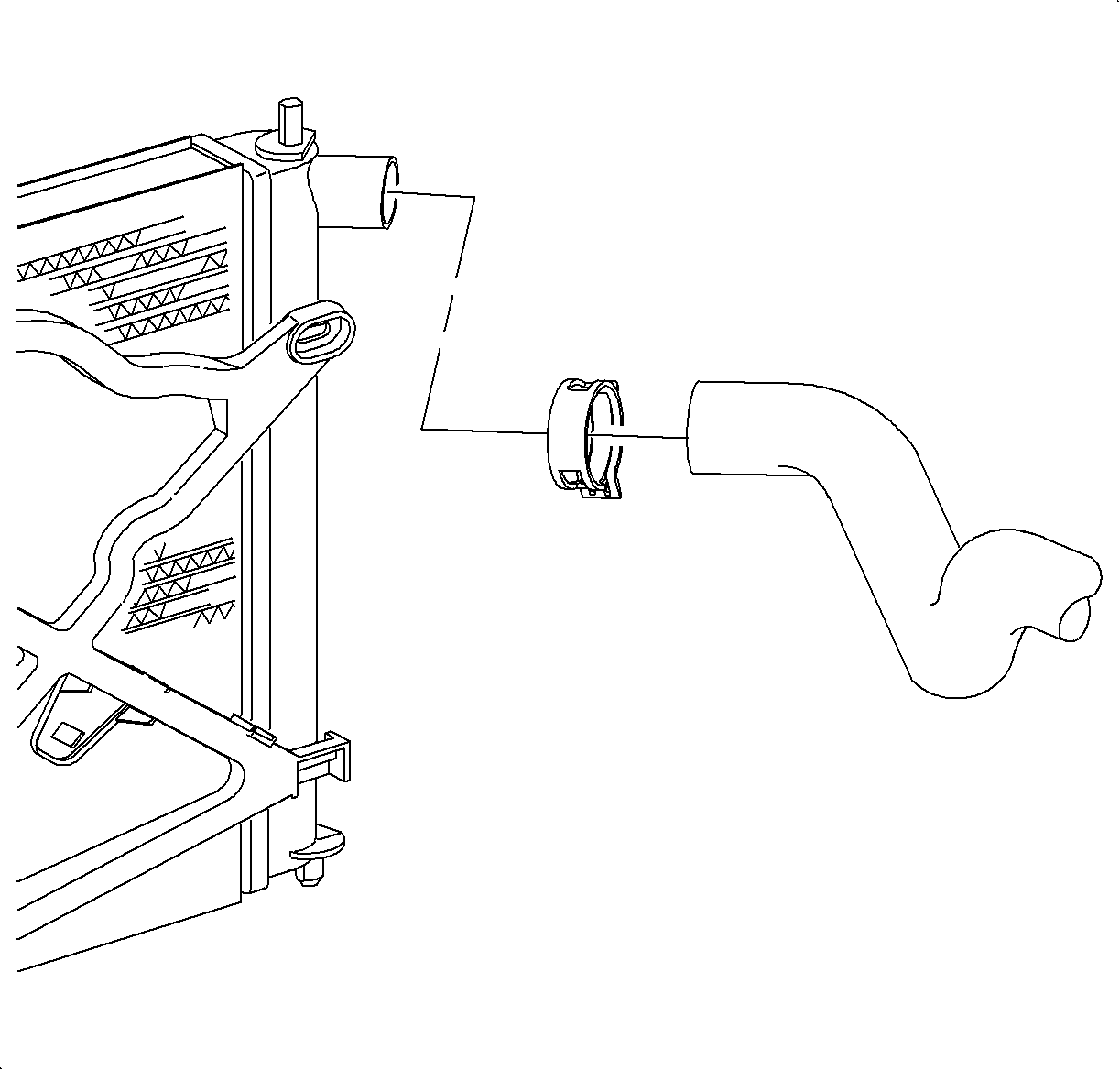
- Remove the upper radiator hose to radiator clamp and remove the hose from the radiator end tank.
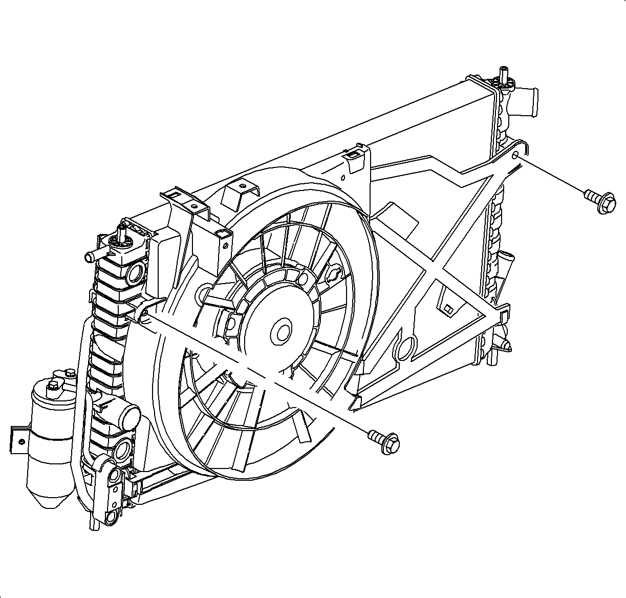
- Remove the fan shroud to radiator bolts and remove.

Important: It is not necessary to disconnect the fan control module wiring from the module.

Caution: Do not tip the battery over a 45 degree angle or acid could spill causing serious personal injury.


Installation Procedure
- Install the fan and shroud assembly onto the radiator lower tabs.
- Install the fan shroud to radiator bolts.
- Install the upper transaxle oil cooler line into the radiator end tank retainer.
- Remove the cap and install the upper transaxle oil cooler line to the radiator end tank.
- Route the pusher fan electrical harness around the outside of the radiator end tank to upper fan shroud.
- Install the fan electrical connectors into the connector retainers as shown.
- Connect both fan electrical connectors.
- Install the pusher fan harness under the routing tabs on the fan shroud.
- Install the upper radiator hose to the radiator end tank and position the clamp at the 12 o'clock position.
- Install the power steering fluid reservoir to the fan shroud bolts.
- Verify the battery tray is clean.
- Install the battery.
- Install the battery hold down/fan control module bracket.
- Install the battery insulating cover.
- Install the fan control module by sliding down onto the bracket.
- Connect the positive battery cable.
- Connect the negative battery cable.
- Fill the cooling system. Refer to Coolant Replacement .
- Use fresh water to rinse away any coolant that was spilled during the service.

Important: Verify that the pusher fan electrical harness is not between the fan shroud and the radiator.

Tighten
Tighten the fan shroud-to-radiator bolts to 4 N·m (35 lb in).

Tighten
Tighten the upper transaxle cooler line-to-radiator end tank to 25 N·m
(18 lb ft).


Tighten
Tighten the power steering fluid reservoir to fan shroud bolts to 5 N·m
(44 lb in).

Tighten
Tighten the battery hold down bracket to 20 N·m (15 lb ft).

Notice: Battery life is reduced if a battery insulation cover is not used.
Tighten
Tighten the battery terminal bolts to 17 N·m (13 lb ft).
Tighten
Tighten the battery terminal bolts to 17 N·m (13 lb ft).
Engine Coolant Fan Replacement Pusher Fan
Removal Procedure
- Disconnect the negative battery cable.
- Disconnect the pusher fan electrical connector.
- Remove the pusher fan harness from the puller fan shroud tabs and push the harness clear of the radiator end tank.
- Raise the vehicle.
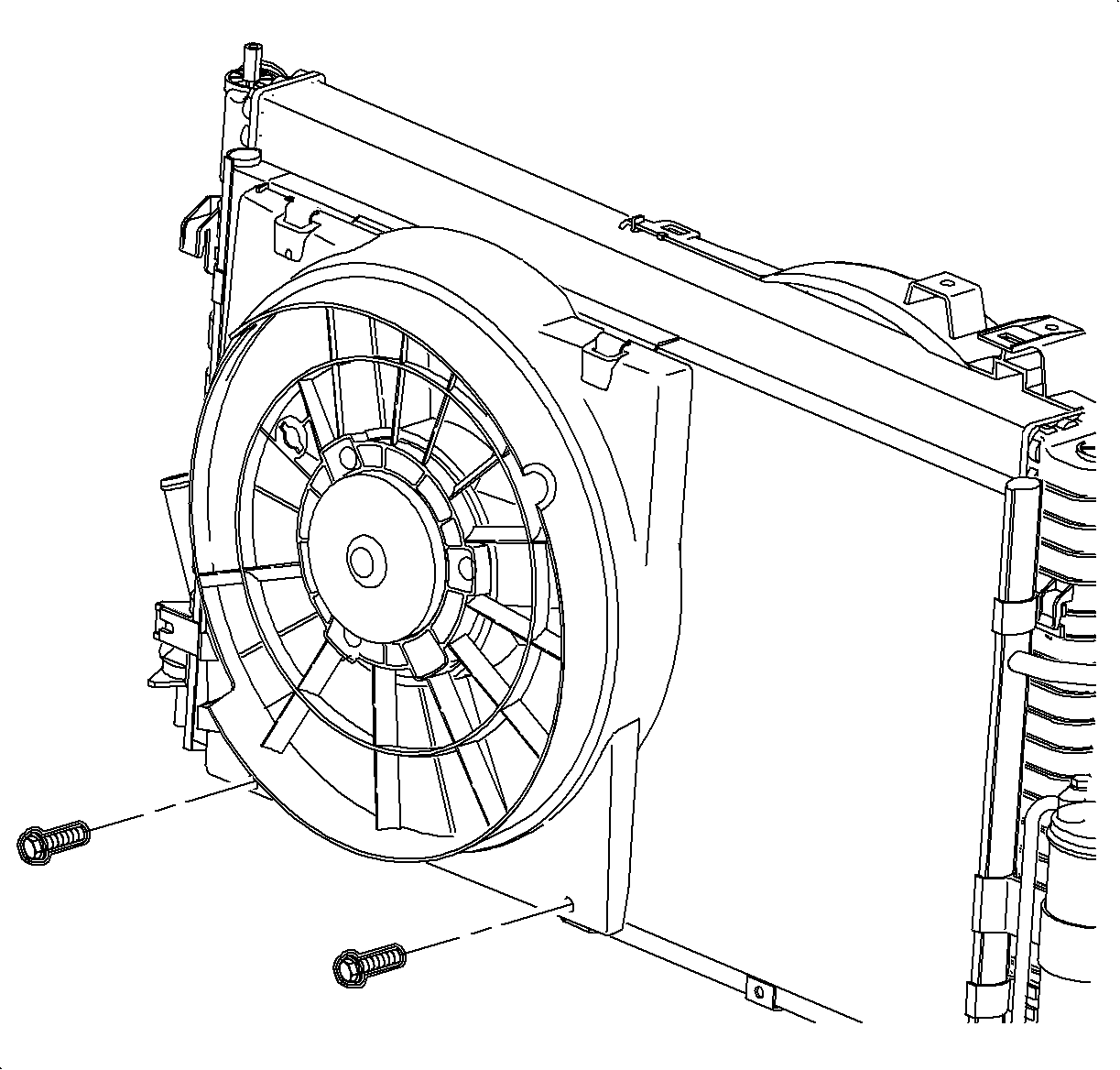
- Remove the pusher fan to condenser retaining bolts.
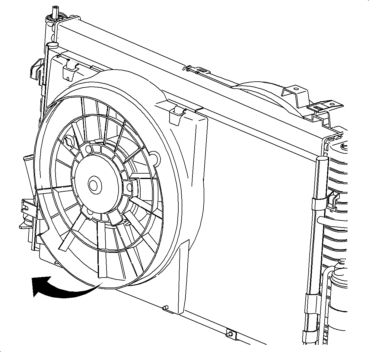
- Pull the lower fan shroud forward and then down to remove.
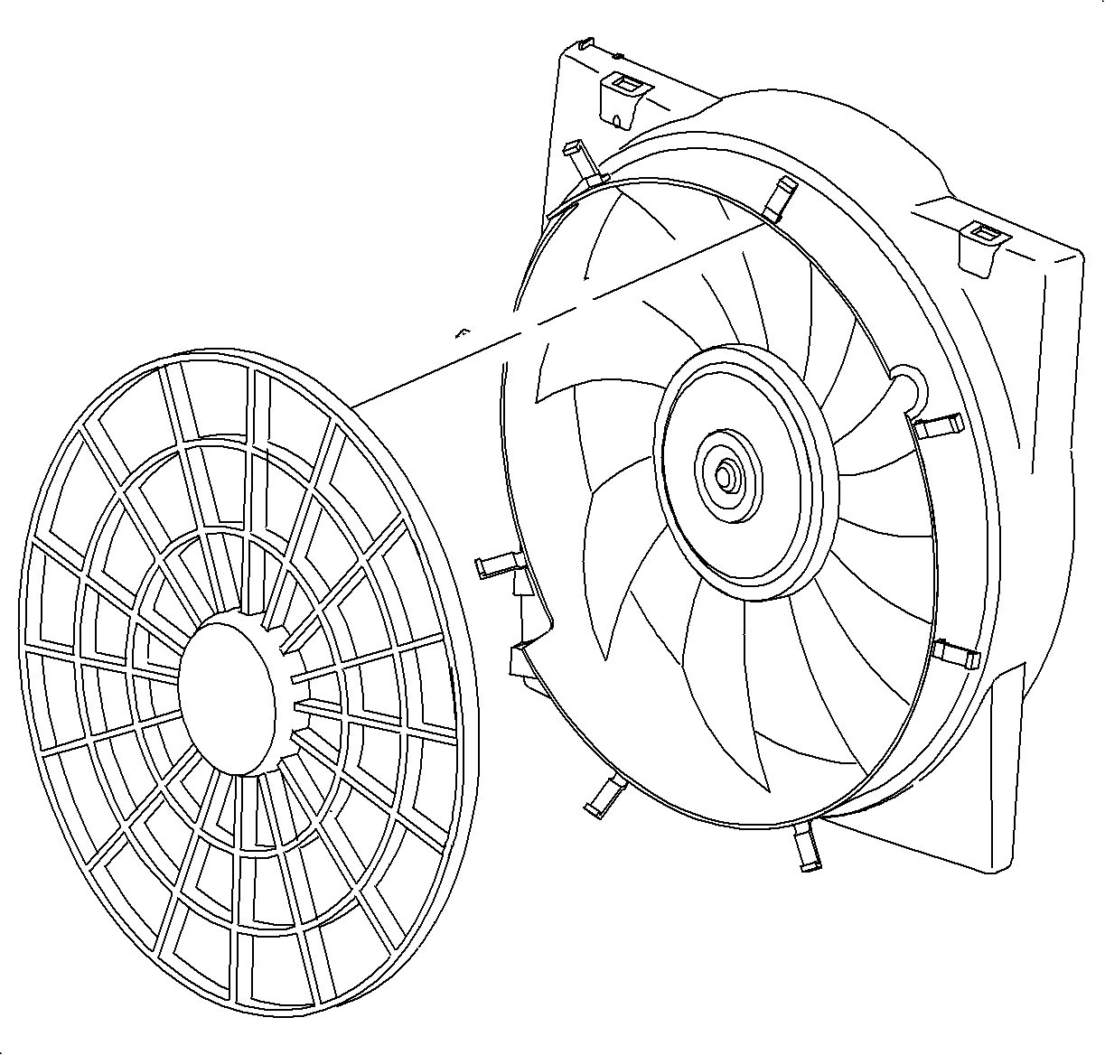
- If the pusher fan is being replaced, remove the finger guard by depressing the tabs at the 4 locations.

Caution: Refer to Vehicle Lifting Caution in the Preface section.
Installation Procedure
- If the pusher fan is being replaced, snap the finger guard onto the new pusher fan.
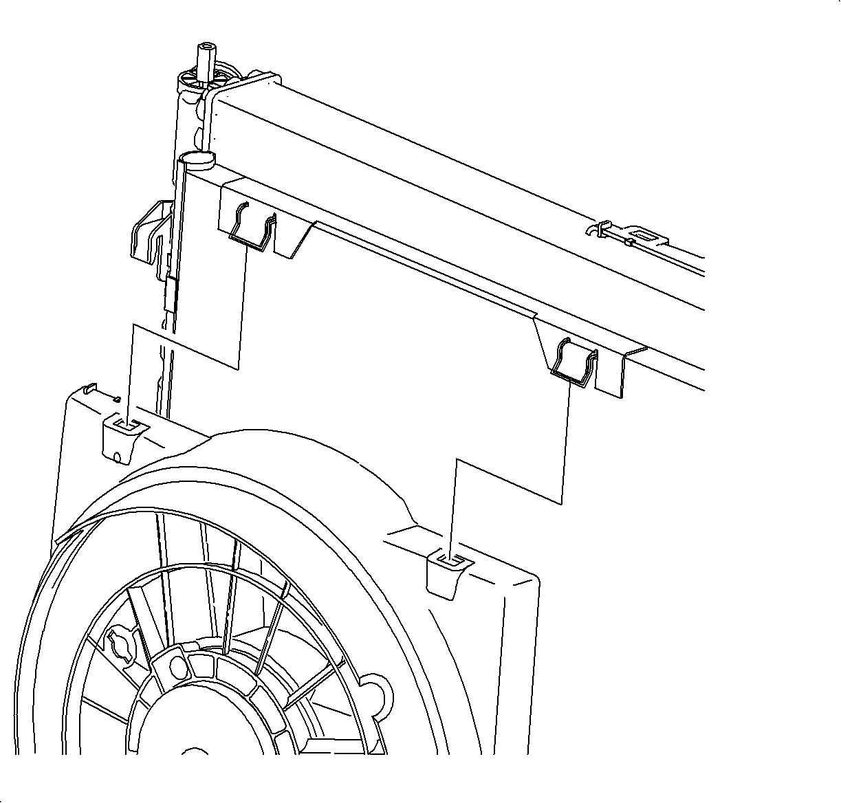
- Slide the upper pusher fan shroud under the retaining tabs located at the upper edge of the condenser.
- Rotate the lower fan shroud onto the condenser and install the retaining bolts.
- Route the pusher fan electrical harness around the outside of the radiator end tank, below the upper radiator hose.
- Lower the vehicle.
- Install the pusher fan harness into the mounting tabs on the puller fan shroud.
- Connect the pusher fan electrical connector.
- Connect the negative battery cable.

Notice: Position pusher fan electrical harness in shroud indentation to prevent harness damage.

Tighten
Tighten the lower fan shroud-to-condenser bolts to 4 N·m (35 lb in).

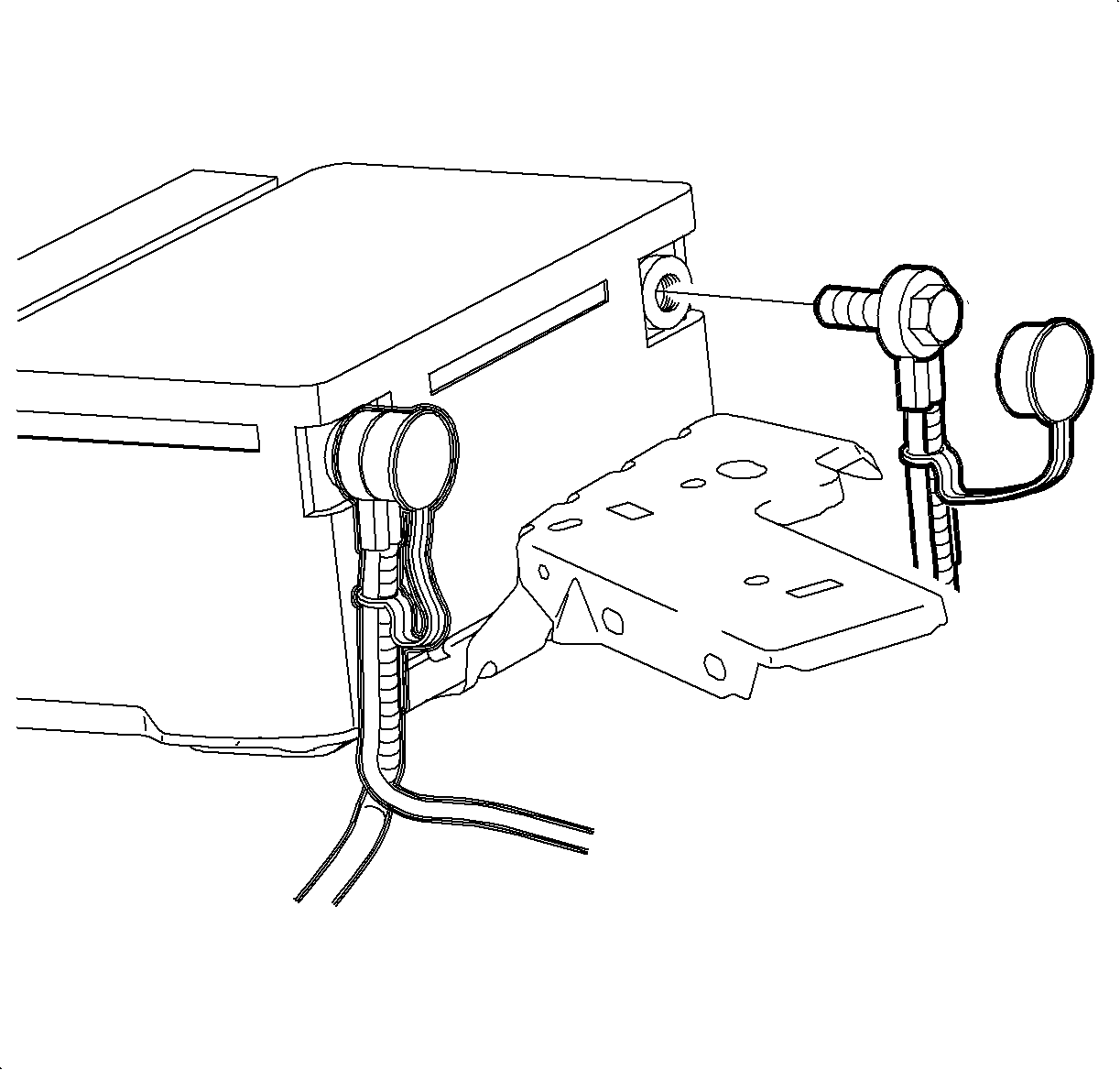
Tighten
Tighten the battery terminal bolts to 17 N·m (13 lb ft).
