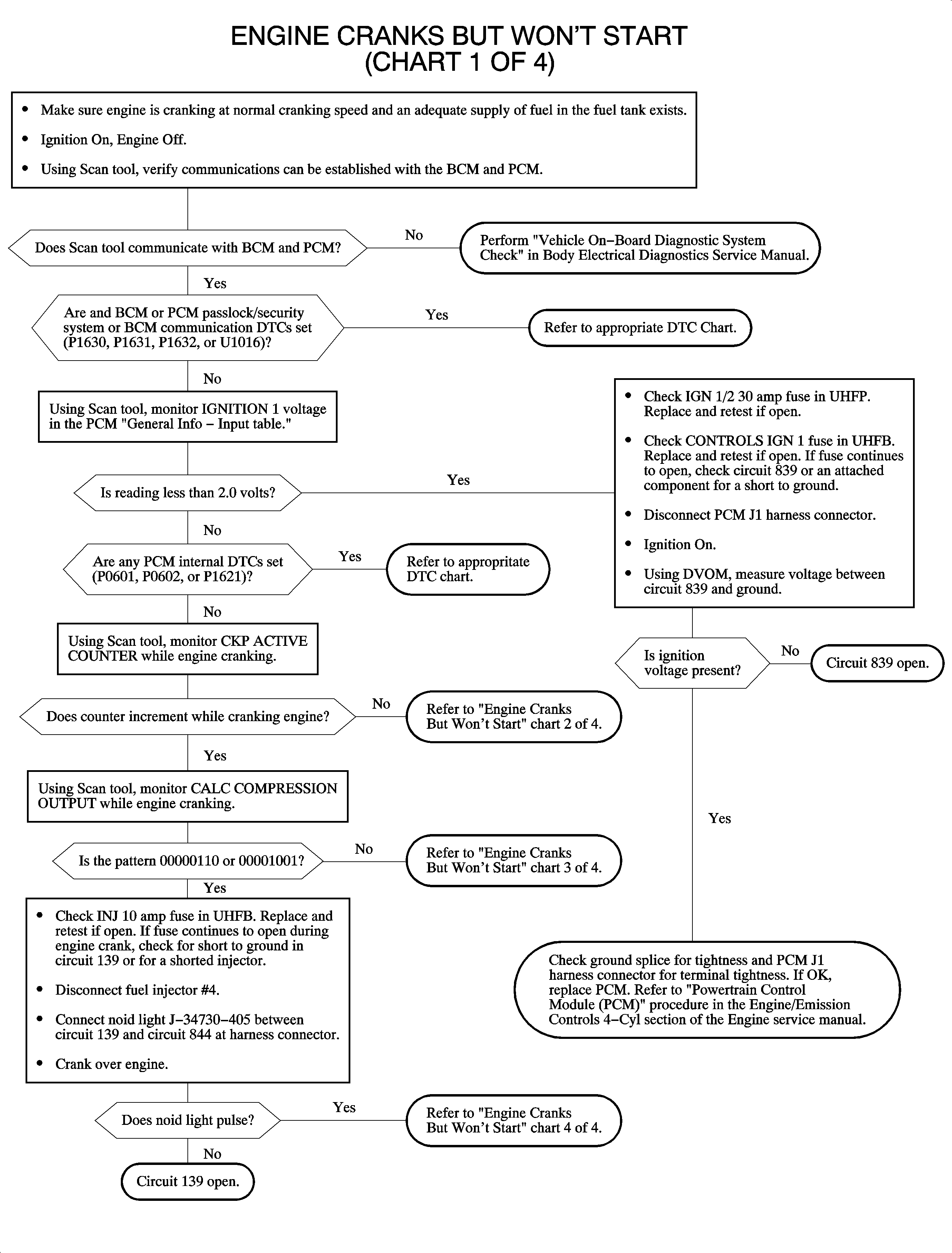
Engine Cranks But Will Not Start (Chart 1 or 4)
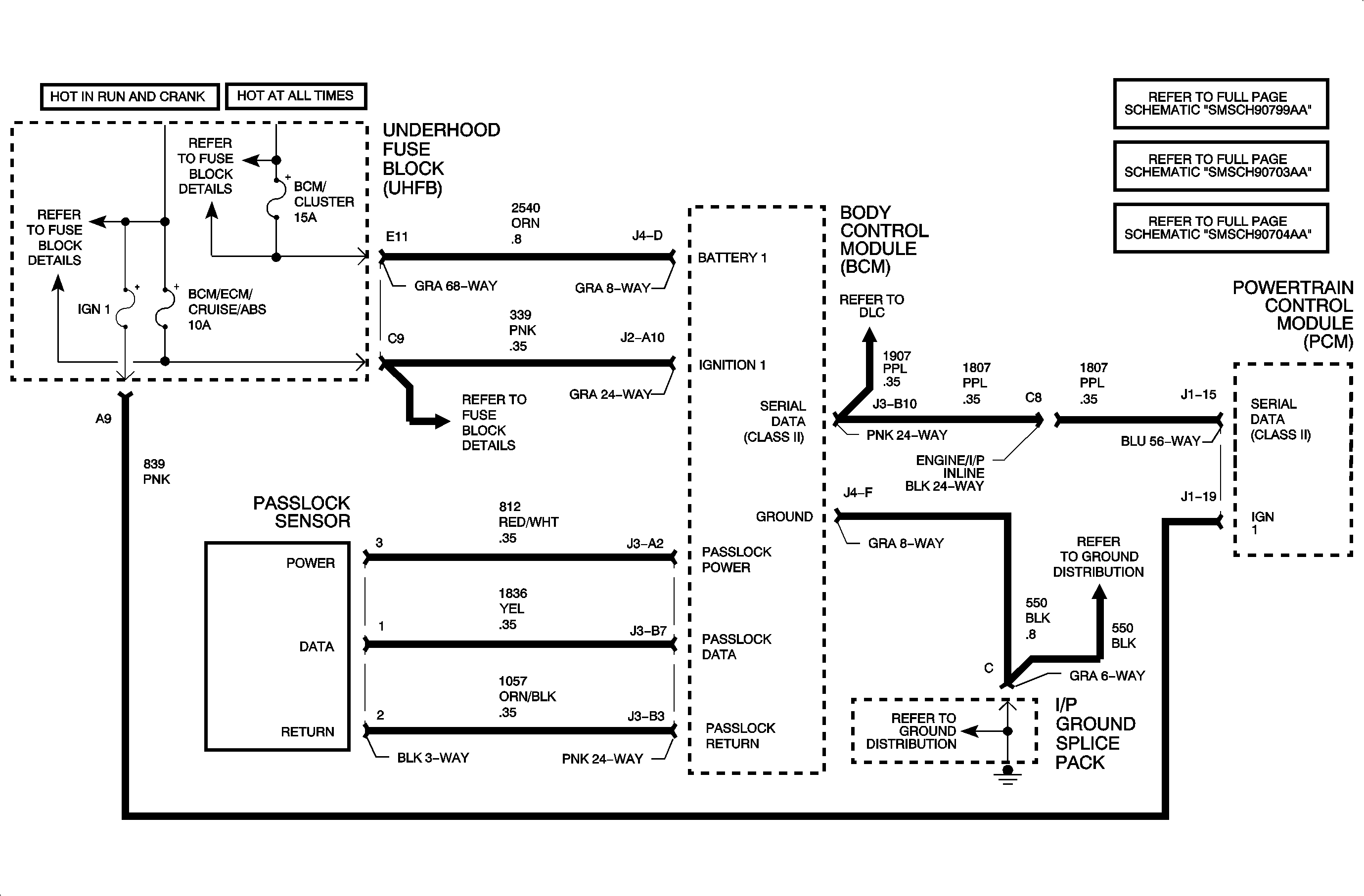
In order to correctly diagnose a no start condition, battery voltage must be above 11 volts and the engine must be cranking at normal cranking speed (above 200 RPM). Fuel level and fuel quality in the fuel tank should be checked. Do not solely rely on the fuel gage for the level reading. When the engine is cranked, the BCM will check the password from the Passlock sensor. If the password is not received within a certain amount of time or does the match the BCM password, the BCM will send a fuel disable password to the PCM over the Class II link. The SECURITY telltale will flash and the engine will not be allowed to start. If the passwords match, the BCM will send the password over the Class II link to the PCM. If the PCM password does not match the BCM password, or if the PCM does not receive a password from the BCM, it will allow the engine to start then stall within 4 seconds. The SECURITY telltale will flash for 10 minutes if the PCM receives no password, an incorrect password, or a disable fuel command. If the password to the PCM is correct, the engine will operate normally. The password is sent continuously by the BCM to the PCM during run mode. If the password becomes lost or incorrect during the drive cycle, the vehicle will be allowed to start on succeeding ignition cycles without the aid of Passlock and the SECURITY telltale will be ON steady. This mode is called fail enable mode.
Diagnostic Aids
DTCs that may cause a no start and should be diagnosed first:
| • | U-type communication DTC U1000, U1016, or U1064 |
| • | BCM or PCM Passlock/security system DTC P1630, P1631, P1632, or B1372 |
| • | PCM internal fault DTC P0601, P0602, or P1621 |
Make sure ECT, MAP, and TP sensor readings on the scan tool with the ignition ON and the engine OFF look normal. The MAP should be between 98-104 kPa (14-15 psi) with the ignition ON and the engine OFF. The ECT and IAT should be within 4°C (10°F) of each other if the vehicle has been sitting overnight. A skewed sensor reading may cause a hard/no start condition.
If no RPM from the crankshaft position (CKP) sensor is detected, spark and fuel will not be turned ON. The signal from the CKP sensor is sent to the PCM. When the engine is cranking, the scan tool CKP ACTIVE COUNTER should continuously count up to 255 then reset to 0.
Check for a flooded engine.
These PCM fuses in the UHFB will cause a no start if open:
| • | CONTROLS IGN 1 10 amp |
| • | EIS 10 amp |
| • | FUEL PUMP 15 amp |
| • | IGN 1/2 30 amp |
| • | INJECTOR 10 amp |
These BCM fuses in the UHFB will cause a start then stall condition within 4 seconds if open:
| • | BCM/CLUSTER 15 amp |
| • | BCM/ECM/CRUISE/ABS 10 amp |
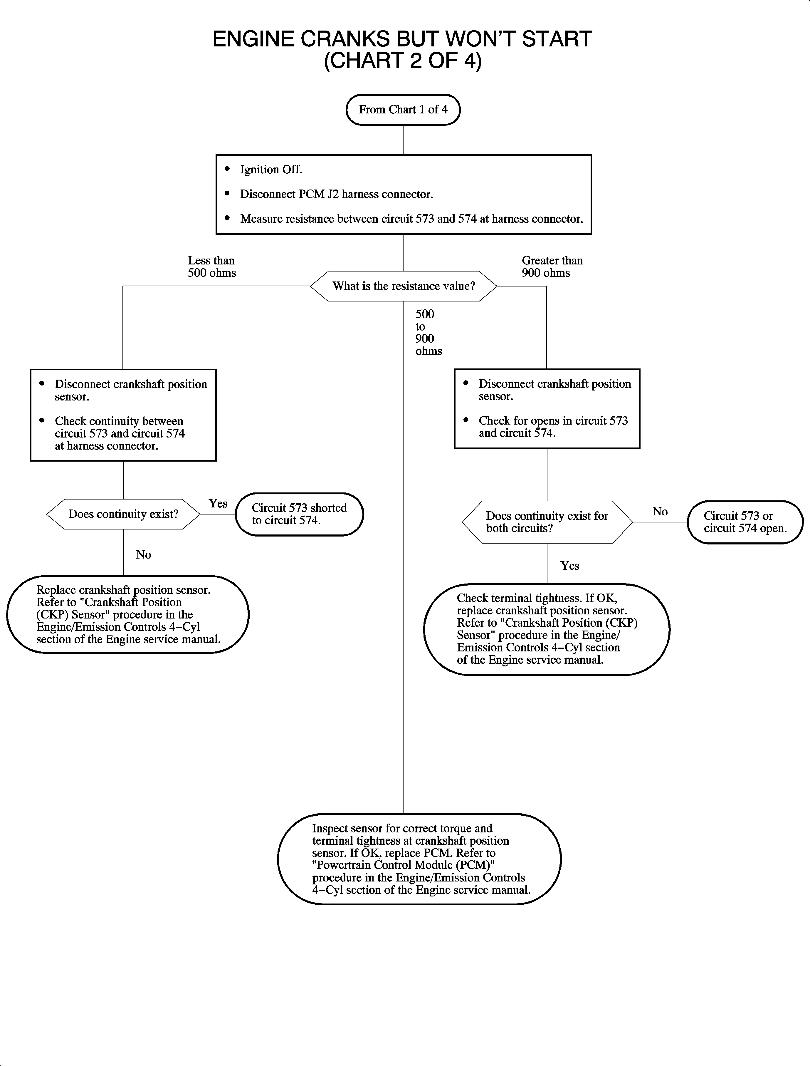
Engine Cranks But Won't Start (Chart 2 of 4 - No RPM Detected)
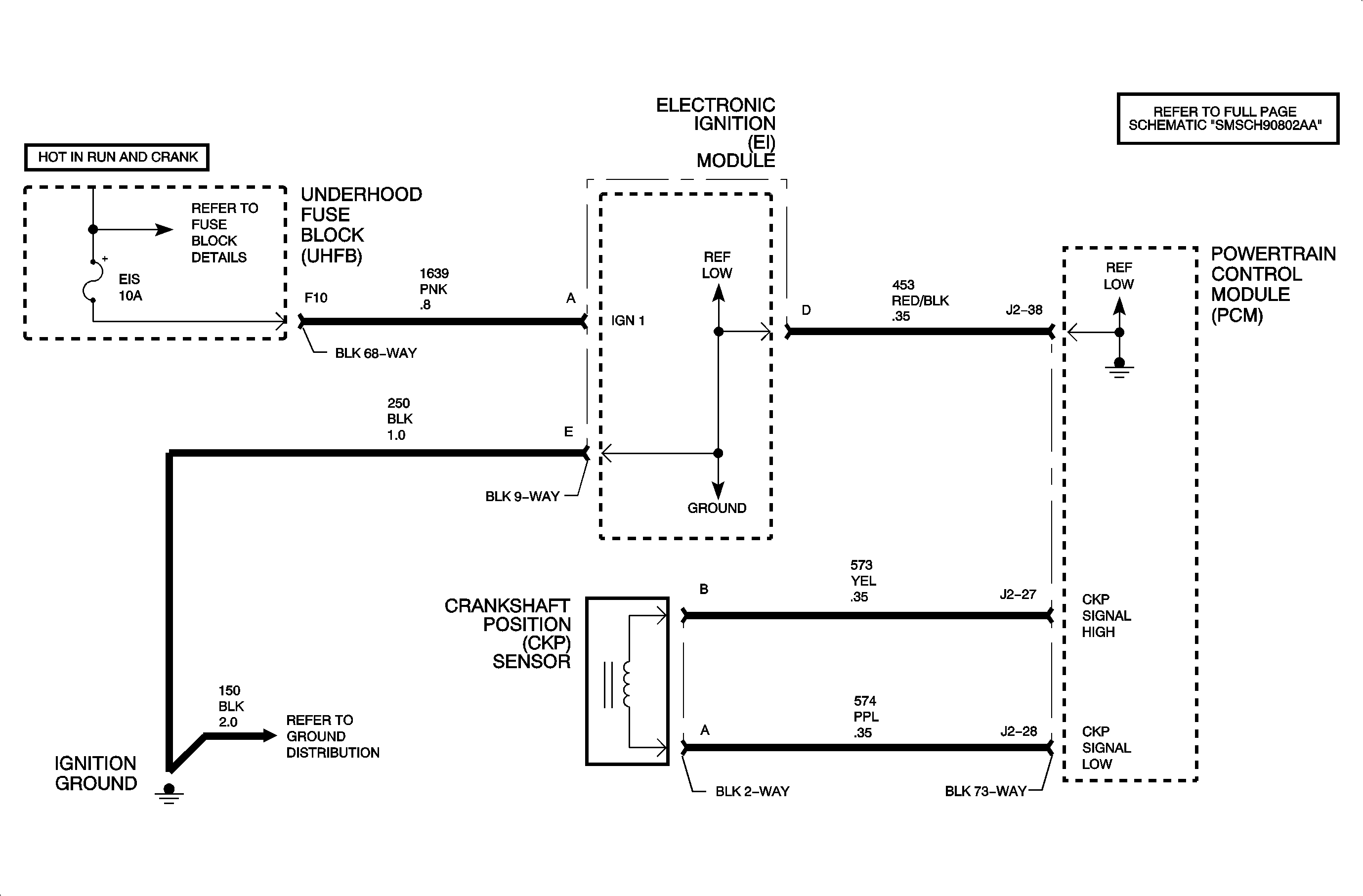
The crankshaft position (CKP) sensor produces an AC voltage of different amplitude and frequency depending on the velocity of the crankshaft. This AC voltage signal is fed to the PCM. The crankshaft has 7 total machined notches, 6 of which are spaced 60 degrees apart. The remaining tooth is 10 degrees before the #4 cylinder TDC notch. This extra notch is used by the PCM to determine the position of the top dead center #4 cylinder necessary to synchronize engine position. The CKP sensor is used for fuel delivery, spark timing, and misfire diagnostics.
Diagnostic Aids
If ENGINE SPEED on the scan tool does not indicate any RPM while the engine is cranking, the PCM will not look for a cam signal and the CMP ACTIVE COUNTER will stay at 0.
Intermittent CKP signal loss will cause the tachometer to dropout and may cause the engine to stall setting DTC P1599.
RPM may dropout as a result of a loose CKP sensor or resistance value that sharply changes due to temperature differences.
If the CKP sensor is tight and resistance values under different temperatures are correct, the sensor is probably not at fault.
The voltage between circuit 573 and 574 measured at the PCM harness connector (disconnected) while the engine is cranking should be over 200 mV AC.
CKP sensor resistance: 500-900 ohms.
Engine Cranks But Won't Start (Chart 3 of 4 - Ignition)
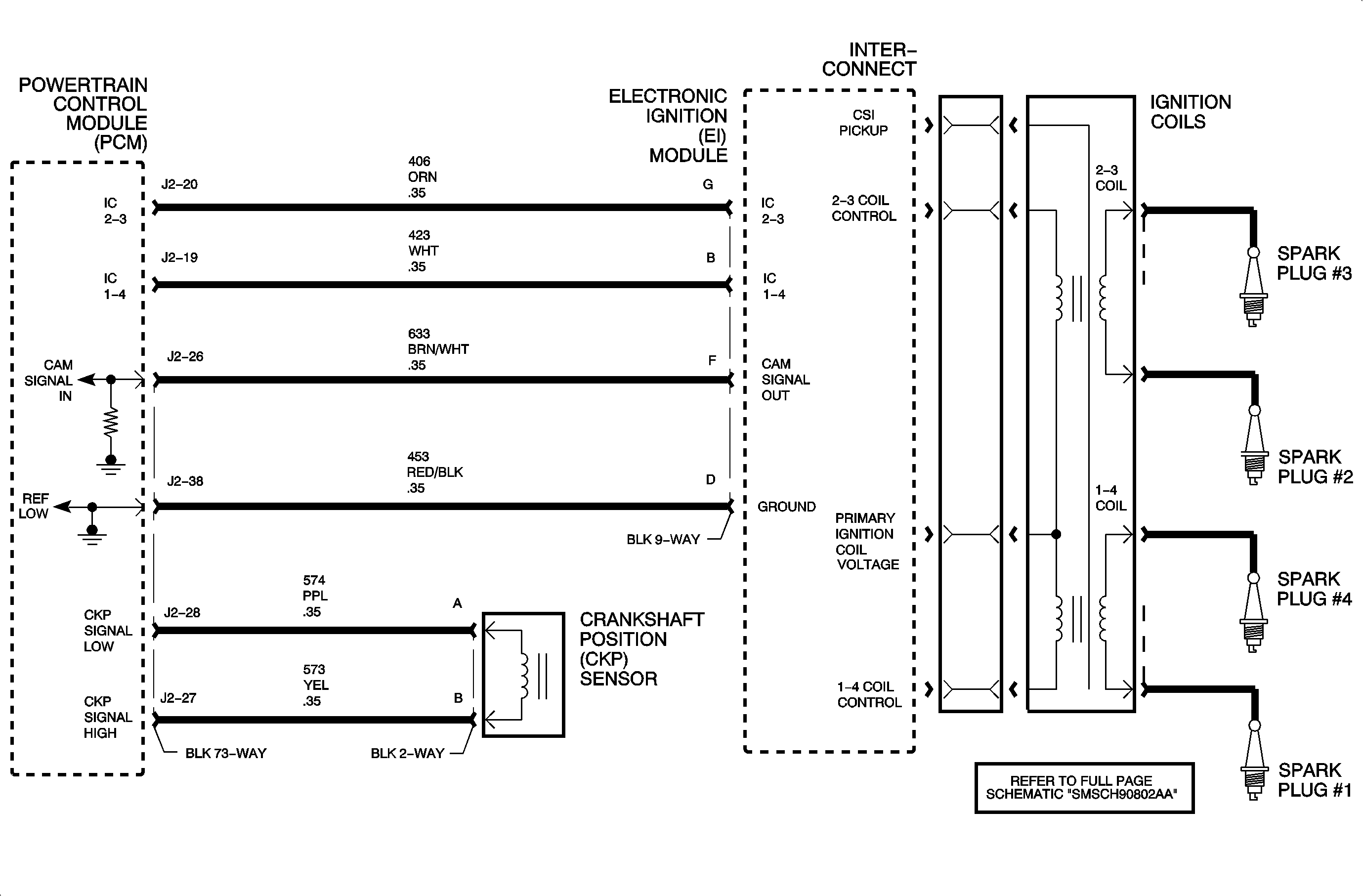
The PCM controls spark timing and dwell (spark on-time) under all engine running conditions. The electronic ignition (EI) module has the ability to charge and discharge each of the two coil packs independently based on PCM control. The PCM uses a high control signal of near 5 volts to charge up the coil and a low control signal of near 0 volts to discharge the coil. If the coil is charged and the control signal is low, the coil will fire through its secondary towers.
Diagnostic Aids
A missing cam pulse to the PCM from the EI module via circuit 633 will NOT effect engine starting.
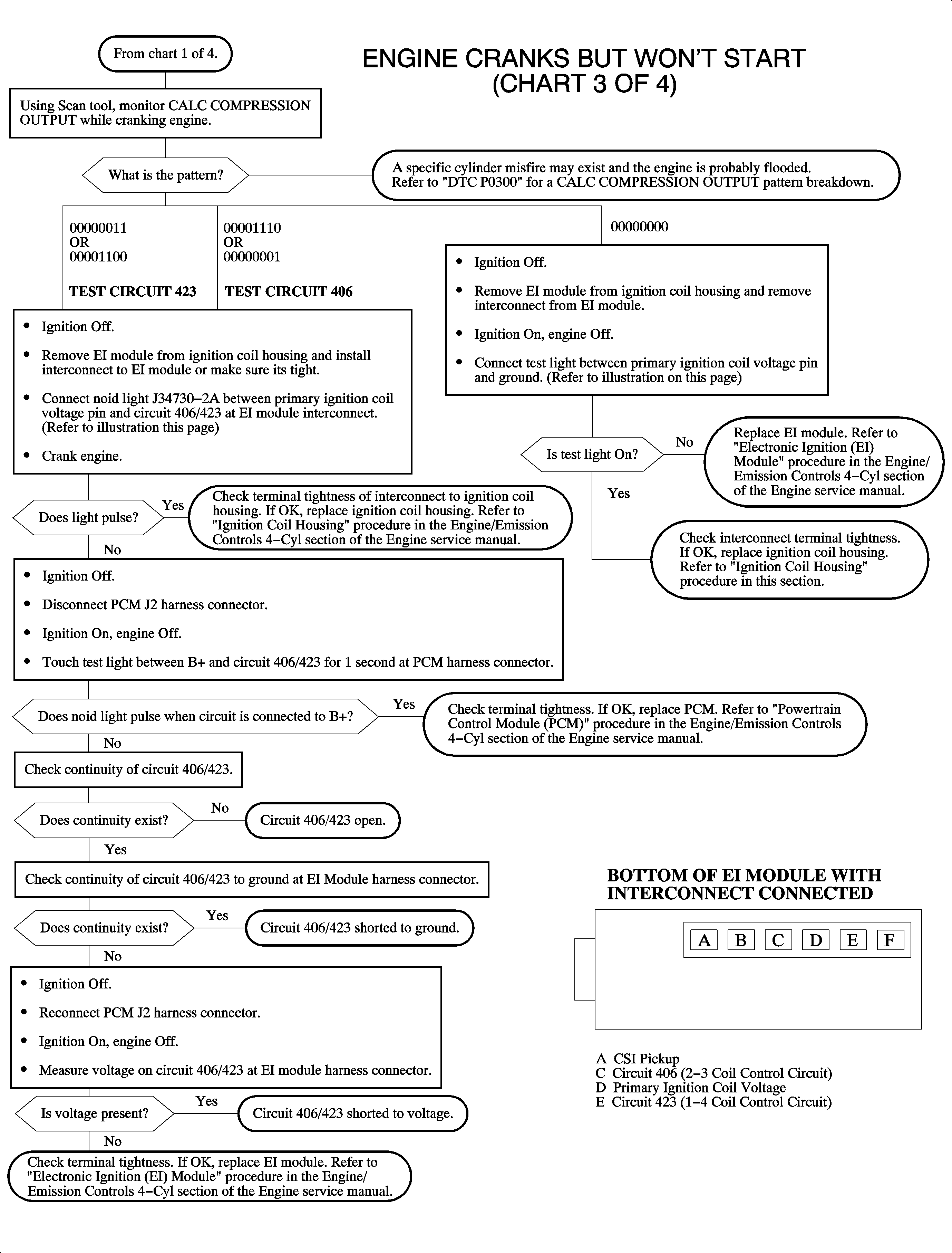
To determine if one of the two coils (1/4 or 2/3) is not firing, use the scan tool to monitor the CALC. COMPRESSION OUTPUT while cranking the engine.
| • | If the 1/4 primary or secondary coil or 1/4 control circuit is inoperative, the scan tool will display 00000110 or 00001100. |
| • | If the 2/3 primary or secondary coil or 2/3 control circuit is inoperative, the scan tool will display 00001110 or 00000001. |
The engine may or may not start on 2 cylinders.
Ignition voltage is supplied to the EI module and passed through the interconnect to the coils. If this circuit is open at the interconnect, neither coil will fire. ENGINE SPEED will indicate correctly, but CALC. COMPRESSION OUTPUT on the scan tool will remain at 00000000 when the engine is cranking.
Normal CALC. COMPRESSION OUTPUT with engine cranking or running should be 00000110 or 00001001 depending upon where the camshaft is.
Important: If a bit in CALC. COMPRESSION OUTPUT is changing from a 1 to a 0 or vice versa while the engine is cranking, an ignition problem or compression problem is occurring. Refer to DTC P0300 for specific fault bit patterns.
Primary ignition coil resistance: 0.4-1.6 ohms
Secondary ignition coil resistance (tower 1 to tower 4 or tower 2 to tower 3): 3.8-5.1 k ohms
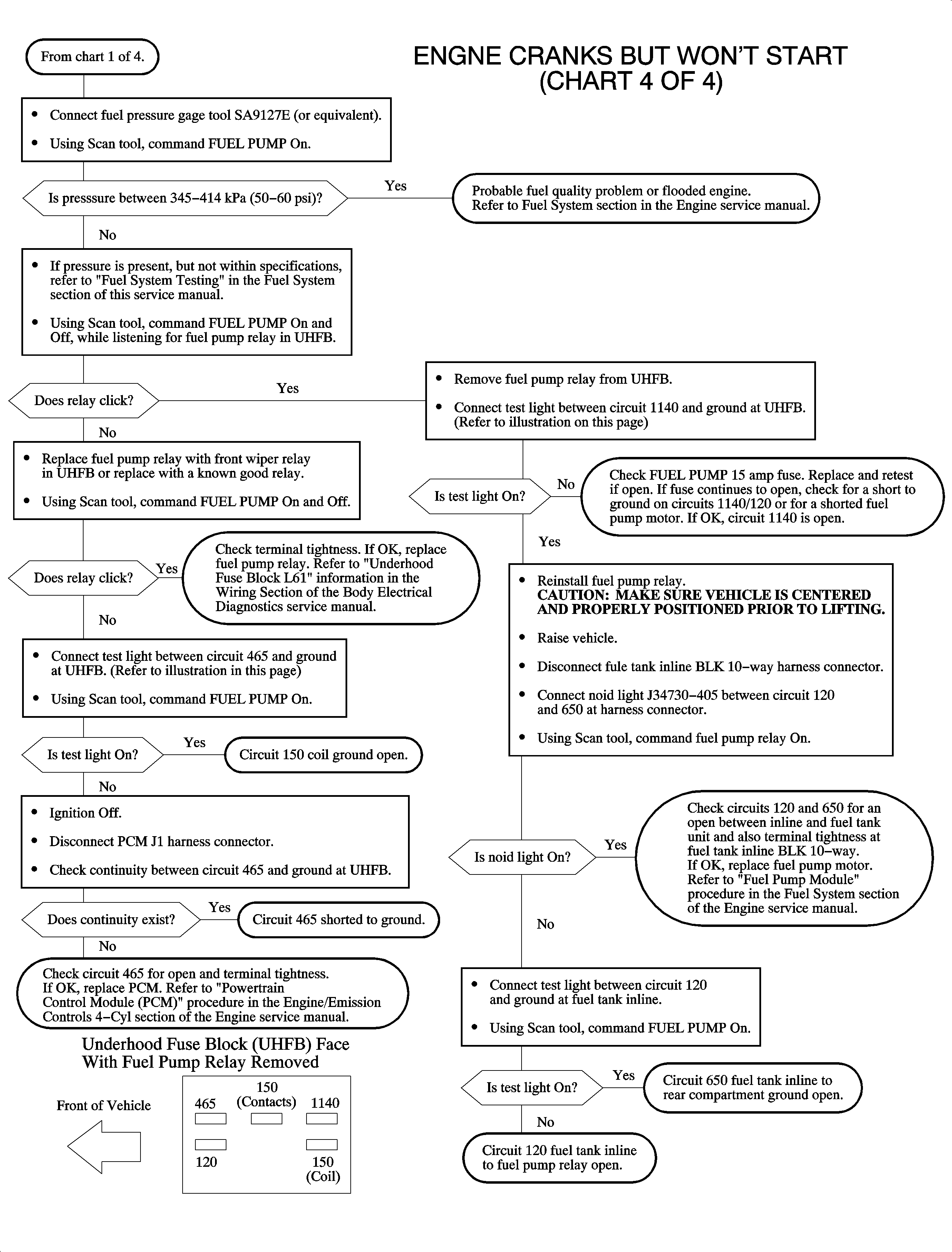
Engine Cranks But Won't Start - (Chart 4 of 4 - Fuel Delivery)
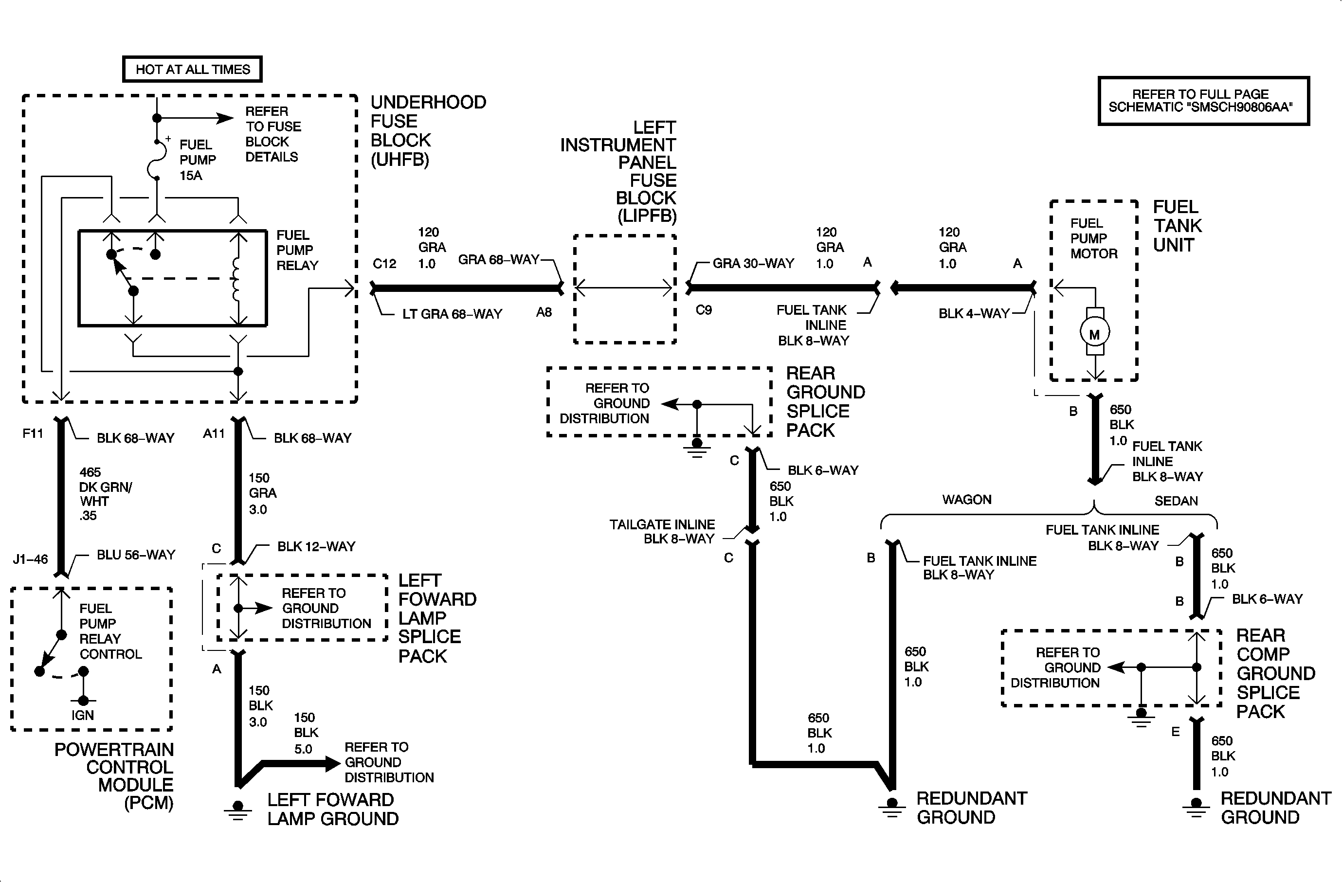
The PCM controls the fuel pump motor by supplying the fuel pump relay coil ignition voltage. The fuel pump runs continuously whenever the engine is running or runs for 2 seconds if the ignition is turned ON and the engine is not cranked. The PCM controls an internal driver, which supplies the fuel pump relay coil direct ignition voltage whenever the fuel pump is commanded ON. The fuel pump is fed battery voltage whenever the fuel pump relay is turned ON.
Diagnostic Aids
The fuel pump will run for 2 seconds when the ignition is first turned ON and no CKP signal is received at the PCM.
The scan tool can be used to command the FUEL PUMP ON and OFF instead of cycling the ignition key.
The ignition must be OFF for 10 seconds before the PCM will turn ON the fuel pump relay when no CKP signal is received at the PCM.
To perform an accurate fuel pressure reading, the fuel pump should be cycled 3 times.
Fuel pressure: 345-414 kPa (50-60 psi)
Fuel pump relay coil resistance: 70-115 ohms
