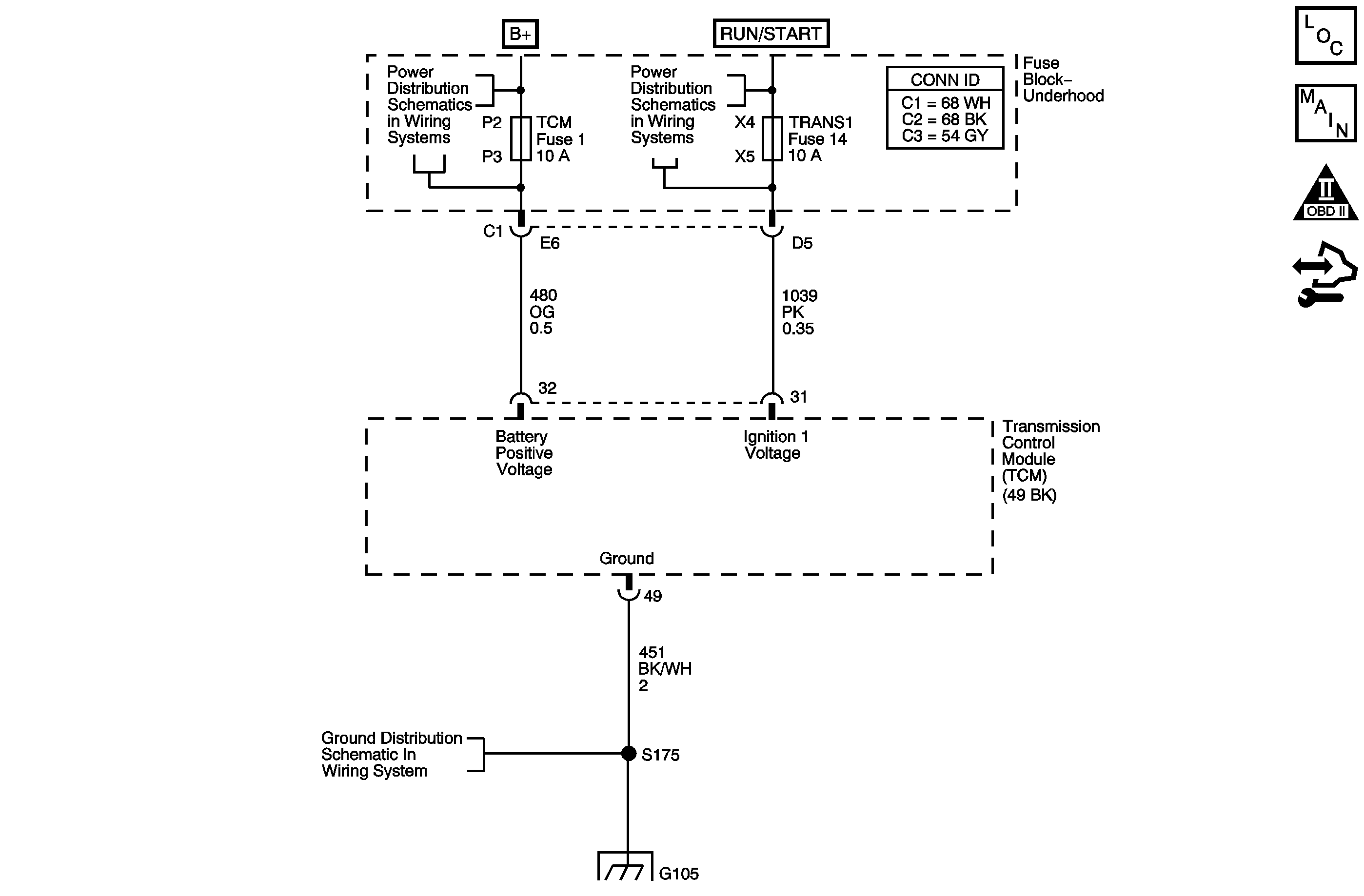
Circuit Description
The transmission control module (TCM) samples the system voltage on the ignition 1 circuit every 0.1 seconds. Higher than normal voltage may cause the transmission control solenoids to operate improperly or damage the solid-state components inside the TCM.
If the TCM detects high voltage for a number of samples, DTC P0563 sets. DTC P0563 is a type C DTC.
DTC Descriptor
This diagnostic procedure supports the following DTC:
DTC P0563 System Voltage High
Conditions for Running The DTC
The ignition is ON.
Conditions for Setting The DTC
The TCM detects system voltage is 18 volts or greater for 10 seconds.
Action Taken When the DTC Sets
| • | The TCM does not request the engine control module (ECM) to illuminate the malfunction indicator lamp (MIL). |
| • | The TCM records the operating conditions when the Conditions for Setting the DTC are met. The TCM stores this information as Failure Records. |
| • | The TCM stores DTC P0563 in TCM history. |
Conditions for Clearing the DTC
| • | A scan tool can clear the DTC. |
| • | The TCM clears the DTC from TCM history if the vehicle completes 40 warm-up cycles without a non-emission related diagnostic fault occurring. |
| • | The TCM cancels the DTC default actions when the ignition switch is OFF long enough in order to power down the TCM. |
Diagnostic Aids
| • | Use the scan tool in order to inspect all other modules for voltage related DTCs. |
| • | Running the engine with a battery charger attached may cause DTC P0563 to set. |
| - | Inspect the charging circuit for high resistance. |
| - | Inspect the vehicle battery for open or sulfated cells. |
Test Description
The numbers below refer to the step numbers on the diagnostic table.
-
This step tests the charging system voltage with a minimal load.
-
This step obtains the ignition voltage measurement reported by the TCM.
Step | Action | Values | Yes | No | ||||||||
|---|---|---|---|---|---|---|---|---|---|---|---|---|
1 | Did you perform the Diagnostic System Check - Vehicle? | -- | Go to Step 2 | |||||||||
2 |
Important:
Is the battery charge indicator lamp ON? | -- | Go to Step 3 | |||||||||
Is the voltage within the specified range? | 12.5-14.5 V | Go to Step 4 | Go to Charging System Test | |||||||||
Is the difference between the voltage displayed on the scan tool and the voltage measurement in Step 3 greater than the specified value? | 1.0 V | Go to Step 6 | Go to Step 5 | |||||||||
5 | Did DTC P0563 reset? | -- | Go to Step 6 | Go to Testing for Intermittent Conditions and Poor Connections | ||||||||
6 | Replace the TCM. Refer to Control Module References for replacement, setup, and programming. Did you complete the replacement? | -- | Go to Step 7 | -- | ||||||||
7 | Perform the following procedure in order to verify the repair:
Has the test run and passed? | -- | Go to Step 8 | Go to Step 2 | ||||||||
8 | With the scan tool, observe the stored information, capture info and DTC info. Does the scan tool display any DTCs that you have not diagnosed? | -- | System OK |
