For 1990-2009 cars only
Tools Required
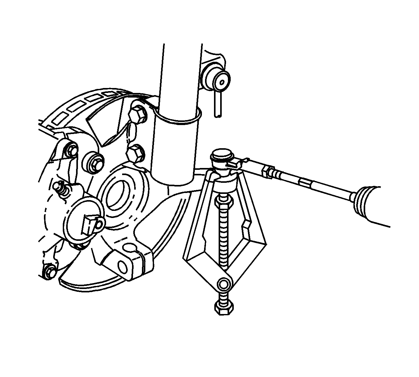
| • | SA91100C Tie Rod Separator |
| • | J 43631 Ball Joint Remover |
Removal Procedure
- Raise and support the vehicle. Refer to Lifting and Jacking the Vehicle .
- Remove the wheel bearing. Refer to Front Wheel Bearing and Hub Replacement .
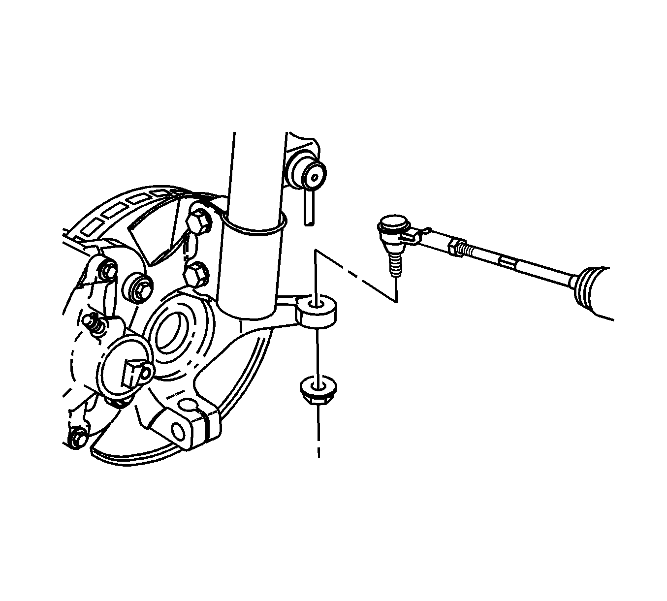
- Remove the outer tie rod to knuckle nut.
- Using the SA91100C , separate the tie rod from the steering knuckle.
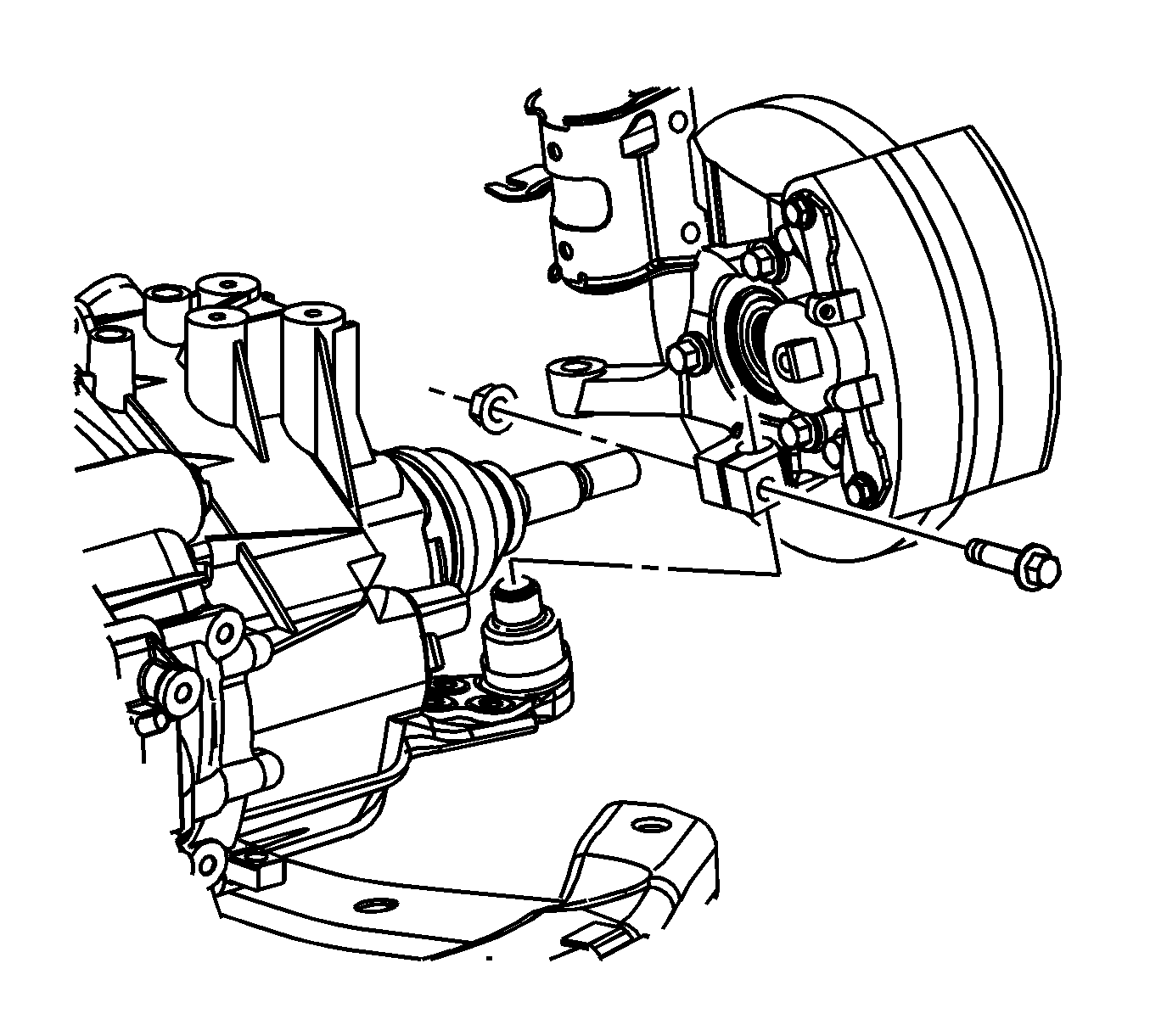
- Remove the lower control arm ball stud to steering knuckle pinch bolt and nut.
- Lower the lower control arm to separate the ball stud from the steering knuckle. If necessary, use the J 43631 .
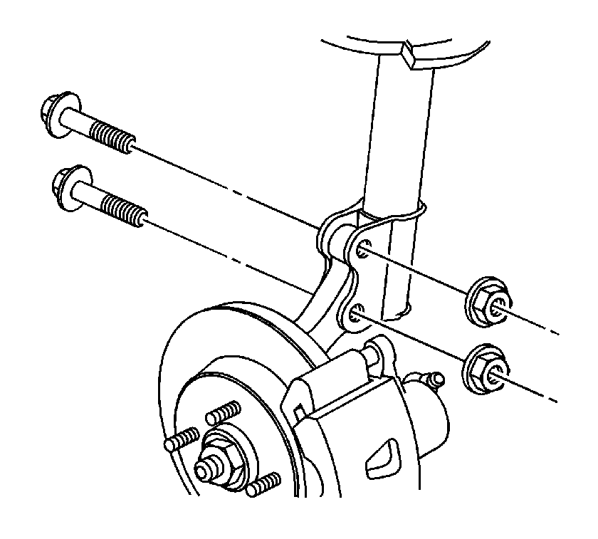
- Remove the strut to steering knuckle nuts and bolts.
- Remove the steering knuckle from the vehicle.


Notice: Do not free the ball stud by using a pickle fork or a wedge-type tool. Damage to the seal or bushing may result.

Installation Procedure
- Position the steering knuckle onto the lower control arm ball stud, while guiding the axle through the knuckle.
- Install the strut to knuckle bolts and nuts.
- Install the lower control arm ball stud to steering knuckle pinch bolt and nut.
- First Pass: Tighten the nut to 50 N·m (37 lb ft) .
- Reverse nut 3/4 turn
- Second Pass: Tighten the nut to 50 N·m (37 lb ft) plus 30 degrees.
- Install the outer tie rod to the steering knuckle.
- Install the wheel bearing, brake rotor, brake caliper and front wheels. Refer to Front Wheel Bearing and Hub Replacement .
- Lower the vehicle.
- Road test the vehicle in order to verify alignment. If a lead or pull is present refer to Wheel Alignment Measurement .
Notice: Refer to Fastener Notice in the Preface section.

Tighten
Tighten the bolts and nuts to 120 N·m (89 lb ft).

Important: The torque sequence must be followed in the order that is listed.
Tighten

Tighten
Tighten the nut to 25 N·m (18 lb ft) plus 90 degrees.
