| Connector 1: | Audio Amplifier C1 (UZ6) |
| Connector 2: | Audio Amplifier C2 (UZ6) |
| Connector 3: | Audio Amplifier C3 (UZ6) |
| Connector 4: | Digital Radio Receiver (U2K) |
| Connector 5: | Radio C1 |
| Connector 6: | Radio C2 |
| Connector 7: | Speaker - Left Front Door |
| Connector 8: | Speaker - Left Front Door Tweeter (UZ6) |
| Connector 9: | Speaker - Left Rear |
| Connector 10: | Speaker - Right Front Door |
| Connector 11: | Speaker - Right Front Door Tweeter (UZ6) |
| Connector 12: | Speaker - Right Rear |
| Connector 13: | Vehicle Communication Interface Module (VCIM) C1 |
| Connector 14: | Vehicle Communication Interface Module (VCIM) C2 |
Audio Amplifier C1 (UZ6)
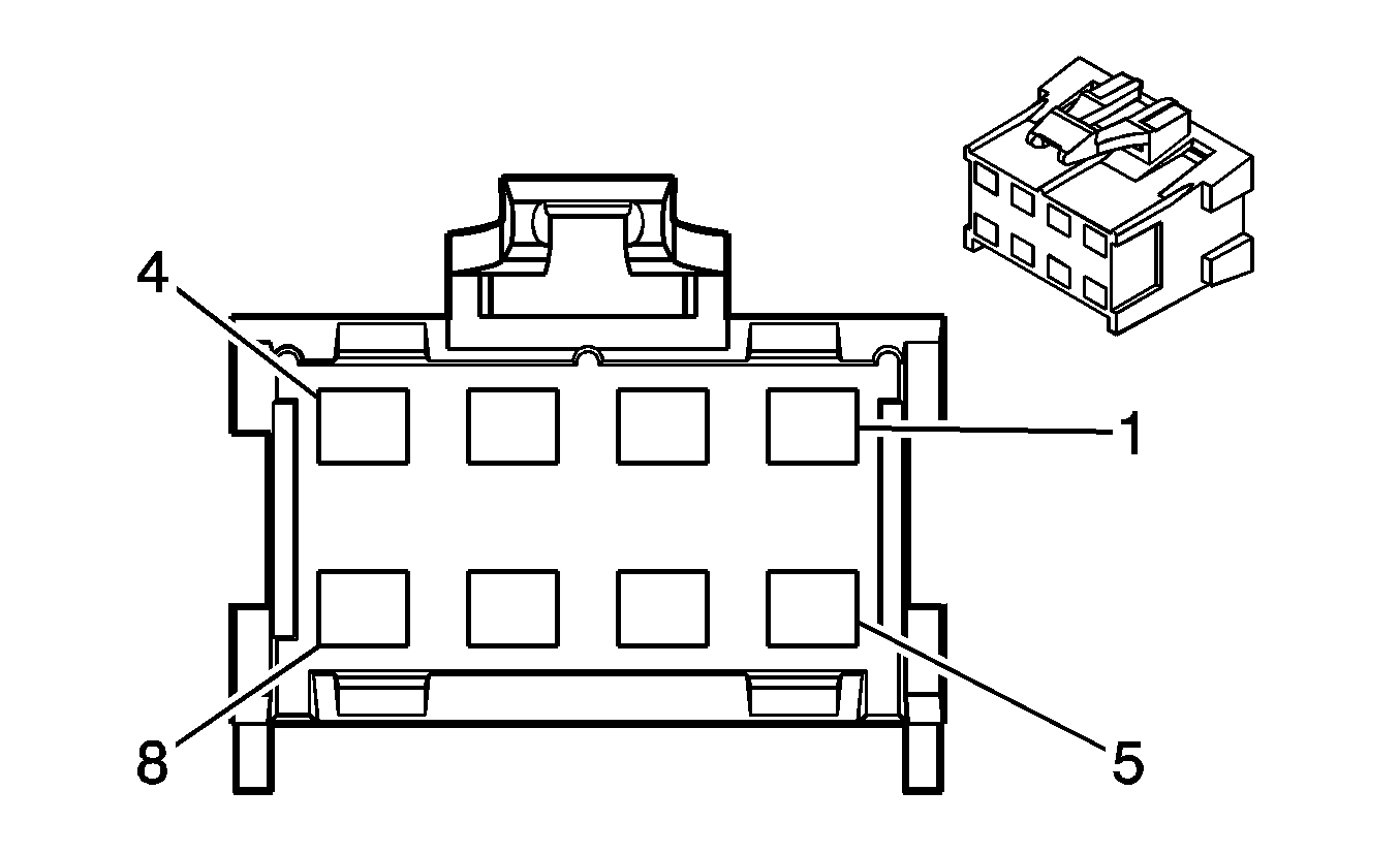
Connector Part Information
|
Terminal Part Information
|
Pin | Wire Color | Circuit No. | Function |
|---|---|---|---|
1-2 | -- | -- | Not Used |
3 | PK | 314 | Radio On Signal |
4 | OG | 1240 | Battery Positive Voltage |
5-6 | -- | -- | Not Used |
7 | L-GN | 1011 | Amplifier Mute Signal |
8 | BK | 750 | Ground |
Audio Amplifier C2 (UZ6)
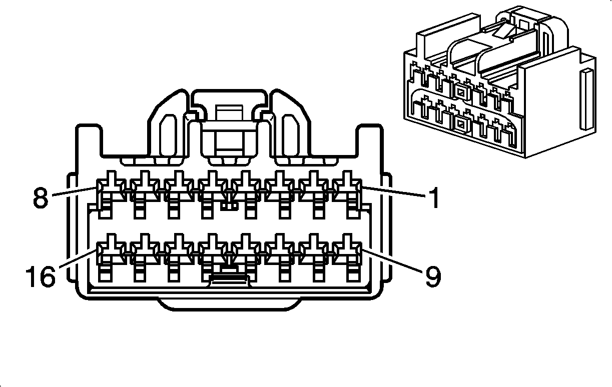
Connector Part Information
|
Terminal Part Information
|
Pin | Wire Color | Circuit No. | Function |
|---|---|---|---|
1 | -- | -- | Not Used |
2 | D-BU | 1857 | Left Front Speaker Output (-) |
3 | D-BU/WH | 346 | Left Subwoofer Speaker Output (+) |
4-5 | -- | -- | Not Used |
6 | OG | 1853 | Right Front Speaker Output (-) |
7 | D-GN | 1795 | Right Subwoofer Speaker Output (+) |
8-9 | -- | -- | Not Used |
10 | L-BU | 1957 | Left Front Speaker Output (+) |
11 | L-GN/BK | 1794 | Left Subwoofer Speaker Output (-) |
12-13 | -- | -- | Not Used |
14 | D-GN | 1953 | Right Front Speaker Output (+) |
15 | L-BU/BK | 315 | Right Subwoofer Speaker Output (-) |
16 | -- | -- | Not Used |
Audio Amplifier C3 (UZ6)
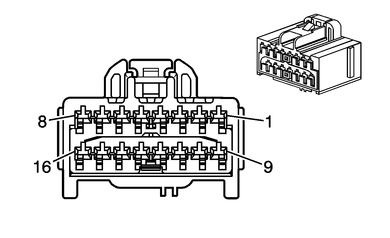
Connector Part Information
|
Terminal Part Information
|
Pin | Wire Color | Circuit No. | Function |
|---|---|---|---|
1 | TN | 201 | Left Front Speaker Output (+) |
2 | L-GN | 200 | Right Front Speaker Output (+) |
3 | BN | 199 | Left Rear Speaker Output (+) |
4 | D-BU | 46 | Right Rear Speaker Output (+) |
5-8 | -- | -- | Not Used |
9 | GY | 118 | Left Front Speaker Output (-) |
10 | D-GN | 117 | Right Front Speaker Output (-) |
11 | YE | 116 | Left Rear Speaker Output (-) |
12 | L-BU | 115 | Right Rear Speaker Output (-) |
13-16 | -- | -- | Not Used |
Digital Radio Receiver (U2K)
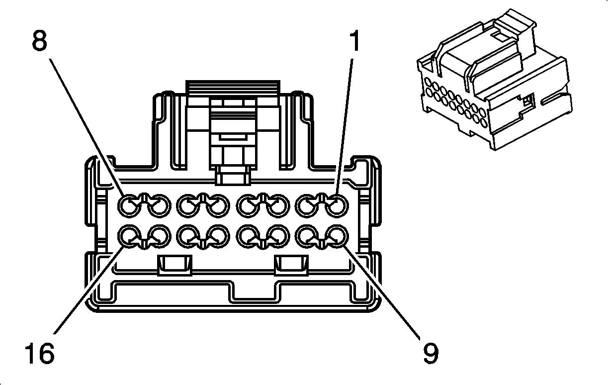
Connector Part Information
|
Terminal Part Information
|
Pin | Wire Color | Circuit No. | Function |
|---|---|---|---|
1 | -- | -- | Not Used |
2 | BN/WH | 367 | Left Audio Signal (+) |
3 | D-GN/WH | 368 | Right Audio Signal (+) |
4 | -- | -- | Not Used |
5 | D-GN | 5060 | Low Speed GM LAN Serial Data |
6-8 | -- | -- | Not Used |
9 | BK/WH | 751 | Ground |
10 | BK/WH | 372 | Audio Common |
11 | BARE | 814 | Drain Wire |
12-15 | -- | -- | Not Used |
16 | OG | 1340 | Battery Positive Voltage |
Radio C1
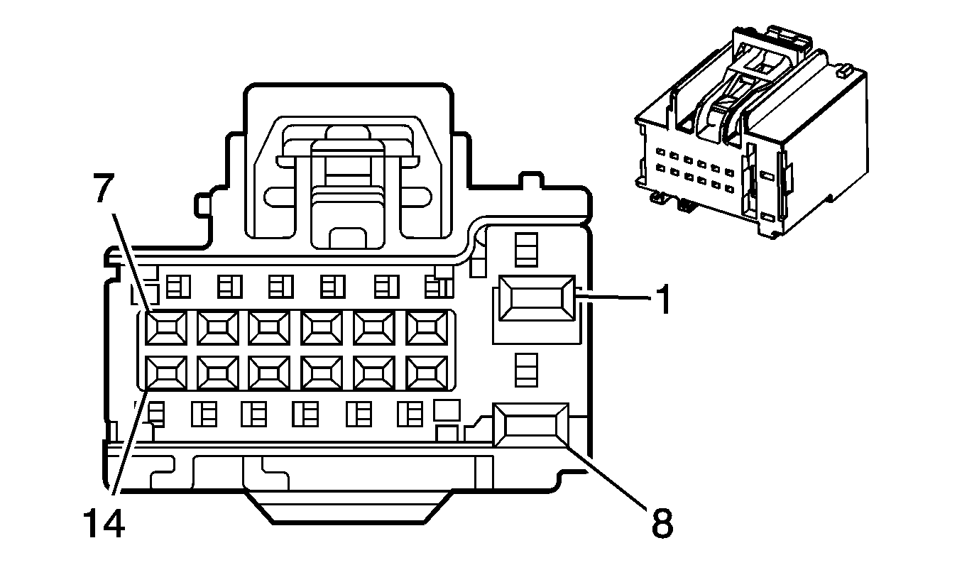
Connector Part Information
|
Terminal Part Information
|
Pin | Wire Color | Circuit No. | Function |
|---|---|---|---|
1 | OG | 1140 | Battery Positive Voltage |
2 | GY | 8 | Instrument Panel Lamps Supply Voltage |
3 | -- | -- | Not Used |
4 | D-GN | 117 | Right Front Speaker Output (-) |
5 | L-GN | 200 | Right Front Speaker Output (+) |
6 | GY | 118 | Left Front Speaker Output (-) |
7 | TN | 201 | Left Front Speaker Output (+) |
8 | BK/WH | 151 | Ground |
9 | D-GN | 5060 | Low Speed GMLAN Serial Data |
10 | D-GN | 5060 | Low Speed GMLAN Serial Data |
11-13 | -- | -- | Not Used |
14 | YE | 343 | Accessory Voltage |
Radio C2
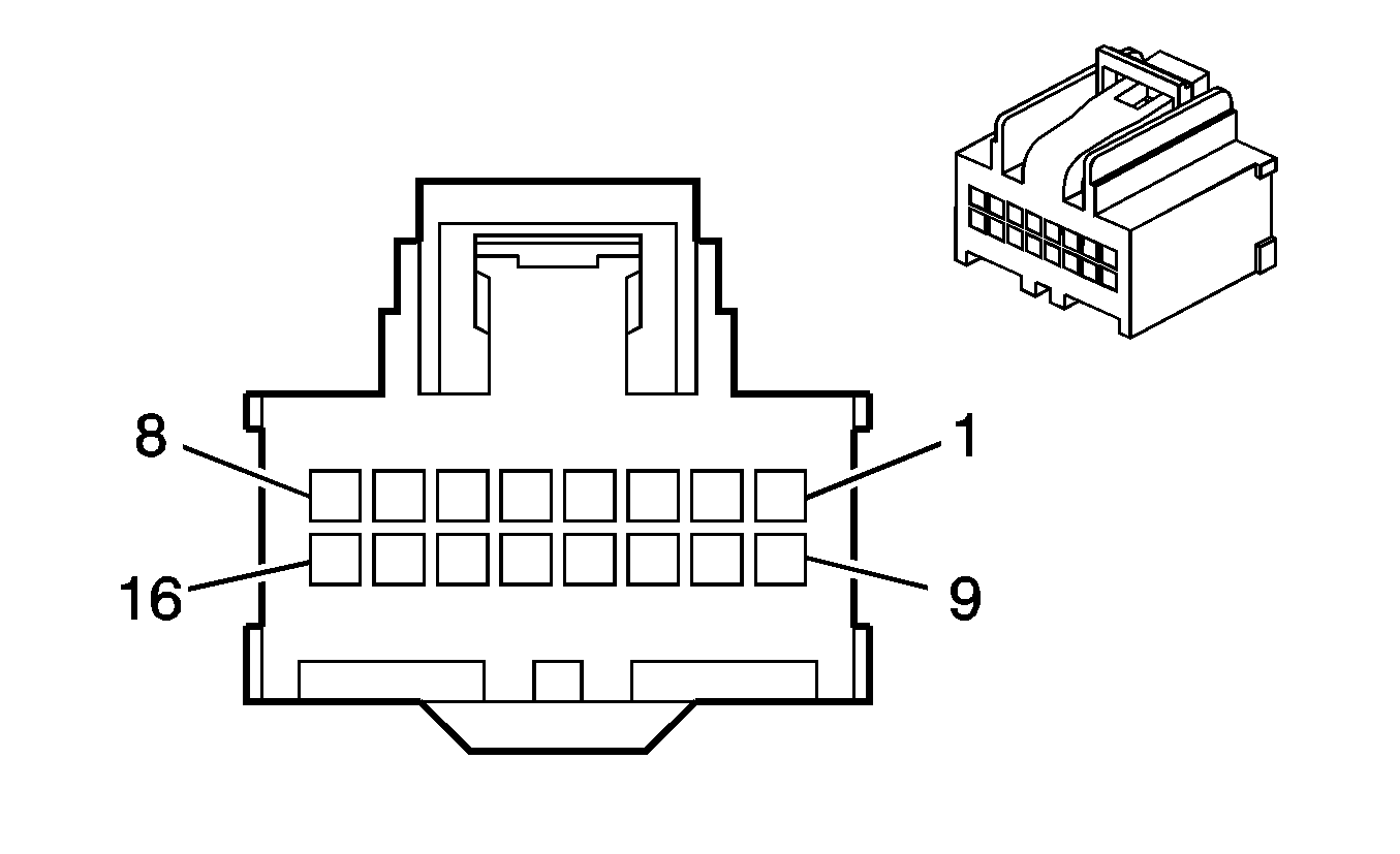
Connector Part Information
|
Terminal Part Information
|
Pin | Wire Color | Circuit No. | Function |
|---|---|---|---|
1 | BN/WH | 367 | Left Audio Signal |
2 | D-GN/WH | 368 | Right Audio Signal |
3 | PK | 314 | Radio On Signal |
4 | D-BU | 46 | Right Rear Speaker Output (+) |
5 | L-BU | 115 | Right Rear Speaker Output (-) |
6 | BN | 199 | Left Rear Speaker Output (+) |
7 | YE | 116 | Left Rear Speaker Output (-) |
8 | PK/BK | 2062 | Remote Radio Left Audio Signal (UE1) |
9 | BK/WH | 372 | Audio Common |
10 | YE/BK | 693 | Cellular Telephone Mute Signal (UE1) |
11 | -- | -- | Not Used |
12 | BN | 9 | Park Lamp Supply Voltage |
13-14 | -- | -- | Not Used |
15 | L-GN | 1011 | Amplifier Mute Signal |
16 | OG-BK | 2061 | Remote Radio Audio Output (-) (UE1) |
Speaker - Left Front Door
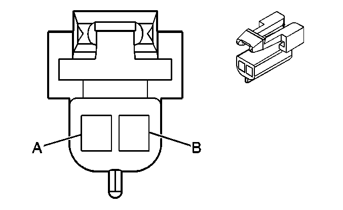
Connector Part Information
|
Terminal Part Information
|
Pin | Wire Color | Circuit No. | Function |
|---|---|---|---|
A | L-BU | 1957 | Left Front Midrange Speaker Output (-) |
B | D-BU | 1857 | Left Front Midrange Speaker Output (+) |
Speaker - Left Front Door Tweeter (UZ6)

Connector Part Information
|
Terminal Part Information
|
Pin | Wire Color | Circuit No. | Function |
|---|---|---|---|
A | L-BU | 1957 | Left Front Midrange Speaker Output (-) |
B | D-BU | 1857 | Left Front Midrange Speaker Output (+) |
Speaker - Left Rear

Connector Part Information
|
Terminal Part Information
|
Pin | Wire Color | Circuit No. | Function |
|---|---|---|---|
A | YE | 116 | Left Rear Speaker Output (-) (US8 w/U79 or UX7) |
L-GN/BK | 1794 | Left Subwoofer Speaker Output (-) (UZ6) | |
B | BN | 199 | Left Rear Speaker Output (+) (US8 w/U79 or UX7) |
D-BU/WH | 346 | Left Subwoofer Speaker Output (+) (UZ6) |
Speaker - Right Front Door

Connector Part Information
|
Terminal Part Information
|
Pin | Wire Color | Circuit No. | Function |
|---|---|---|---|
A | D-GN | 117 | Right Front Speaker Output (-) (US8 w/U79 or UX7) |
1953 | Right Front Midrange Speaker Output (-) (UZ6) | ||
B | L-GN | 200 | Right Front Speaker Output (+) (US8 w/U79 or UX7) |
OG | 1853 | Right Front Midrange Speaker Output (+) (UZ6) |
Speaker - Right Front Door Tweeter (UZ6)

Connector Part Information
|
Terminal Part Information
|
Pin | Wire Color | Circuit No. | Function |
|---|---|---|---|
A | D-GN | 1953 | Right Front Midrange Speaker Output (-) |
B | OG | 1853 | Right Front Midrange Speaker Output (+) |
Speaker - Right Rear

Connector Part Information
|
Terminal Part Information
|
Pin | Wire Color | Circuit No. | Function |
|---|---|---|---|
A | L-BU | 115 | Right Rear Speaker Output (-) (US8 w/U79 or UX7) |
L-BU/BK | 315 | Right Subwoofer Speaker Output (-) (UZ6) | |
B | D-BU | 46 | Right Rear Speaker Output (+) (US8 w/U79 or UX7) |
D-GN | 1795 | Right Subwoofer Speaker Output (+) (UZ6) |
Vehicle Communication Interface Module (VCIM) C1
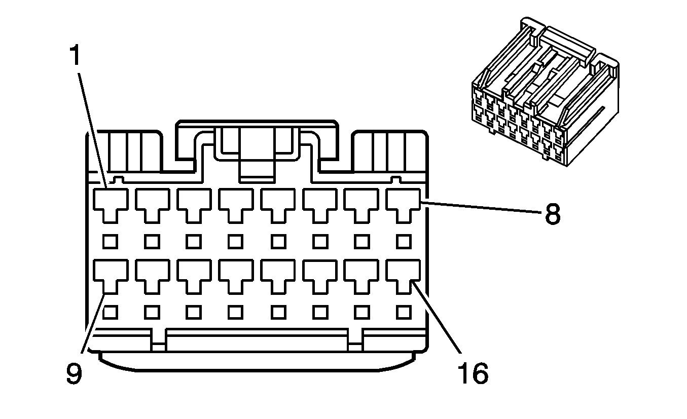
Connector Part Information
|
Terminal Part Information
|
Pin | Wire Color | Circuit No. | Function |
|---|---|---|---|
1 | -- | -- | Not Used |
2 | BN/WH | 2517 | Keypad Red LED Signal |
3 | YE/BK | 2516 | Keypad Green LED Signal |
4-5 | -- | -- | Not Used |
6 | L-GN/BK | 2515 | Keypad Supply Voltage |
7 | -- | -- | Not Used |
8 | BK/WH | 751 | Ground |
9-10 | -- | -- | Not Used |
11 | D-GN/WH | 2514 | Keypad Signal |
12-14 | -- | -- | Not Used |
15 | OG | 1340 | Battery Positive Voltage |
16 | -- | -- | Not Used |
Vehicle Communication Interface Module (VCIM) C2
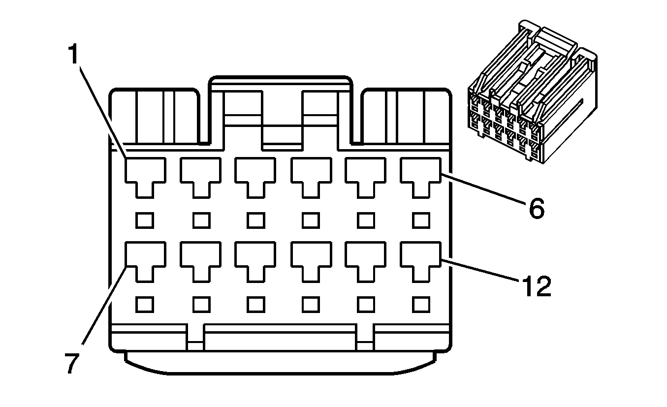
Connector Part Information
|
Terminal Part Information
|
Pin | Wire Color | Circuit No. | Function |
|---|---|---|---|
1 | PK/BK | 2062 | Cellular Telephone Voice Signal |
2 | OG/BK | 2061 | Cellular Telephone Voice Low Reference |
3-5 | -- | -- | Not Used |
6 | PU | 1807 | Class 2 Serial Data |
7 | -- | -- | Not Used |
8 | BARE | 814 | Drain Wire |
9 | GY | 655 | Cellular Microphone Signal |
10 | D-GN | 654 | Cellular Telephone Microphone Low Reference |
11 | -- | -- | Not Used |
12 | YE/BK | 693 | Cellular Telephone Mute Signal |
