Service Manual Update for Manual Shift Control Assembly Replacement and Shift Control Cable Replacement

| Subject: | Service Manual Update for Manual Shift Control Assembly Replacement and Shift Control Cable Replacement |
| Models: | 2004-2005 Saturn ION Red Line Vehicles with 5-Speed Manual Transmission (RPO MU3) |
| Attention: | Technician |
Purpose
The purpose of this bulletin is to inform technicians that the Manual Shift Control Assembly Replacement and the Shift Control Cable Replacement procedures have been updated in SI.
Please obtain all 2005 ION Transmission Volume 3 Service Manuals and insert the included procedures in the Manual Transaxle - MU3 section.
Procedure
Shift Control Assembly Replacement
Removal Procedure
- Remove the console top cover. Refer to Console Replacement - Front Floor (SI Document ID #884130) in the Instrument Panel, Gages, and Console section of the 2004 or 2005 ION Service Manual.
- Remove the shift cables from the shifter assembly. Refer to Shift Control Cable Replacement (SI Document ID #1386867) in the 2004 or 2005 ION Service Manual.
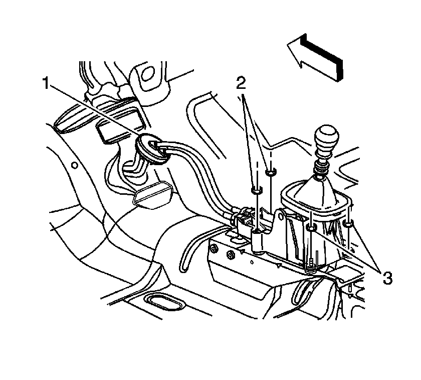
- Remove the two front mounting nuts (2).
- Remove the two rear mounting nuts (3) and the shifter.
Installation Procedure
- Position the shifter on the studs and install the front two nuts (2).
- Install the two rear nuts (3).
- Install the shift cables from the shifter assembly. Refer to Shift Control Cable Replacement (SI Document ID #1386867) in the 2004 or 2005 ION Service Manual.
- Install the console. Refer to Console Replacement - Front Floor (SI Document ID #884130) in the Instrument Panel, Gages, and Console section of the 2004 or 2005 ION Service Manual.

Notice: Use the correct fastener in the correct location. Replacement fasteners must be the correct part number for that application. Fasteners requiring replacement or fasteners requiring the use of thread locking compound or sealant are identified in the service procedure. Do not use paints, lubricants, or corrosion inhibitors on fasteners or fastener joint surfaces unless specified. These coatings affect fastener torque and joint clamping force and may damage the fastener. Use the correct tightening sequence and specifications when installing fasteners in order to avoid damage to parts and systems.
Tighten
Tighten nuts to 25N·m(18 ft-lbs).
Shift Control Cable Replacement
Removal Procedure
- Apply the parking brake.
- Shift the transmission to 4th gear.
- Remove the console. Refer to Console Replacement - Front Floor (SI Document ID #884130) in the Instrument Panel, Gages, and Console section of the 2004 or 2005 ION Service Manual.
- Lift up the cable retainers.
- Disconnect cable ends from the shift control assembly, noting the location for assembly.
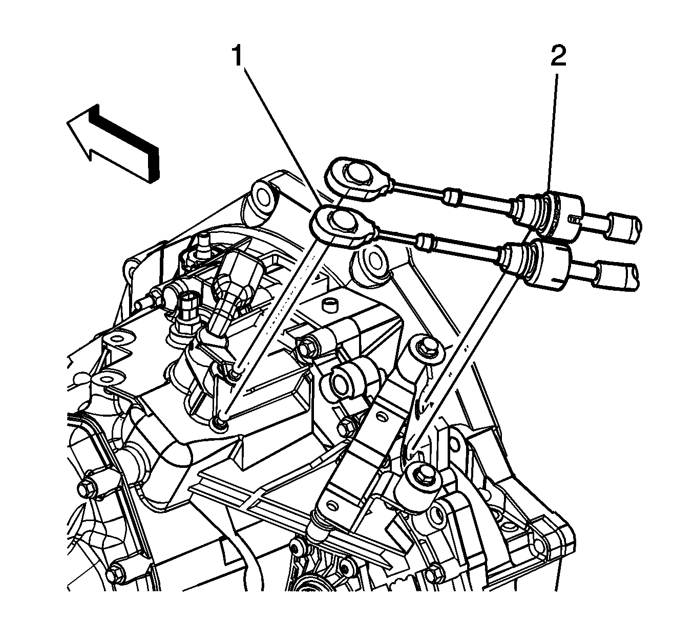
- Disconnect the cable ends (1) from the transmission shift levers, noting the location for assembly.
- Remove the shift cable (2) from the transmission cable bracket.
- Raise and support the vehicle. Refer to Lifting and Jacking the Vehicle (SI Document ID #878849) in the General Information section of the 2004 or 2005 ION Service Manual.
- Remove the shift cable attachment nut from the underbody.
- Lower the vehicle.
- Remove the left instrument panel closeout panel. Refer to Instrument Panel (I/P) Trim Panel Replacement - Left (SI Document ID #882449) in the Instrument Panel, Gages and Console section of the 2004 or 2005 ION Service Manual.
- Position the driver's side front carpet aside. Refer to Carpet Replacement (SI Document ID #873469) in the Interior Trim section of the 2004 or 2005 ION Service Manual.
- Separate the grommet (1) from the floor pan.
- Remove the cable from the vehicle by pulling the cables through the driver's floor opening.
Caution: To avoid any vehicle damage, serious personal injury or death when major components are removed from the vehicle and the vehicle is supported by a hoist, support the vehicle with jack stands at the opposite end from which the components are being removed.
Caution: To avoid any vehicle damage, serious personal injury or death, always use the jack stands to support the vehicle when lifting the vehicle with a jack.

Installation Procedure
- Feed the cable assembly through the driver's floor opening.
- Install the grommet (1) flush with the floor opening.
- Install the driver's side front carpet. Refer to Carpet Replacement (SI Document ID #873469) in the Interior Trim section of the 2004 or 2005 ION Service Manual.
- Install the left instrument panel closeout panel. Refer to Instrument Panel (I/P) Trim Panel Replacement - Left (SI Document ID #882449) in the Instrument Panel, Gages and Console section of the 2004 or 2005 ION Service Manual.
- Raise the vehicle. Refer to Lifting and Jacking the Vehicle (SI Document ID #878849) in the General Information section of the 2004 or 2005 ION Service Manual.
- Install the shift cable attachment nut to the underbody.
- Lower the vehicle.
- Install the shift cables (2) to the transmission cable bracket.
- Connect the shift cable ends (1) to the transmission shift levers as noted during disassembly.
- Connect the shift cable to the shift control assembly as noted during disassembly.
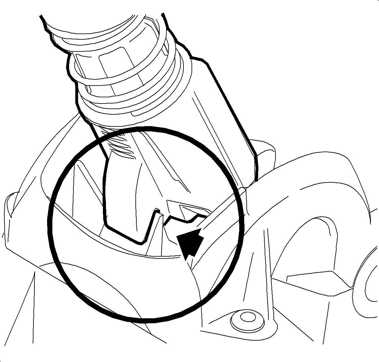
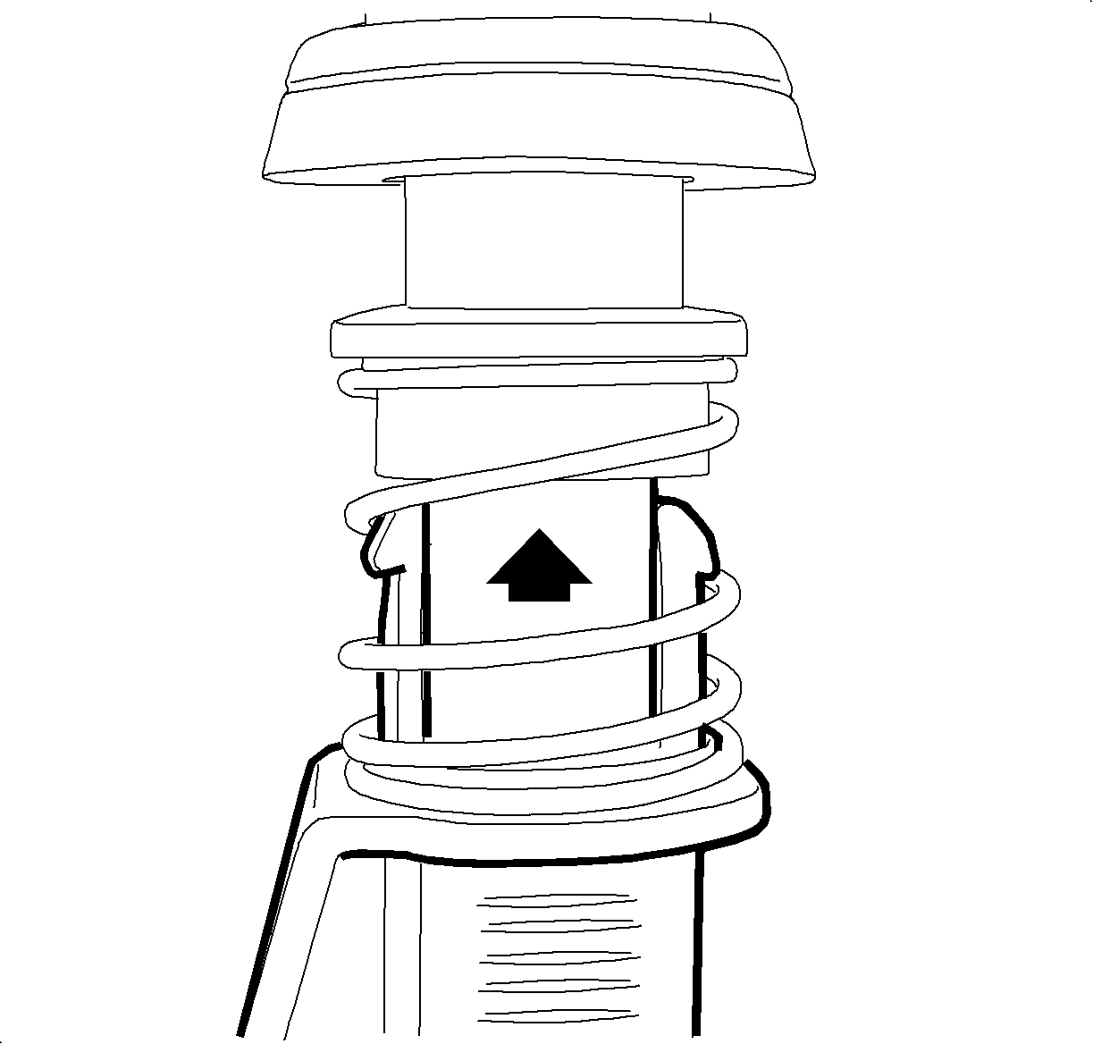
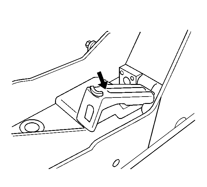
- Release the Shift Control Assembly 4th gear locking tab. Pull up on the shifter ring, install locking pliers as shown and rotate the pliers upwards to compress the tabs and release the 4th gear locking tab.
- Engage the 4th gear locking tab on the Shift Control Assembly housing.
- Ensure that the transmission is in 4th gear.
- Press down on the cable retainers.
- Pull the Shift Control Assembly 4th gear locking tab upwards to its original position. Ensure the 4th gear locking tab retainers are fully engaged in the shifter ring.
- Install the console. Refer to Console Replacement - Front Floor (SI Document ID #884130) in the Instrument Panel, Gages, and Console section of the 2004 or 2005 ION Service Manual.

Caution: To avoid any vehicle damage, serious personal injury or death when major components are removed from the vehicle and the vehicle is supported by a hoist, support the vehicle with jack stands at the opposite end from which the components are being removed.
Caution: To avoid any vehicle damage, serious personal injury or death, always use the jack stands to support the vehicle when lifting the vehicle with a jack.
Tighten
Tighten the nut to 10N·m(89 in-lbs).

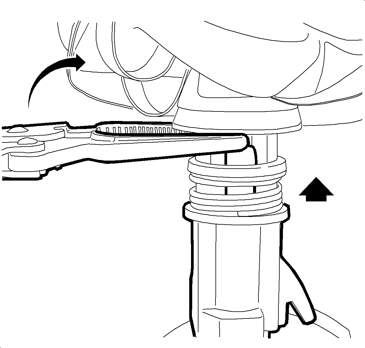
Notice: Care must be taken when releasing the 4th gear locking tab. The shifter ring must be pulled upwards to allow 4th gear locking tab to fully release. Excessive clamping force may damage plastic Shift Control Assembly components.
