For 1990-2009 cars only
Brake Pedal Assembly Replacement w/RPO L61
Removal Procedure
- Release the electric power steering (EPS) wiring harness from the brake pedal bracket.
- Remove the cruise control module, if equipped, from the brake pedal bracket. Refer to Cruise Control Module Replacement in Cruise Control.
- Remove the accelerator pedal mounting nuts. Reposition the accelerator pedal to improve tool access to the LH, lower booster mounting nut. Refer to Accelerator Pedal Replacement in Engine Controls - 2.2L.
- Loosen the brake booster mounting nuts.
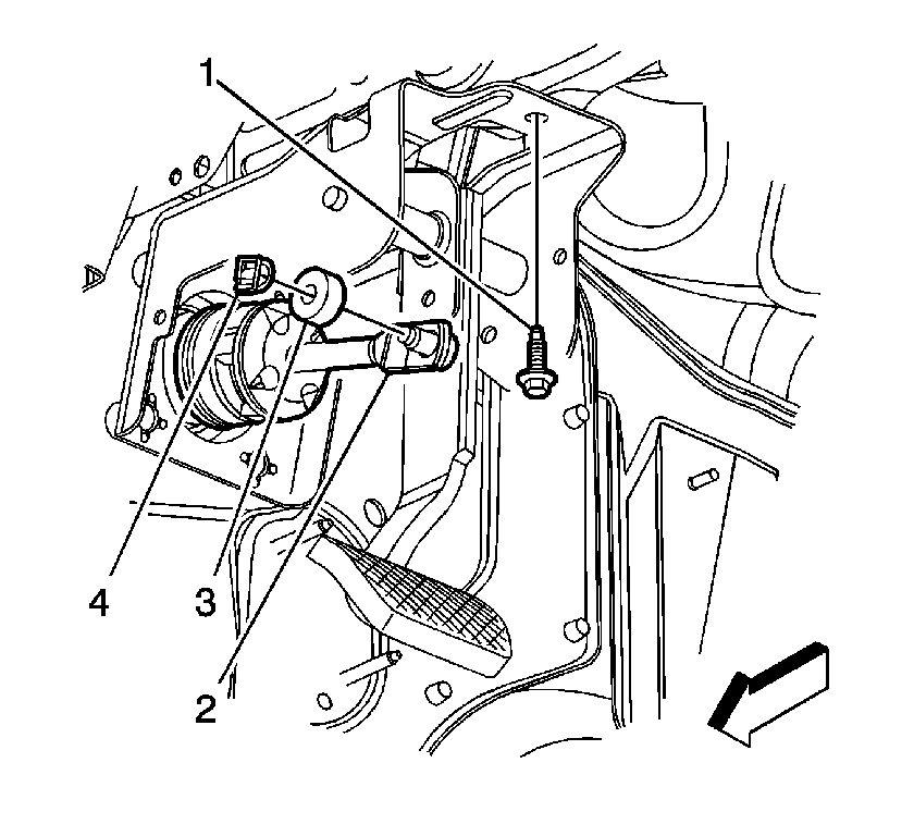
- Remove the retaining clip (4) and washer (3) from the brake pedal.
- Release the brake booster pushrod (2) from the brake pedal.
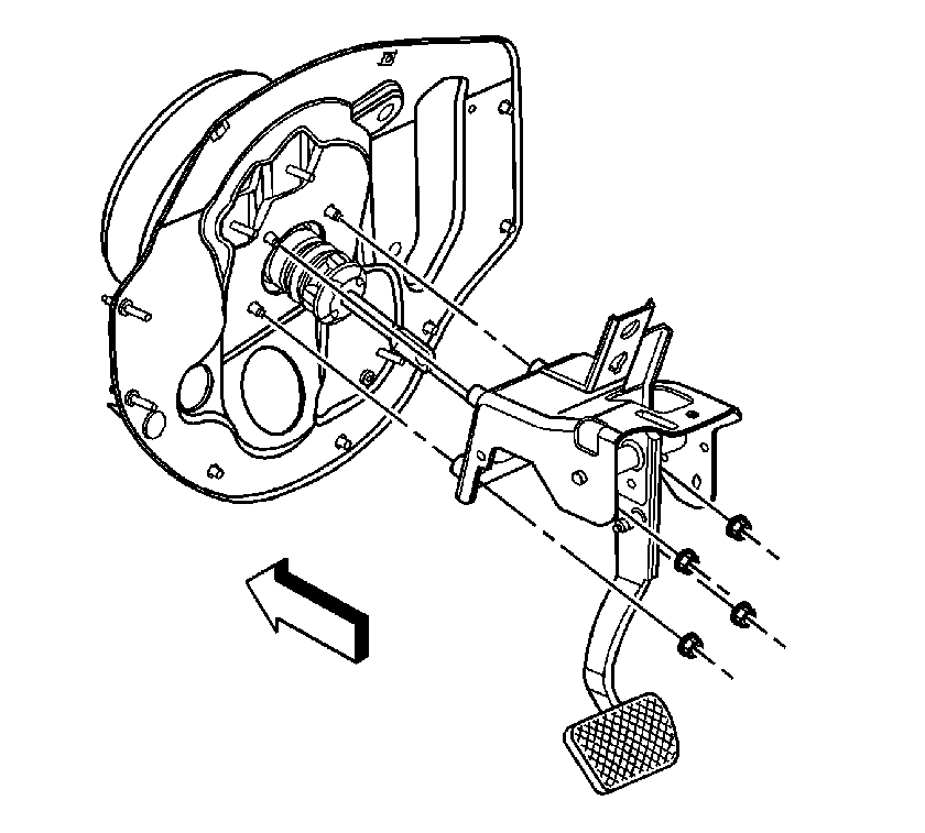
- Remove the brake booster mounting nuts.
- Remove the brake pedal bracket-to-steering column bracket bolt (1).
- Lower the brake pedal assembly to improve access for switch removal.
- Remove the stop lamp switch from the pedal bracket. Refer to Stop Lamp Switch Replacement in Lighting Systems.
- Remove the cruise control release switch, if equipped, from the pedal bracket. Refer to Cruise Control Release Switch Replacement in Cruise Control.
- Remove the brake pedal assembly from the vehicle.


Installation Procedure
- Install the brake pedal assembly to the vehicle.
- Install the cruise control release switch, if equipped, to the pedal bracket. Refer to Cruise Control Release Switch Replacement in Cruise Control.
- Install the stop lamp switch to the pedal bracket. Refer to Stop Lamp Switch Replacement in Lighting Systems.
- Move the brake pedal assembly to the installed position.
- Install the brake pedal bracket-to-steering column bracket bolt (1).
- Loosely install the brake booster mounting nuts.
- Apply a thin coating of lithium grease to the pushrod pin on the brake pedal.
- Connect the brake booster pushrod (2) to the brake pedal.
- Install the washer (3) and retaining clip (4) to the brake pedal.
- Tighten the vacuum brake booster mounting nuts.
- Install the accelerator pedal into position and install the pedal mounting nuts. Refer to Accelerator Pedal Replacement in Engine Controls - 2.2L.
- Adjust the stop lamp switch. Refer to Stop Lamp Switch Adjustment in Lighting Systems.
- Adjust the cruise control release switch, if equipped. Refer to Cruise Release Switch Adjustment in Cruise Control.
- Install the cruise control module, if equipped, to the brake pedal bracket. Refer to Cruise Control Module Replacement in Cruise Control.
- Secure the EPS wiring harness to the pedal bracket.

Notice: Refer to Fastener Notice in the Preface section.

Tighten
Tighten the bolt to 25 N·m (18 lb ft).
Tighten
Tighten the nuts to 25 N·m (18 lb ft).
Brake Pedal Assembly Replacement w/RPO LSJ
Removal Procedure
- Release the electric power steering (EPS) wiring harness from the brake pedal bracket.
- Release the accelerator pedal position (APP) sensor jumper harness from the brake pedal bracket.
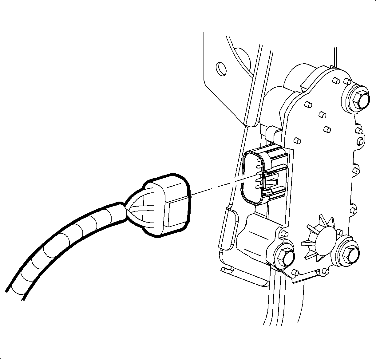
- Disconnect the electrical connector from the APP sensor.
- Loosen the brake booster mounting nuts.
- Remove the retaining clip (4) and washer (3) from the brake pedal.
- Release the brake booster pushrod (2) from the brake pedal.
- Remove the brake booster mounting nuts.
- Remove the brake pedal bracket-to-steering column bracket bolt (1).
- Lower the brake pedal assembly to improve access for switch removal.
- Remove the stop lamp switch from the pedal bracket. Refer to Stop Lamp Switch Replacement in Lighting Systems.
- Remove the cruise control release switch, if equipped, from the pedal bracket. Refer to Cruise Control Release Switch Replacement in Cruise Control.
- Remove the brake pedal assembly, with the accelerator pedal assembly from the vehicle.
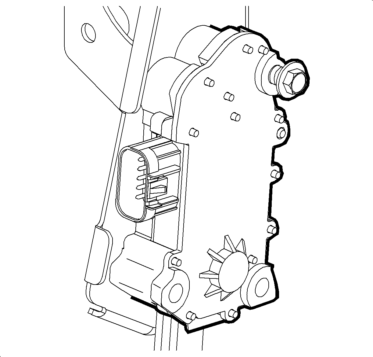
- Remove the accelerator pedal mounting bolts and remove the pedal assembly.


Installation Procedure
- Position the accelerator pedal assembly to the brake pedal bracket.
- Install the accelerator pedal and sensor assembly mounting bolts.
- Install the brake pedal assembly, with the accelerator pedal assembly to the vehicle.
- Install the cruise control release switch, if equipped, to the pedal bracket. Refer to Cruise Control Release Switch Replacement in Cruise Control.
- Install the stop lamp switch to the pedal bracket. Refer to Stop Lamp Switch Replacement in Lighting Systems.
- Move the brake pedal assembly to the installed position.
- Install the brake pedal bracket-to-steering column bracket bolt (1).
- Loosely install the brake booster mounting nuts.
- Apply a thin coating of lithium grease to the pushrod pin on the brake pedal.
- Connect the brake booster pushrod (2) to the brake pedal.
- Install the washer (3) and retaining clip (4) to the brake pedal.
- Tighten the vacuum brake booster mounting nuts.
- Adjust the stop lamp switch. Refer to Stop Lamp Switch Adjustment in Lighting Systems.
- Adjust the cruise control release switch, if equipped. Refer to Cruise Release Switch Adjustment in Cruise Control.
- Connect the electrical connector to the APP sensor.
- Secure the APP sensor jumper harness to the brake pedal bracket.
- Secure the EPS wiring harness to the pedal bracket.

Notice: Refer to Fastener Notice in the Preface section.
Tighten
Tighten the bolts to 9 N·m (80 lb in).


Tighten
Tighten the bolt to 25 N·m (18 lb ft).
Tighten
Tighten the nuts to 25 N·m (18 lb ft).

