For 1990-2009 cars only

Caution: Refer to Brake Fluid Irritant Caution in the Preface section.
Notice: Refer to Brake Fluid Effects on Paint and Electrical Components Notice in the Preface section.
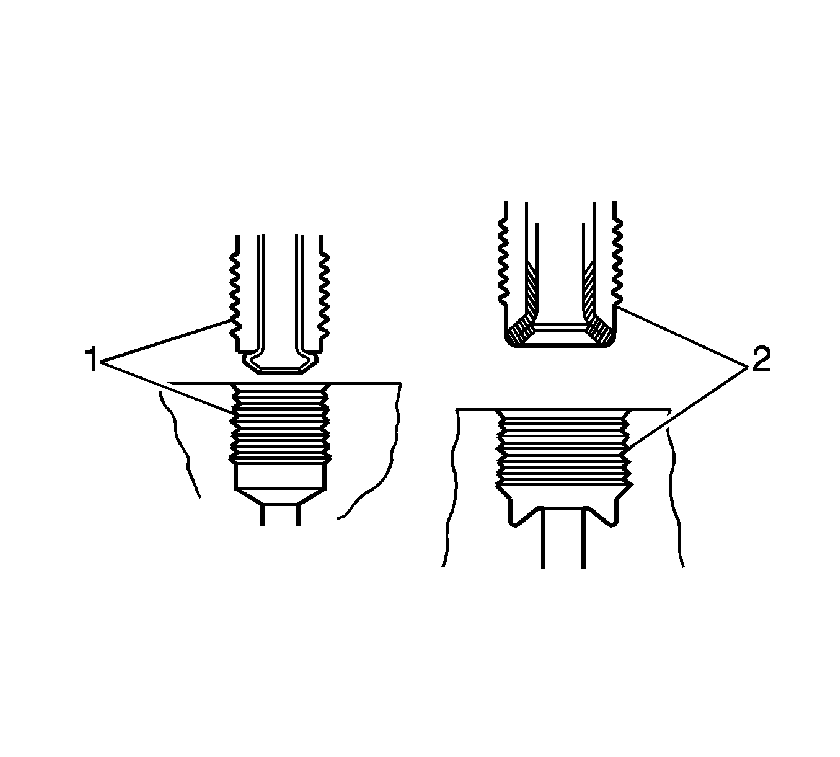
Notice: There is a first design and second design of brake pipe flare for the hydraulic
brake pipes and system components used on this vehicle. Do NOT mis-match flare types.
If the flare types are mis-matched, damage to the pipes and/or components, and/or
a brake fluid leak may occur.
• First design, ISO flare (1) • Second design, double inverted flare (2)
Removal Procedure
- Raise and support the vehicle. Refer to Lifting and Jacking the Vehicle in General Information.
- Remove the tire and wheel assembly. Refer to Tire and Wheel Removal and Installation in Tires and Wheels.
- Clean all dirt and foreign material from the brake hose ends and brake pipe fittings.
- Using a backup wrench on the hose fitting, disconnect the brake pipe fittings from the brake hose. Cap or plug the brake pipe fitting ends and the brake hose ends to prevent fluid loss and contamination.
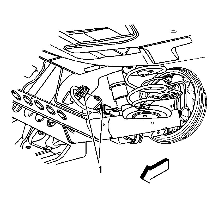
- Remove the brake hose retaining clips (1) from the hose mounting brackets.
- Remove the hose from the mounting brackets.

Installation Procedure
- Install the brake hose to the brake hose mounting brackets. Align the hose fittings with the notch in the brackets.
- Install the hose retaining clips (1) onto the hose fittings at the hose brackets.
- Using a backup wrench on the hose fitting, connect the brake pipe fittings at the rear brake hose.
- Install the tire and wheel assembly. Refer to Tire and Wheel Removal and Installation in Tires and Wheels.
- Ensure that the hose does not make contact with any part of the suspension. If the hose makes contact, remove the hose and correct the condition.
- Bleed the hydraulic brake system. Refer to Hydraulic Brake System Bleeding .
- Lower the vehicle.

Notice: Refer to Fastener Notice in the Preface section.
Tighten
Tighten the fittings, first or second design to 19 N·m (14 lb ft).
