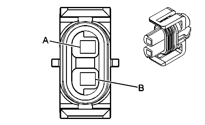
| Table 1: | A/C Compressor Clutch |
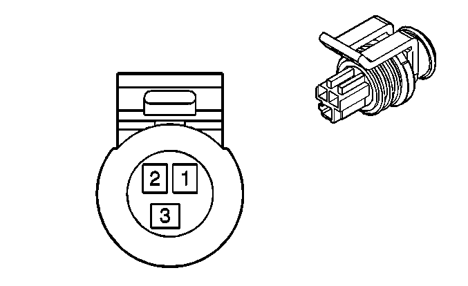
| Table 2: | A/C Refrigerant Pressure Sensor |
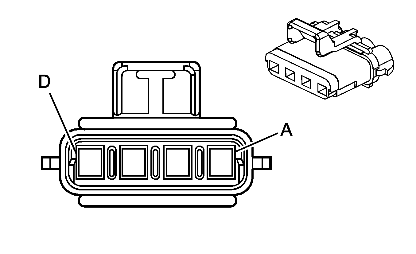
| Table 3: | Blower Motor Resistor Assembly |
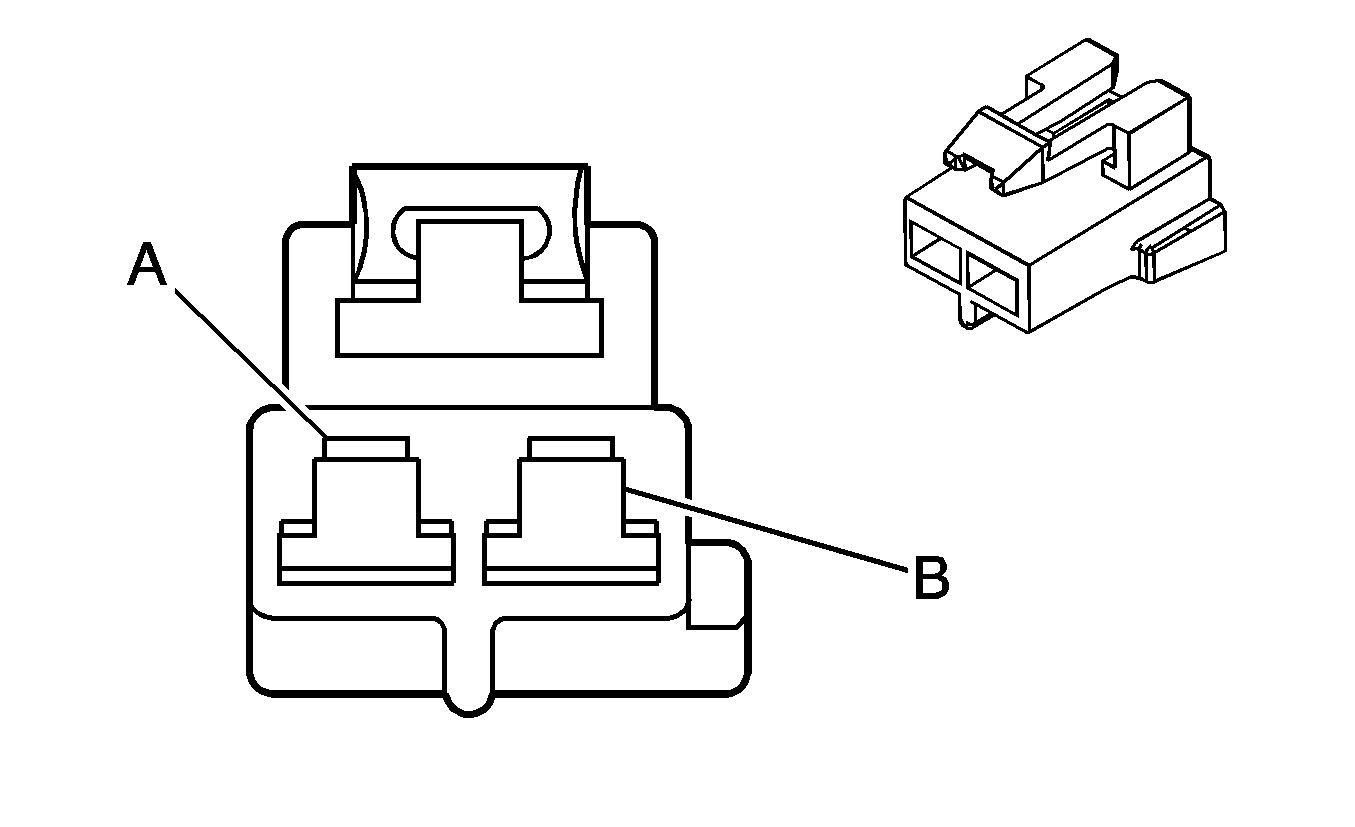
| Table 4: | Blower Motor |
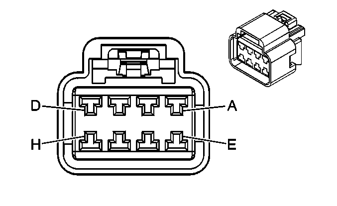
| Table 5: | HVAC Control Assembly C1 |
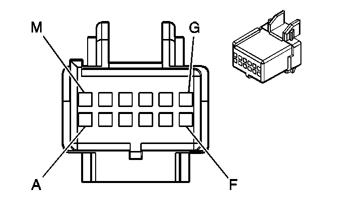
| Table 6: | HVAC Control Assembly C2 |
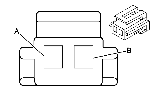
| Table 7: | Recirculation Actuator |
| |||||||
|---|---|---|---|---|---|---|---|
Connector Part Information |
| ||||||
Pin | Wire Color | Circuit No. | Function | ||||
A | D-GN | 59 | A/C Compressor Clutch Supply Voltage | ||||
B | BK | 150 | Ground | ||||
| |||||||
|---|---|---|---|---|---|---|---|
Connector Part Information |
| ||||||
Pin | Wire Color | Circuit No. | Function | ||||
1 | BK | 2751 | Low Reference | ||||
2 | GY | 2700 | 5V Reference | ||||
3 | RD/BK | 380 | A/C Refrigerant Pressure Sensor Signal | ||||
| |||||||
|---|---|---|---|---|---|---|---|
Connector Part Information |
| ||||||
Pin | Wire Color | Circuit No. | Function | ||||
A | TN | 63 | Blower Motor Medium 1 Control | ||||
B | L- BU | 72 | Blower Motor Medium 1 Control | ||||
C | OR | 52 | Blower Motor Supply Voltage | ||||
D | YE | 60 | Low Blower Motor Control | ||||
| |||||||
|---|---|---|---|---|---|---|---|
Connector Part Information |
| ||||||
Pin | Wire Color | Circuit No. | Function | ||||
A | BK | 550 | Ground | ||||
B | OR | 52 | Blower Motor Supply Voltage | ||||
| |||||||
|---|---|---|---|---|---|---|---|
Connector Part Information |
| ||||||
Pin | Wire Color | Circuit No. | Function | ||||
A | OR | 52 | High Blower Motor Control | ||||
B | L- BU | 72 | Medium 2 Blower Motor Control | ||||
C | TN | 63 | Blower Motor Medium 1 Control | ||||
D | YE | 60 | Blower Motor Low Control | ||||
E-F | -- | -- | Not Used | ||||
G | BN | 41 | Ignition 3 Voltage | ||||
H | -- | -- | Not Used | ||||
| |||||||
|---|---|---|---|---|---|---|---|
Connector Part Information |
| ||||||
Pin | Wire Color | Circuit No. | Function | ||||
A | -- | -- | Not Used | ||||
B | BN | 141 | Ignition 3 Voltage | ||||
C | L-GN | 66 | A/C Request Signal | ||||
D | -- | -- | Not Used | ||||
E | L-GN/BK | 1647 | Recirculation Door Control B | ||||
F | PK/WH | 1648 | Recirculation Door Control A | ||||
G | WH | 193 | Rear Defog Relay Control | ||||
H | -- | -- | Not Used | ||||
J | L- BU | 292 | Rear Defog Switch Signal | ||||
K | BK | 550 | Ground | ||||
L | GY | 8 | Instrument Panel Lamp Supply Voltage | ||||
M | -- | -- | Not Used | ||||
| |||||||
|---|---|---|---|---|---|---|---|
Connector Part Information |
| ||||||
Pin | Wire Color | Circuit No. | Function | ||||
A | PK/WH | 1648 | Recirculation Door Control A | ||||
B | L-GN/BK | 1647 | Recirculation Door Control B | ||||
